

1⁄35Sd. Kfz. 231 Early Type
3
Comments
The Build
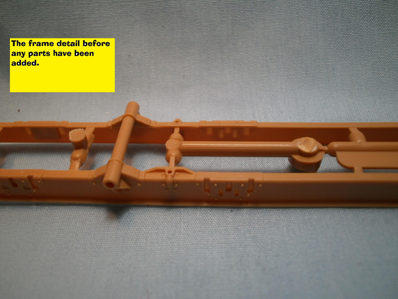
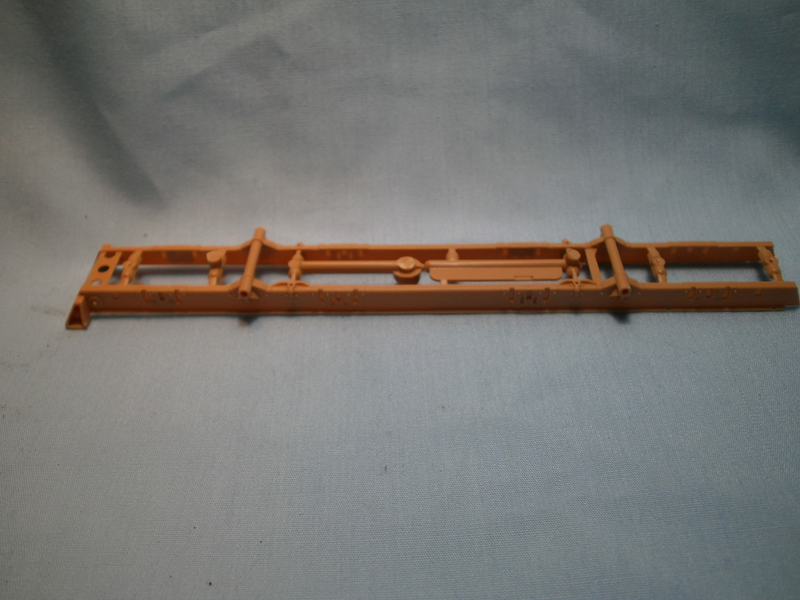
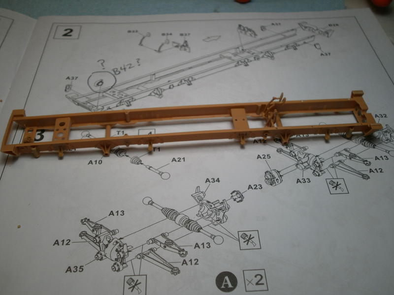
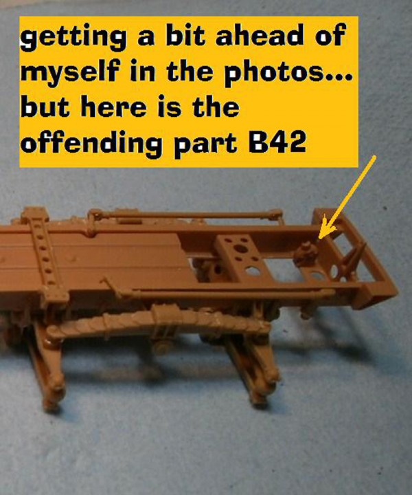
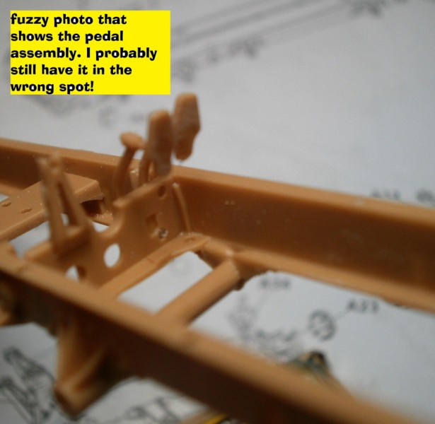
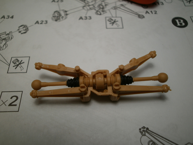
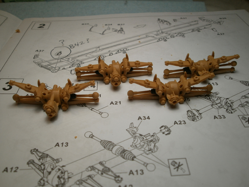
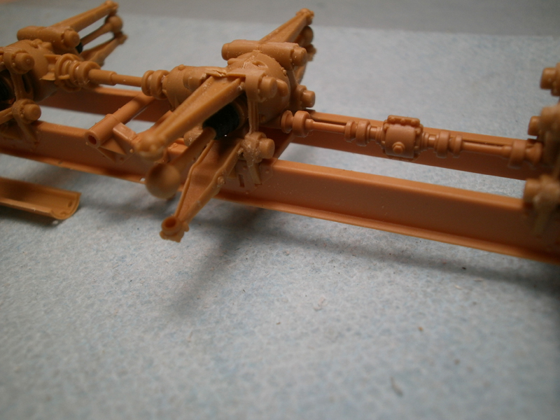
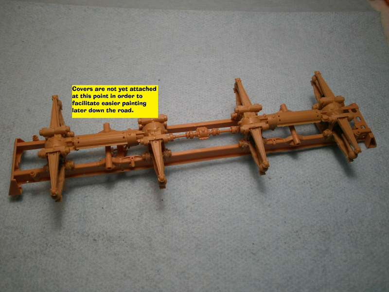
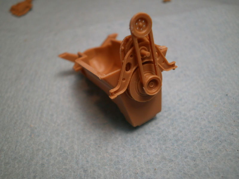
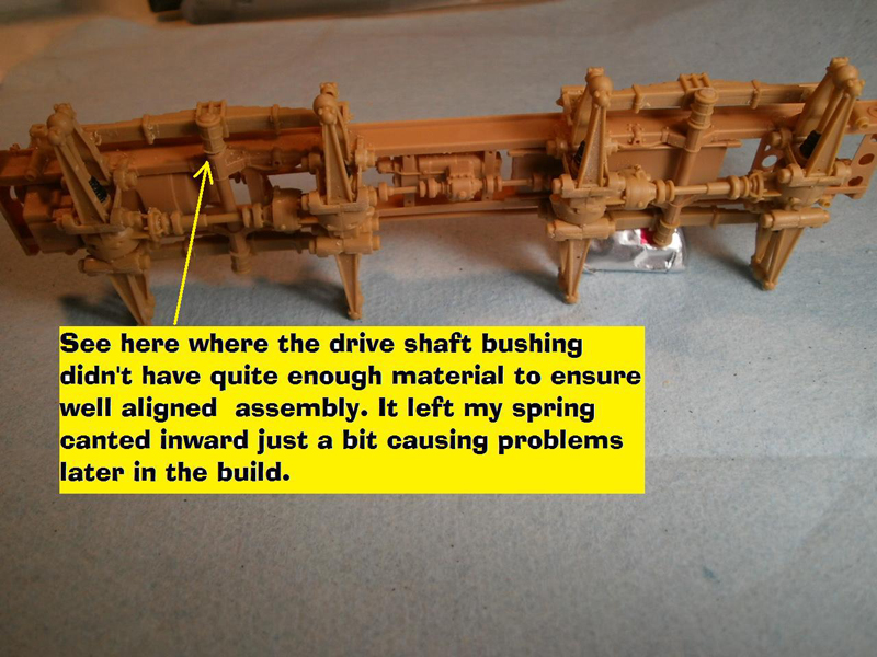
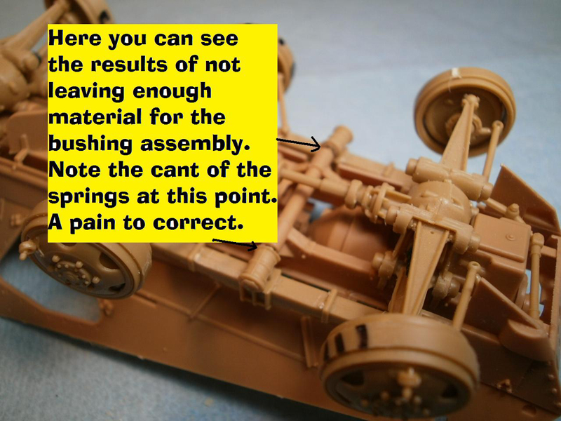
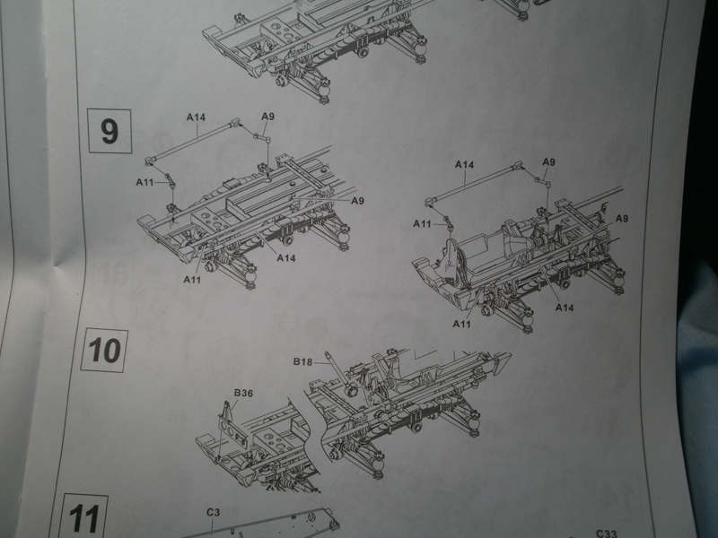
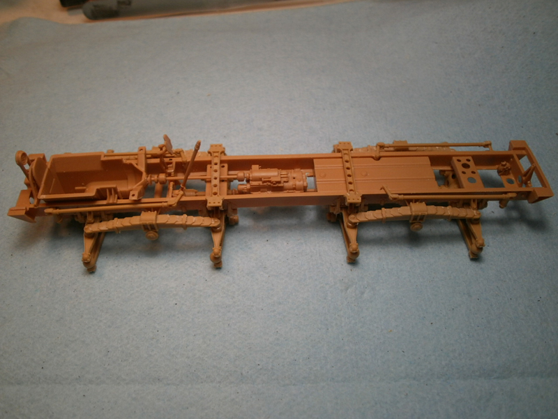
Step one is a quickie, adding the bump stops and a couple of separate frame cross members. The frame comes in a separate package in order to keep it safe? I dont know that I have ever run into any problem with poorly packaged frames before but, hey, it was still pretty cool, its own little plastic tub! It took me about 15 minutes to finish this step. A couple of photos off to the side show a bit, dont really show off the molded in detail well but it is nicely rendered and of course the frame makes everything nice and square which will help in subsequent steps. Step two ads a bit more of the frame as well as some of the drivers pedals to the build. It also introduces the first issue with the kit. Part B42, the steering gear, is unmarked but important; it is the piece that later on will accept the steering column for the front driving station so you dont want to forget it. The other issue in this step is the fuzzy location of the housing for the foot pedals as well as the aforementioned part B42. Best advice; go slow and easy here. Step three: Here we have the beginnings of the suspension and the drive train. This will sound like a broken record throughout the review but let me say it anyway; absolutely superb engineering throughout all these pieces and parts. This was a lot of fun to put together because of the excellent fit, clean-up was slowed a bit due to all the nodes (slide molding?) but a pass or two with a nail file and everything was good to go. The photos off to the side show the axles set into the differentials before they are trapped and secured, and the set of four completed assemblies looking a bit like a flight of four x-wing fighters! The only thing I would warn you about during this step is to advise you to clip off and put the driver knows poles off to the side, where they reside on the sprue is smack in the middle of a lot of the parts for this step and they are more than just a bit fragile and you wouldnt want to break one at this early stage. (You probably wouldnt actually want to break them at any point!) Step four: Pretty easy here, you will be attaching the suspension systems and assemblies you just finished onto the frame as well as adding the drive shafts. I kept the shaft covers (A24) off until the end for easier painting. A few photos of to the side give you an idea of what it all looks like at this point. Step five: Faux engine .why? Okay, building was easy enough, as was the gas tank and the drive shaft from the engine to the central differential. However, if AFV Club was going to give us a partial engine, why not include the radiators and cooling system which creates something of a firewall between the engine and the rear facing driver? As it is you get a half engine which nicely fills the space from the bottom up but not from the inside of the crew compartment. Granted it is pretty dark inside even with hatches open but it may be something you want to correct. I left it as is in my build going for the traditional out of box style for the purposes of showing the kit components only. Step six and seven: Some more pieces attached to the frame, supports and cross supports and one piece that I assumed was part of the steering system for the two drivers. All pretty easy stuff, very well done. Step eight: Be careful, a small trap here for the unwary (unaware, my normal state of mind!). Here is where you add the leaf springs to the frame/chassis assembly. Part A17 is the bushing and bolt assembly for the leaf springs and is attached to the sprue at the end of the bolt. Be careful not to cut it off to close to the bushing or you will end up with too little to insert into the housing leaving your springs out of square. Also, make certain that the leaf springs are nice and straight at this point; the lower half of the hull fit tightly behind the springs and if you are canted to the inside just a bit it will make later assembly a real chore. Now I know all this because of a very careful study of the instructions, NOT because I wasnt as careful as I should have been! (Thats my story and Im sticking with it!) Step nine: Pretty simple, here is where you add the tie rods for the double steering system. Just a few parts from the A sprue only, three per assembly, for the four steering units, a tiny bit of sanding to clean-up the parts and you are good to go. Step ten: Another very easy step, two parts only, the rear steering column and the front bracket that holds the drivers pedals and gas pedal linkage. A really odd combination of parts for a single step! One thing to be careful of is the location for the rear steering column, it is a bit unclear. It is marked but the drawing gets a bit busy and its an easy one to miss the exact location of.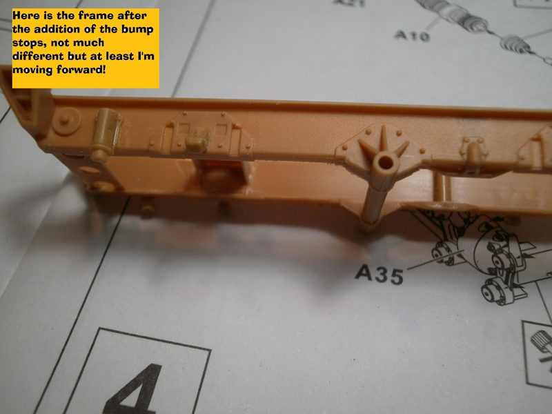
About the Author


FROM: CALIFORNIA, UNITED STATES
I have been modeling for about 30 years now. Once upon a time in another century I owned my own hobby shop; way more work than it was worth. I tip my opti-visor to those who make a real living at it. Mainly build armor these days but I keep working at figures, planes and the occasional ship.
Comments


Yes, 1:35 scale...apologies, I had a broken link to the video review...all fixed now
MAY 19, 2012 - 02:50 AM
Copyright ©2021 by Rick Cooper. Images and/or videos also by copyright holder unless otherwise noted. The views and opinions expressed herein are solely the views and opinions of the authors and/or contributors to this Web site and do not necessarily represent the views and/or opinions of Armorama, KitMaker Network, or Silver Star Enterrpises. All rights reserved. Originally published on: 2012-05-05 00:00:00. Unique Reads: 14238

WEB HOSTING BY


Copyright ©2021 Armorama and Kitmaker Network, a subsidiary of Silver Star Enterprises
All Rights Reserved. Please read our Conditions of Use and Privacy Policy.
All Rights Reserved. Please read our Conditions of Use and Privacy Policy.