

1⁄35Sd. Kfz. 231 Early Type
3
Comments
steps 11 27
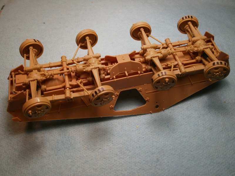
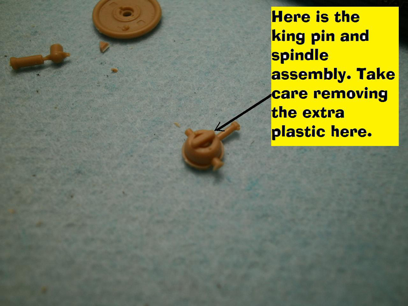
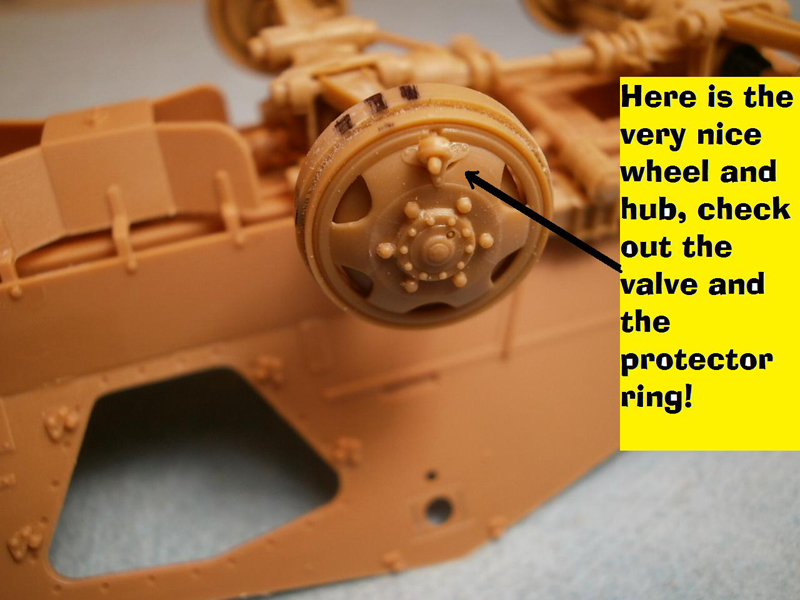
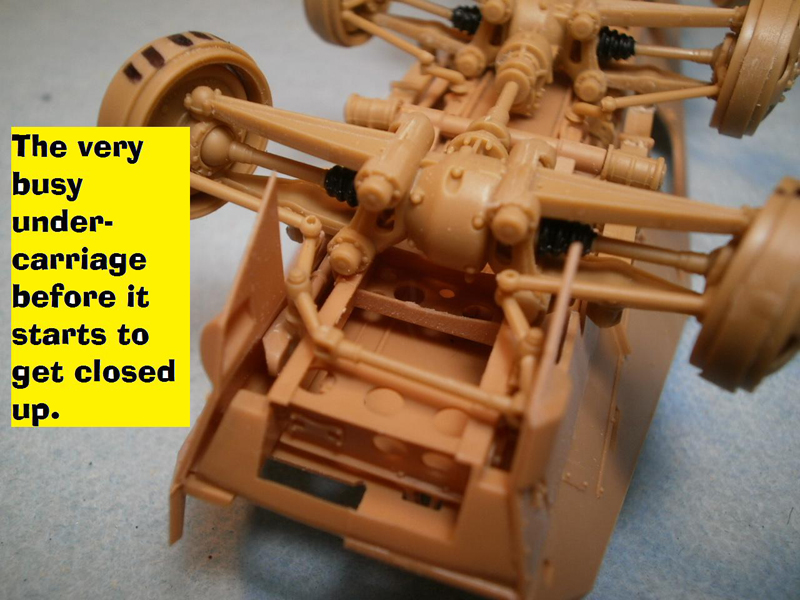
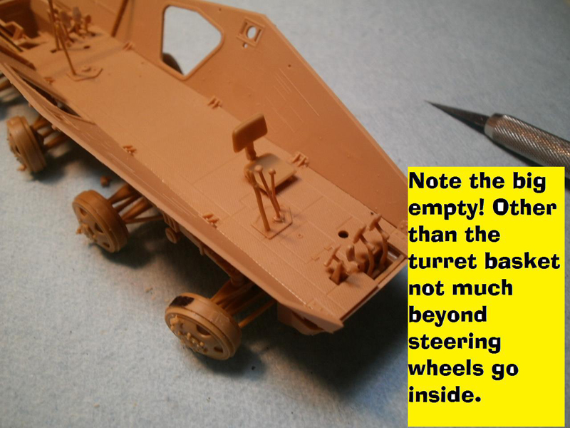
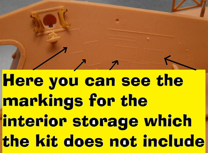
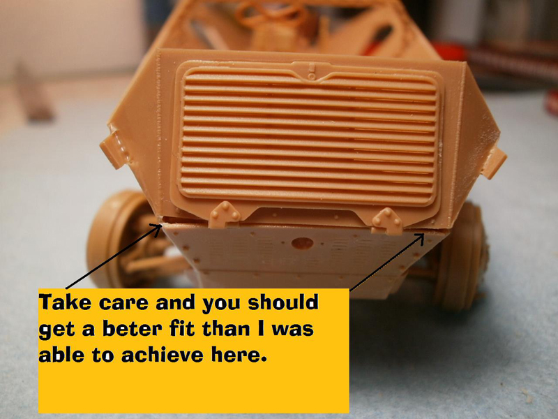
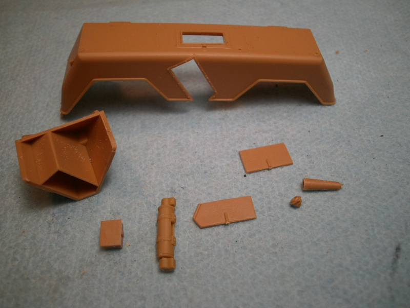
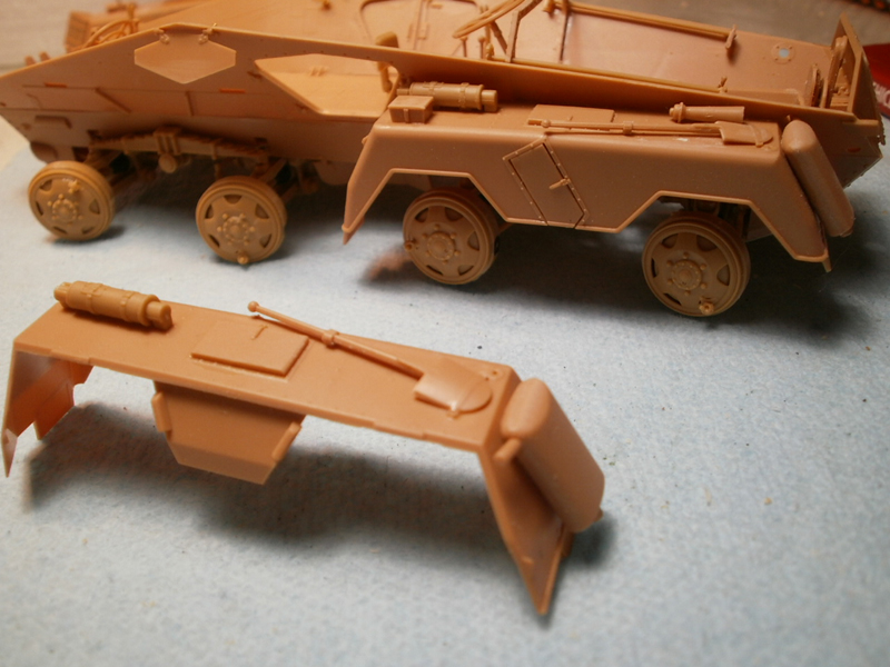
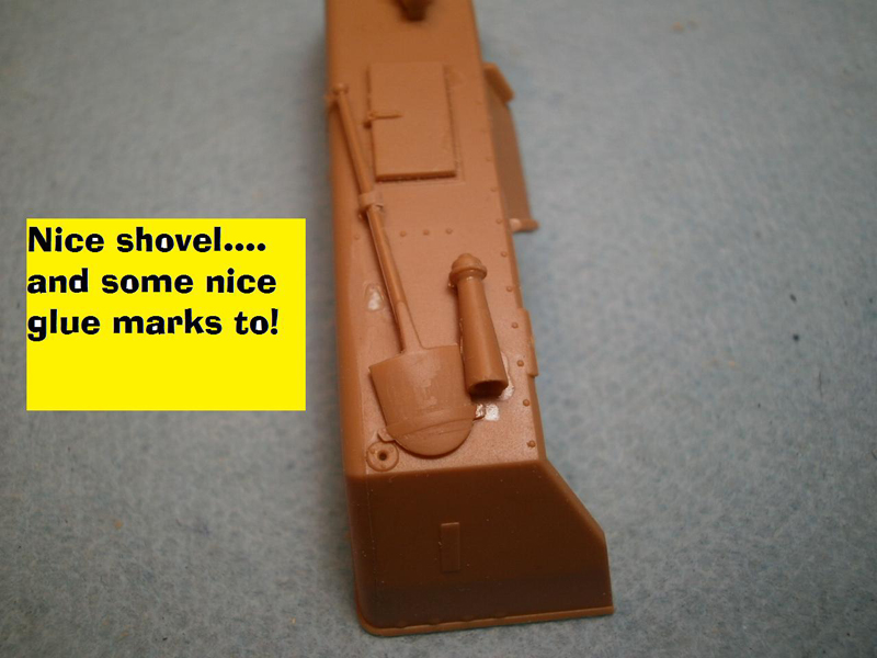
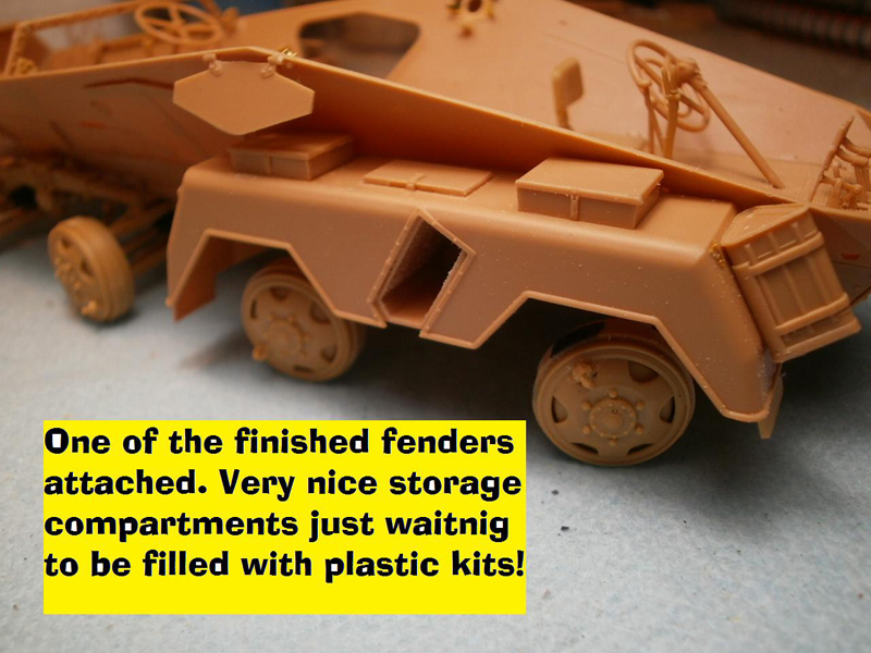
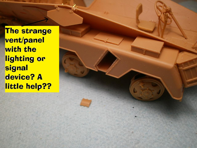
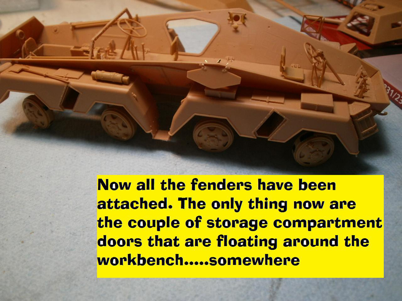
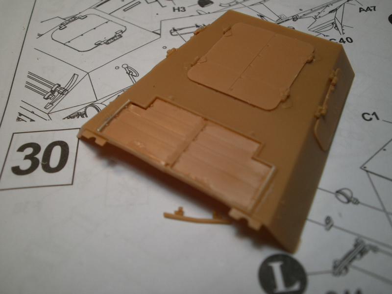
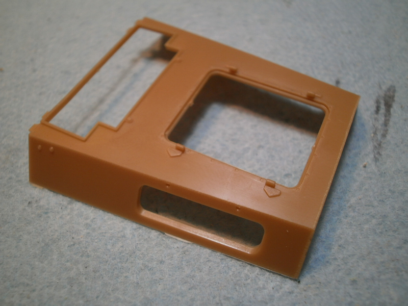
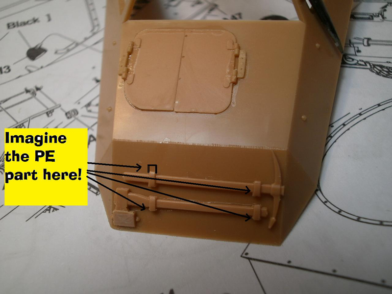
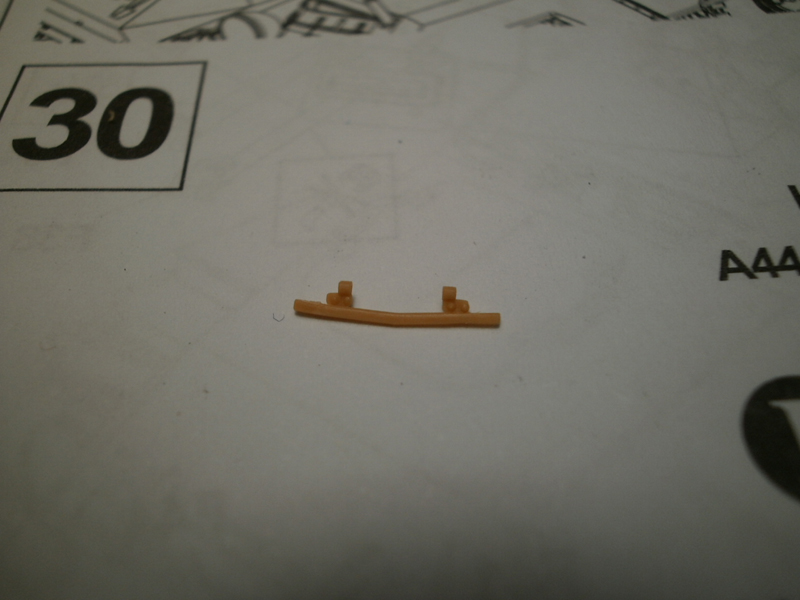
Step eleven and twelve: Now the fun starts, well if you are like me anyhow where the building of the suspension and undercarriage is simply a chore to be endured before you get to the hull and turret. On the other hand, if you are a big chassis fan, well your fun is almost over! Step eleven is our introduction to the construction of the hull and interior. Only a few things to do but vitally important to keep it all aligned. You will add the floor, the lower hull sides along with the bolted stringer that keeps the proper angle of the sides as well as the two plates that house the gear shifts and hand brakes. AFV Club has done a good job of providing a fairly positive set of mating surfaces where the critical hull floor and sides meet, but like anything test fit once, twice, and even three times before applying any glue. I would recommend using some kind of liquid cement so that you have a bit of working time with the interior stringer/truss piece. When you have it properly aligned step twelve is where you attach the lower hull to the framework. One thing to note throughout the entire undercarriage process is the great level of detail that AFV Club has put into the underside of the kit. Step thirteen: Wheels, hubs, and tires. Five parts for each assembly not including the valve stem (thank you AFV Club for including this!) and the protector ring (at least I think that is what it is, part A19, if anyone knows different please share). I left my tires of until the end to ease the painting process, dont know that I would do that a second time, it was a bit tricky to get them back on without breaking anything. Step fourteen: A tricky step here. This is where the lower hull extension is added to both sides. It is a long thin piece (B19 and B6) that is tricky to get in the right spot. Be careful the instructions can be a bit fuzzy as step 15 shows the part in a slightly different location, step 15 places this piece on the outside of the leaf springs, but it should just slip in behind. Being a long piece provides a bit of a challenge getting everything lined up so take some extra care here. This step also adds the rather large and chunky protective cover for the central power takeoff. This should slip right into place and looks great after installation. Step fifteen: This is a pretty simple step, add the steering cross ties and the front and rear skid plates/lower hull and you are on your way to step 16. Step sixteen and seventeen: This step adds the drivers pedals, seats, shifters, and hand brakes. This is where you realize just how empty the interior of this big guy is. You will note markings on the side walls for extra equipment such as first aid boxes, spares, map cases, spare ammo, flashlights and other signals, but the kit provides none of these. Perhaps AFV Club will do an add-on kit or is working with a resin company that will come out with a more complete interior. I left mine empty as I wanted an out of box experience for the review, but I may go back in and add them. If you want to add them this is a good spot to add some extra interior detail. Also, the steering column, B22, for the front driver is added here, it just gives you the old arrow here through this hole trick without telling what you connect to inside the hole. This is where the unmarked steering gear part B42, comes into play, the steering column should fit right into this. Step eighteen: Adds the engine grill and the grill housing. I could never get a good fit as the photo attests to and eventually just gave up and said good enough, may you have better luck. Step nineteen: This is one of those spots where a bit of explanation would have helped. You are given a choice between two different sets of parts, C34 and 35 or C36 and 37. The problem is that it is hard to tell what the choices will mean later on. The parts are for the engine side vent cooling louvers, the first set, C34 and 35 will give you opened side vents, the second group will leave you with closed vents. The issue comes later when the instructions simply tell you to attach the side louver in the closed position without offering the option. You can easily display them open but the instructions arent clear at all. Also, remember you have no real engine, so open only makes sense if you fill the space with something. You also have the rear drivers dashboard to install at this point. I opted to install later so that the painting went a bit easier. It was at this point that I started the painting of the interior. One more small issue with this step, parts A40 and A48 are the control mechanism for the engine side vent louvers, the instructions only show parts and installation for the right side yet show the installed parts on both sides. Fortunately the part numbers are the same for the left and right, just dont forget to add them even if not called out. Step twenty: This is where you add the large side doors as well as a few parts for what I think is some type of signaling or station keeping system. It consists of some outside vents or panels that are opened and closed by a push bar. Inside you have a couple of photo-etch pockets to add that will accept a small piece that resembles a pocket door; it slides in and out of the photo-etch pocket. Later you will add the light arrangement for the whole shooting match; again, if someone has a better answer as to what this whole assembly is for please share with the rest of us. Steps twenty-one through twenty-five: The building and attachment of the four large fender assemblies. These steps are all very straight forward with great detail throughout the whole process. Each of the small storage compartments opens, and best of all, none of them open into an empty hole. Each one opens into a provided compartment that will lend itself to some great super detailing in the hands of a master. I left some of the pieces off for ease of handling and painting, namely the mufflers and driver knows poles as well as the PE muffler guards. You will need to open the locating holes from the underside of the fender for the most of the on board equipment, nice if you are planning on swapping out with aftermarket materials or PE supplements. You do have a couple of nice shovels to add here that dont have full hold down clasps but the PE sheet does have the small flip releases that can be added. They are not noted or shown on the instructions so be aware of their existence if you want to add a bit extra to your build. Step twenty-six: add the front and rear headlights and the license plates. Really, thats it. Step twenty-seven: The engine deck, cooling louvers, those aforementioned side cooling vents, and the access panels for the engine. Pretty straightforward, but remember if you used the hinge parts to hold open the side vents you dont want to glue them down inadvertently now. A nice detail is the separate hinge parts for the side vents, somewhat fiddly but they look nice nonetheless. Also, this is where you add the front drivers dashboard to the underside of the upper hull before attaching it in the next step.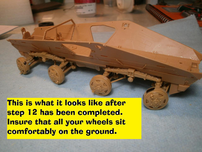
About the Author


FROM: CALIFORNIA, UNITED STATES
I have been modeling for about 30 years now. Once upon a time in another century I owned my own hobby shop; way more work than it was worth. I tip my opti-visor to those who make a real living at it. Mainly build armor these days but I keep working at figures, planes and the occasional ship.
Comments


Yes, 1:35 scale...apologies, I had a broken link to the video review...all fixed now
MAY 19, 2012 - 02:50 AM
Copyright ©2021 by Rick Cooper. Images and/or videos also by copyright holder unless otherwise noted. The views and opinions expressed herein are solely the views and opinions of the authors and/or contributors to this Web site and do not necessarily represent the views and/or opinions of Armorama, KitMaker Network, or Silver Star Enterrpises. All rights reserved. Originally published on: 2012-05-05 00:00:00. Unique Reads: 14238

WEB HOSTING BY


Copyright ©2021 Armorama and Kitmaker Network, a subsidiary of Silver Star Enterprises
All Rights Reserved. Please read our Conditions of Use and Privacy Policy.
All Rights Reserved. Please read our Conditions of Use and Privacy Policy.