

1⁄35M1 ABV The Build
4
Comments
Next was the turret rear.
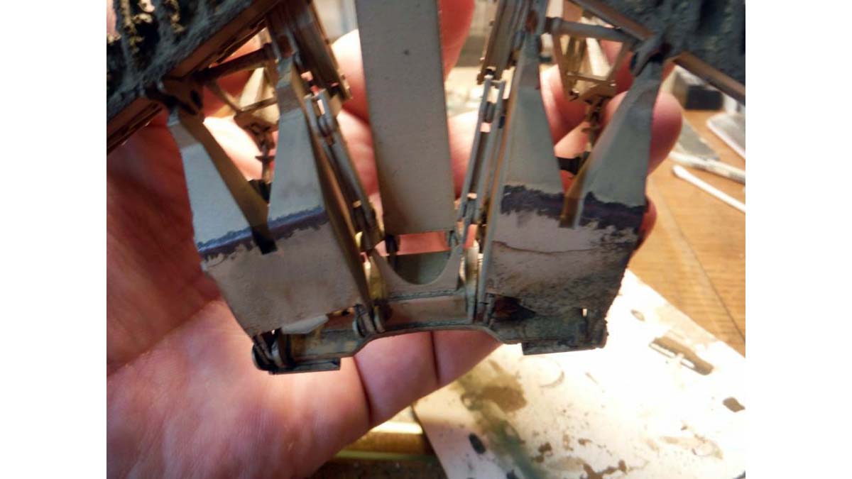
I started with filling the dimple found on the inside of the rear swing doors. On the real vehicle, part L6 is attached to the door and not to the MICLIC frame. When adding the parts to the doors in step 4G, just add the part instead of adding it step 4H. I added the missing hinges to the smoke grenade boxes. These are very prominent on the real vehicle. Speaking of smoke grenade boxes? Again, if you want to make an Army version, leave off parts N81 and N82 and attach part C18 instead.
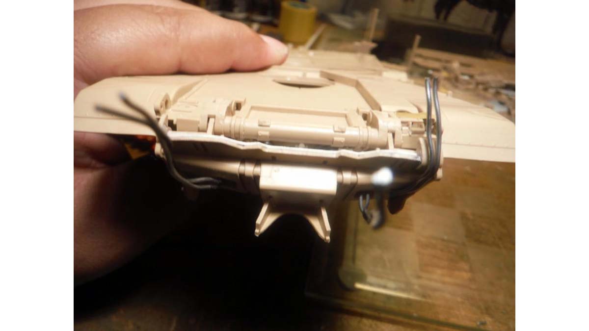
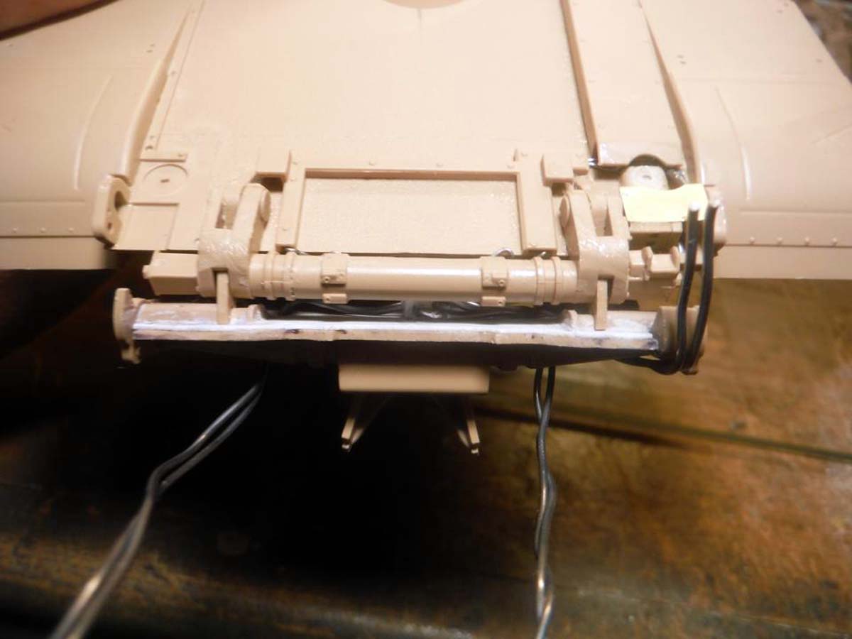
After the swing doors were done, I went on and built the rear turret frame and attached it instead of doing it in Step 7. But before attaching, I made some corrections, filled punch marks and added cables. Holes were drilled out for cables that will be routed through the frame. DUKE Antenna cables and the GPS antenna and cable were also added at this time. Other miscellaneous cables that can be seen on the real thing were also added. At the point of the build, I skipped the MICLIC's and Lane Marking System and went to the hull and plow. Since the hulls are basically the same in all four kits, I'll just cover the ABV stuff.
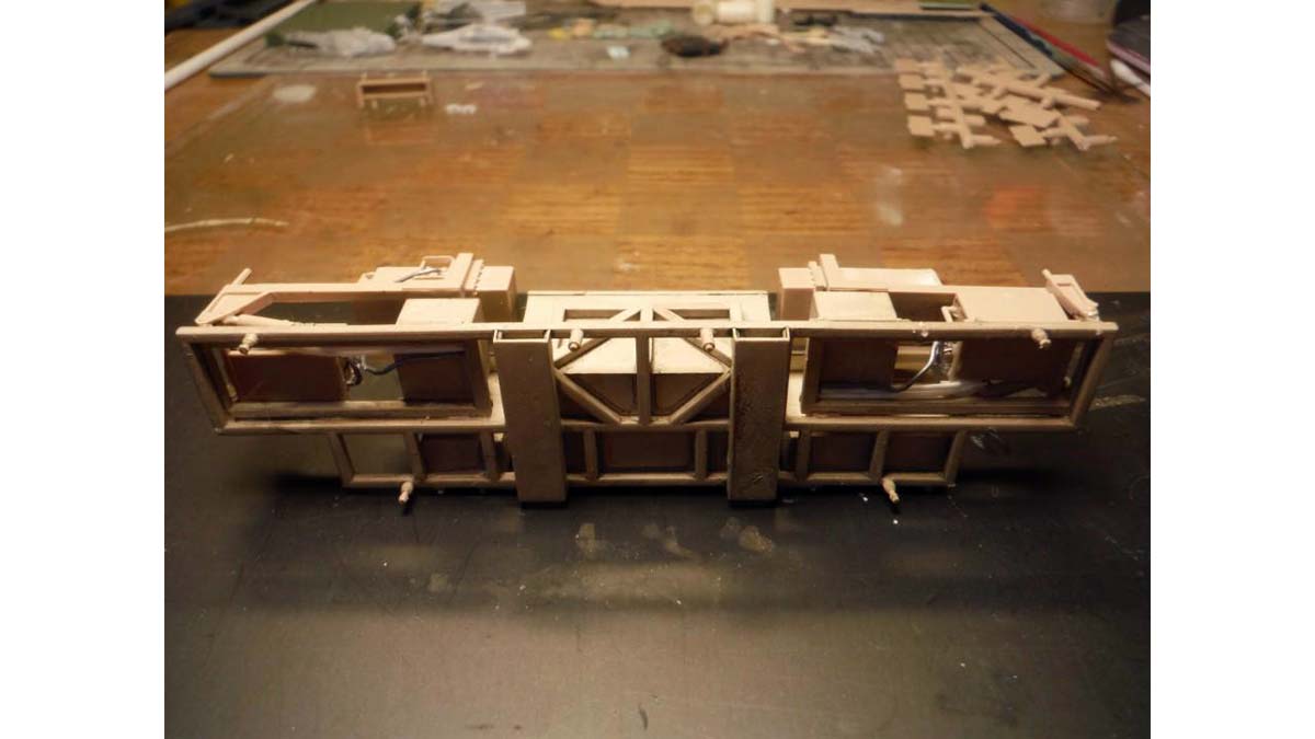
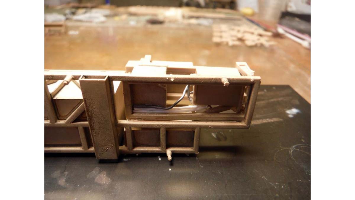
NOTE: Remember to fill and sand flush the fuel plate to the hull on the left rear side
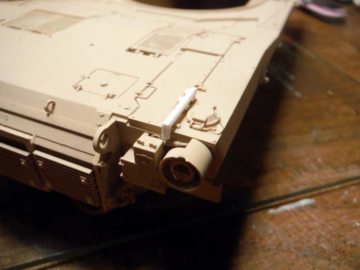
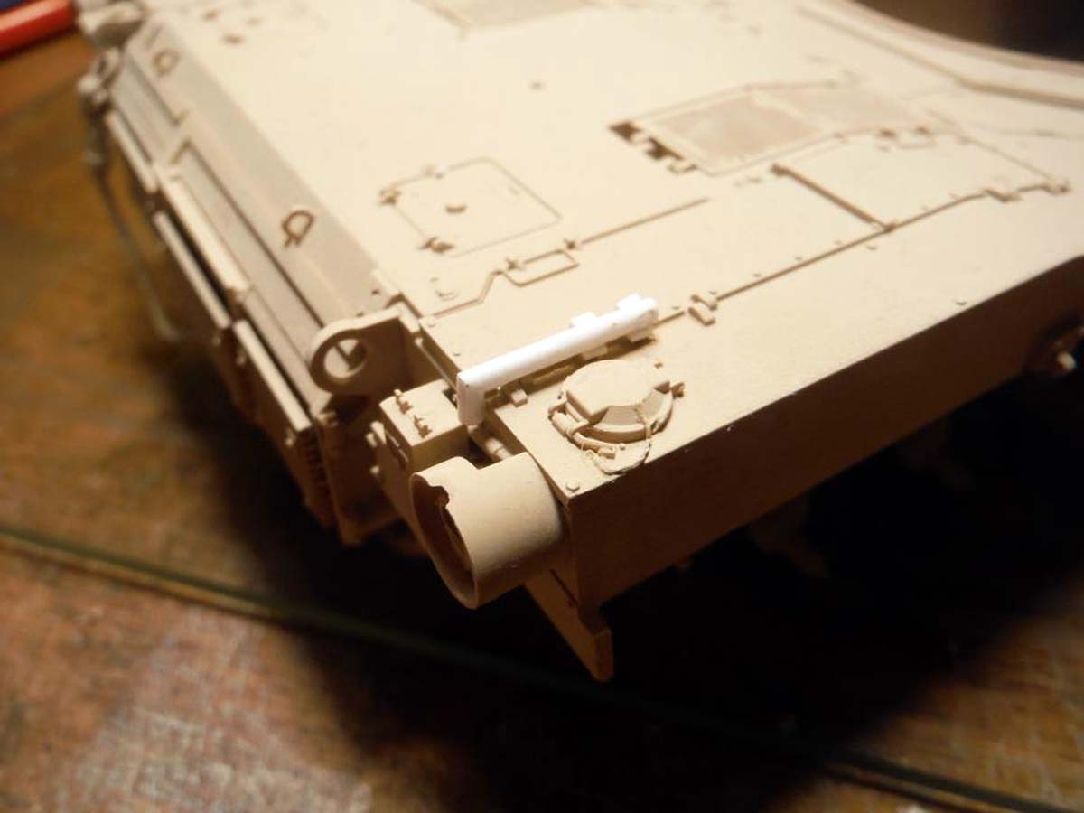
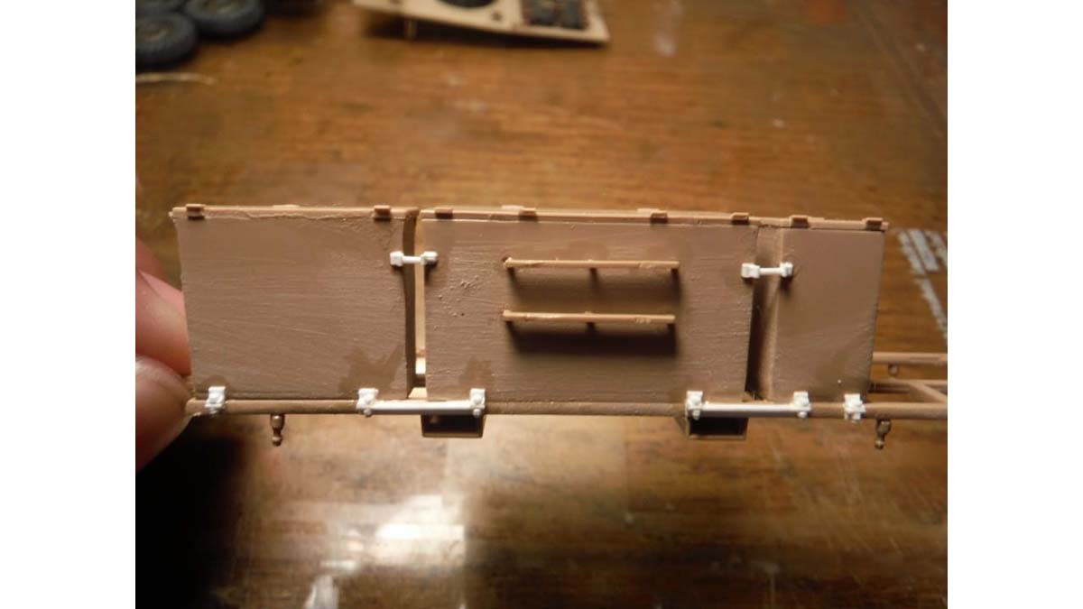
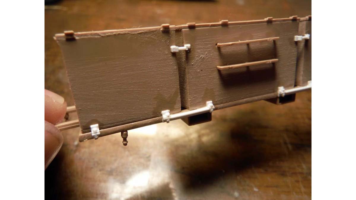
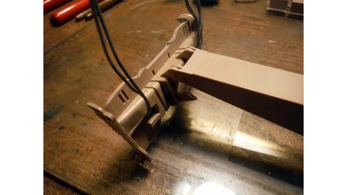
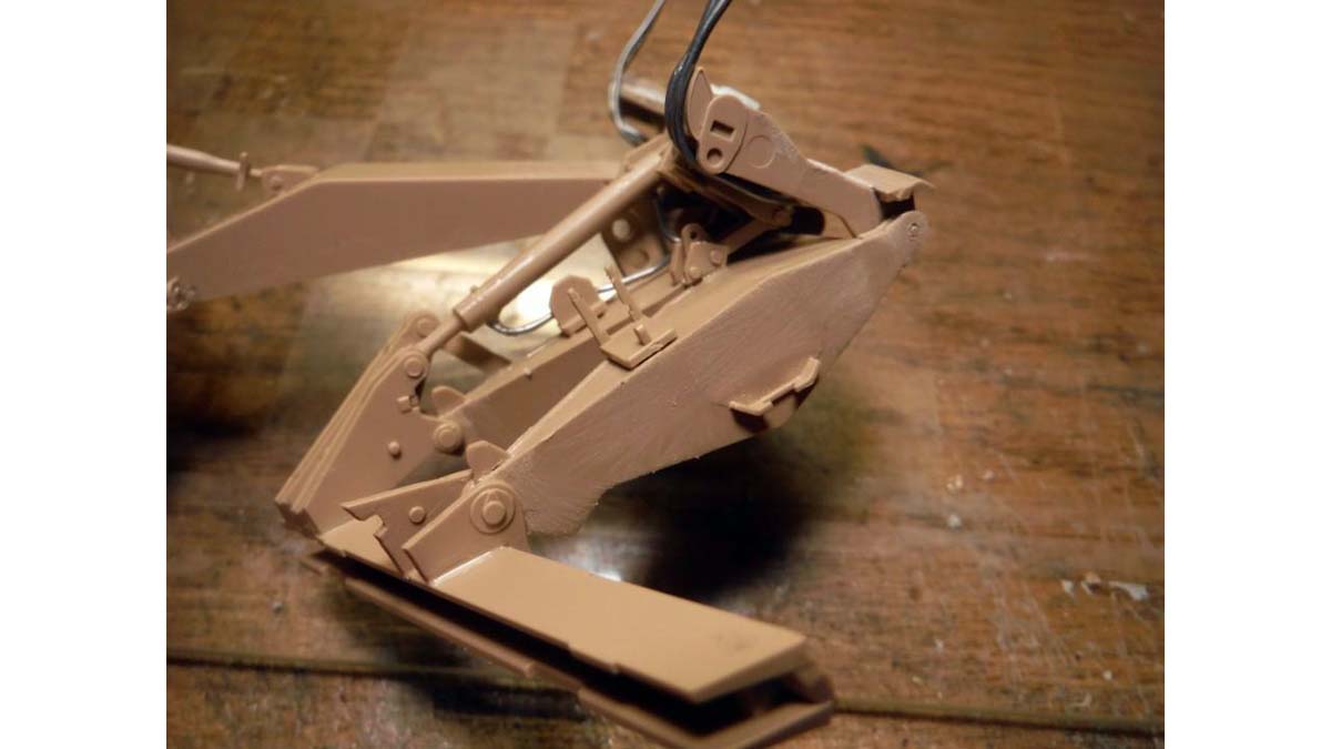
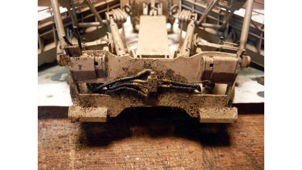
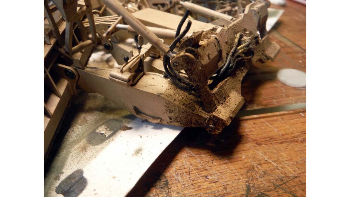
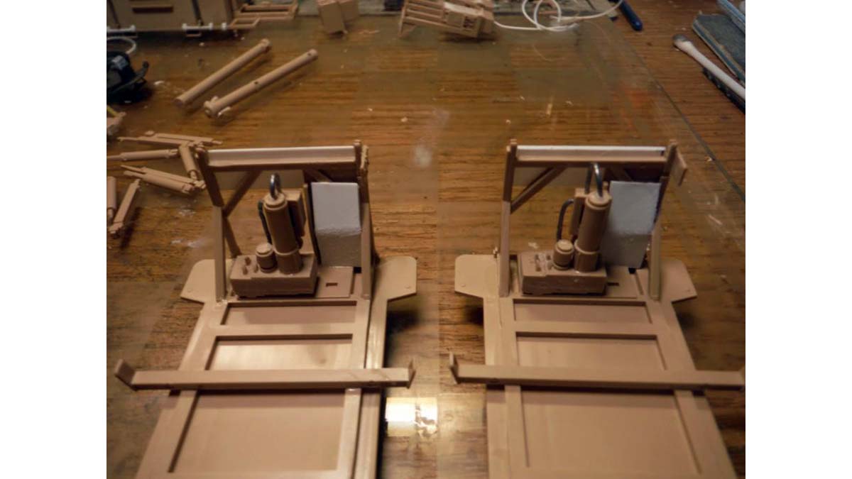
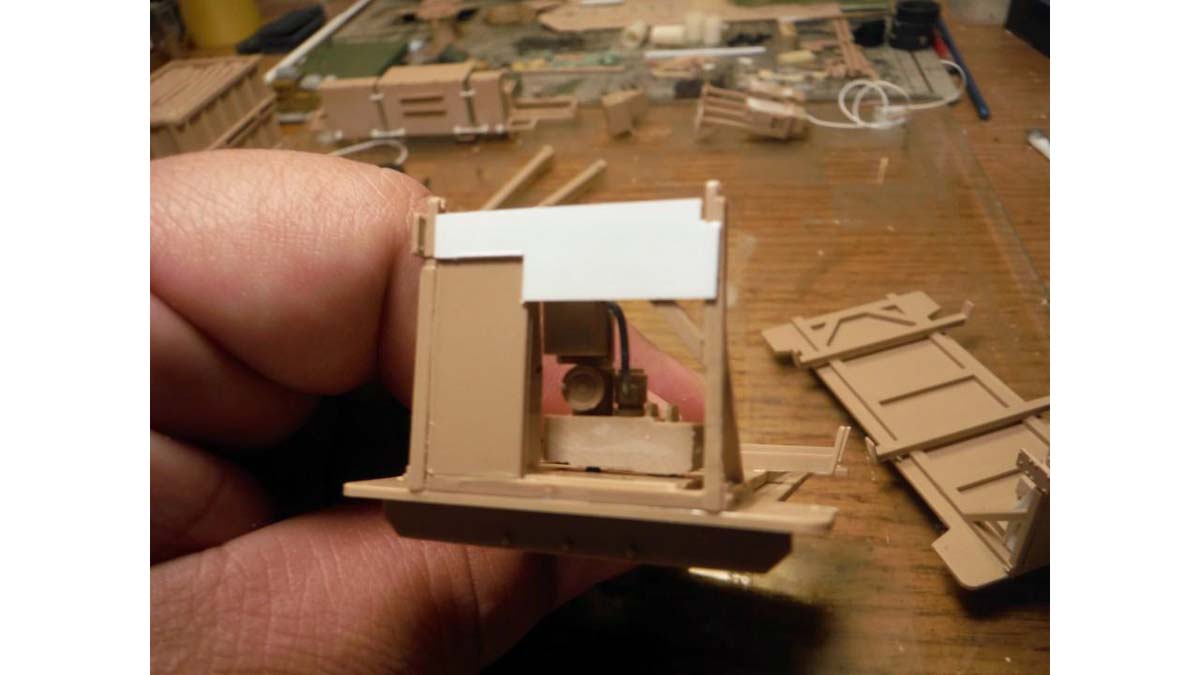
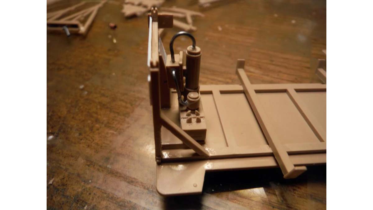
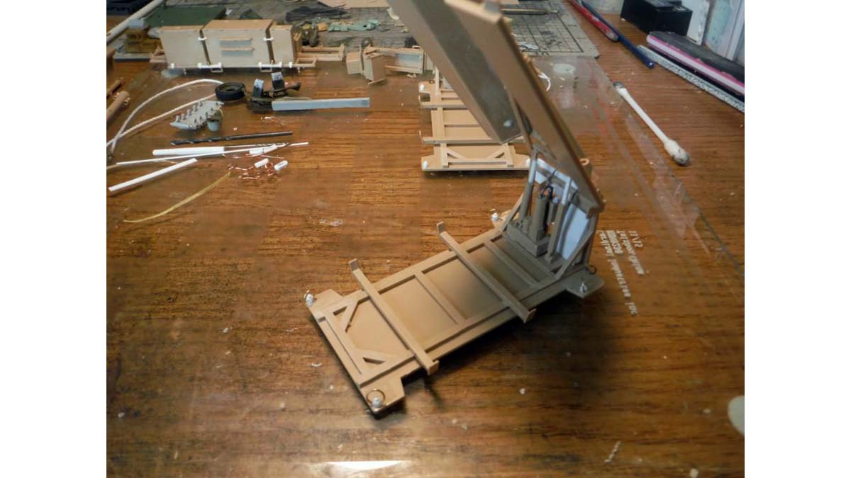
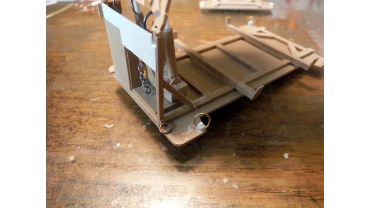
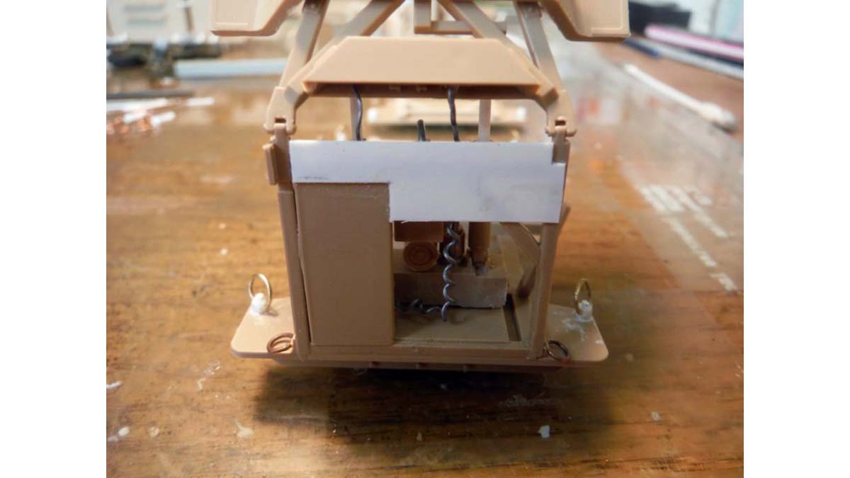
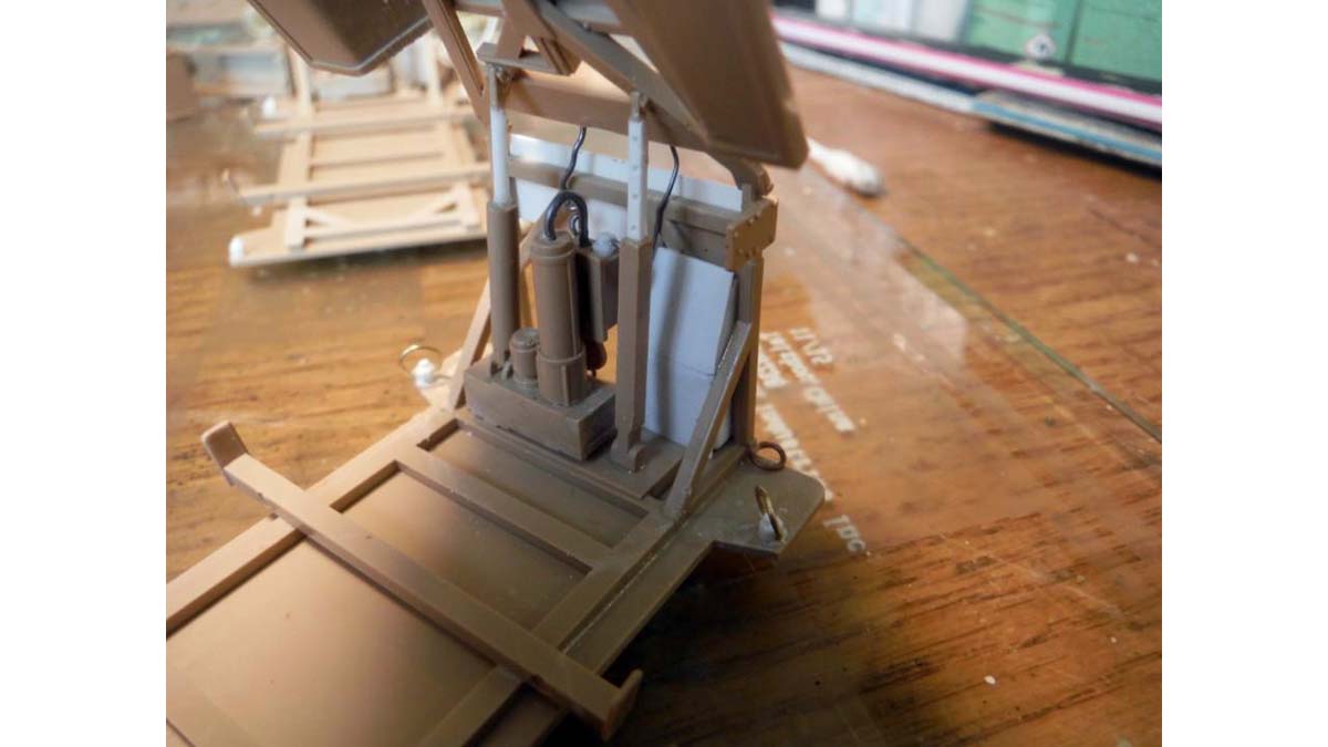
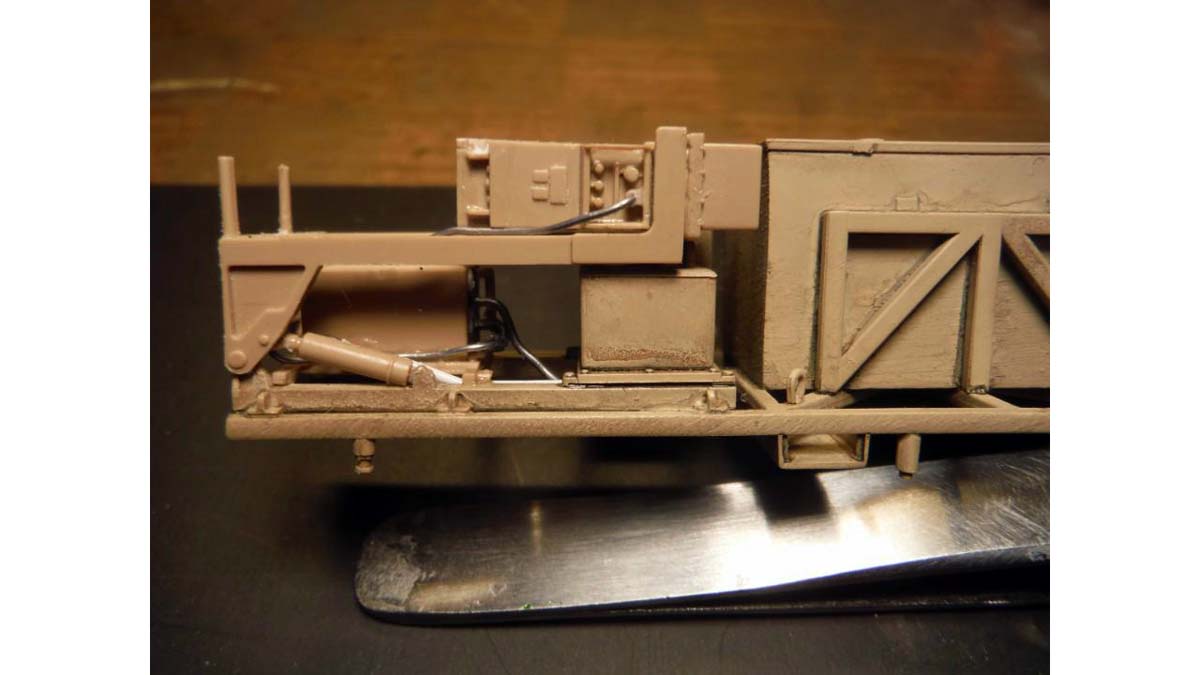
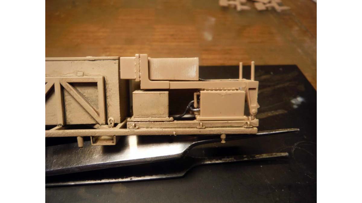
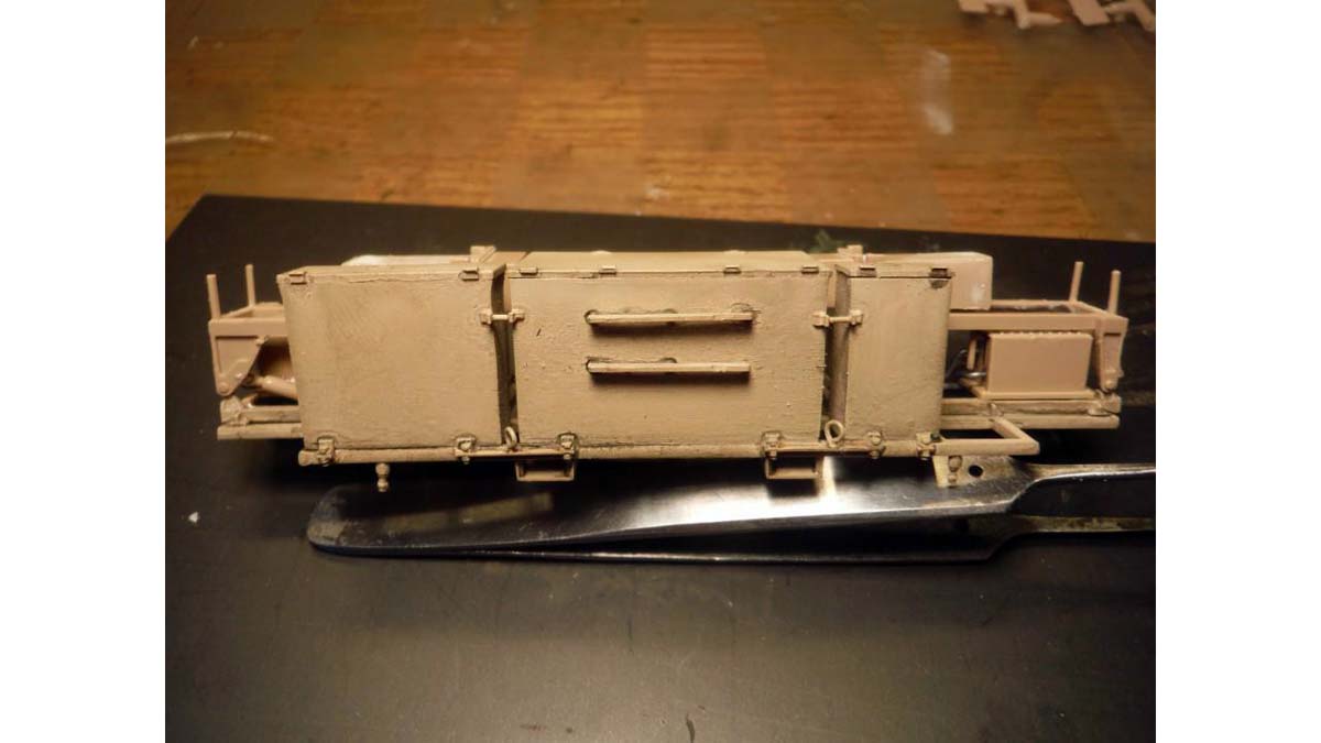
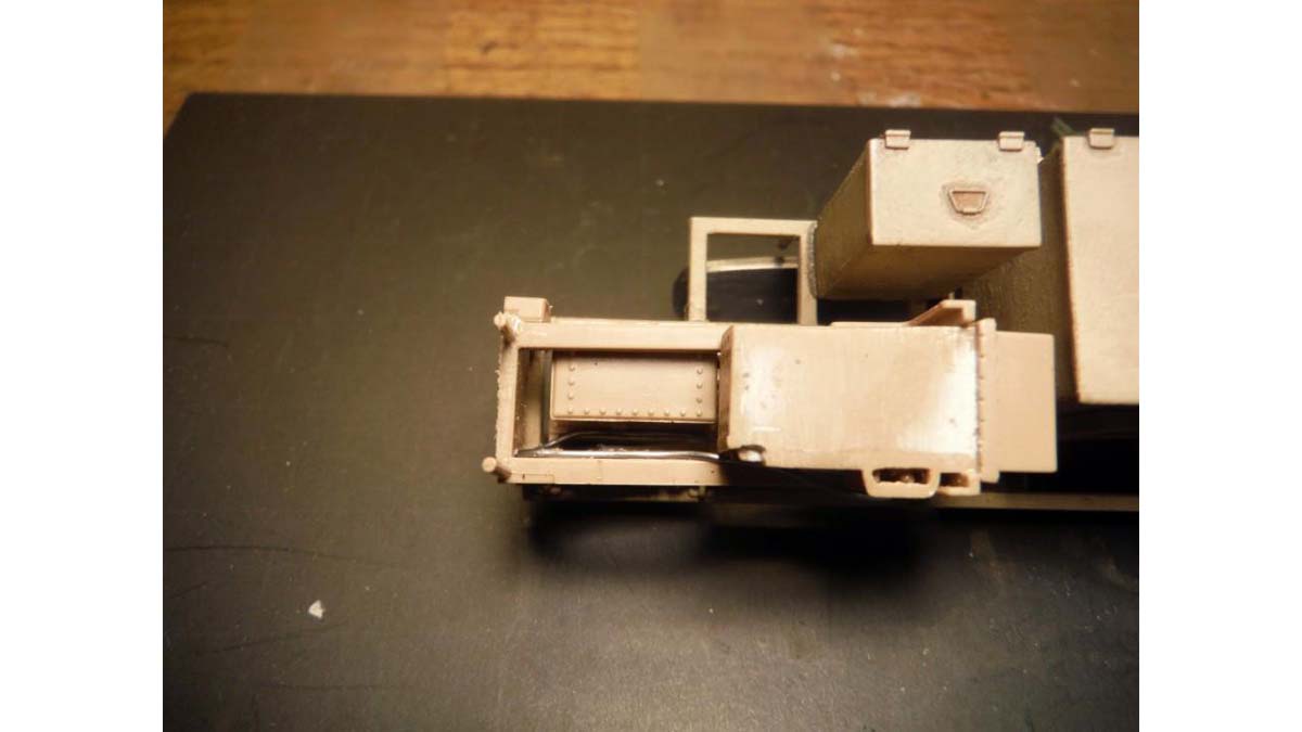
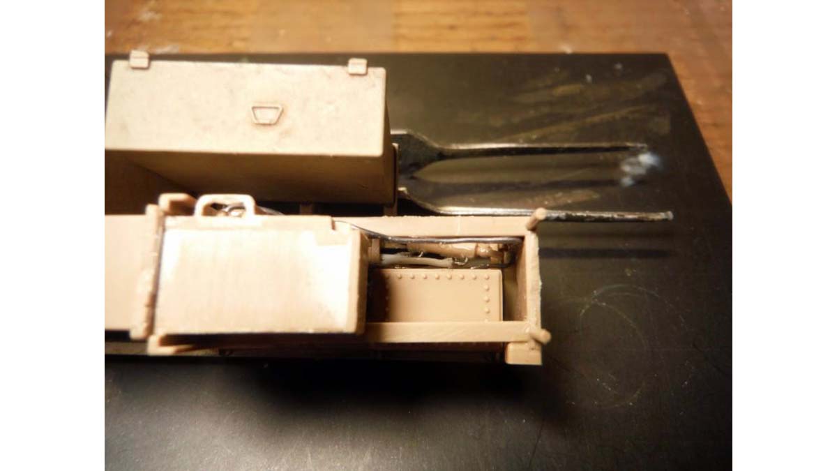
I started with the mounting plate that the plow attaches to and then attached this to the front of the hull. On the back of the main plate, it is open and on the real thing it is not. I used some thin Evergreen plastic sheet to cover up the open back. On the back is also a hydraulic relay block that supplies the hydraulic fluid to the hydraulic arms on the plow. This was made from thin lead wire and plastic stock. Next is the hydraulics that are mounted to the front of the hull. Another relay block is mounted to the front to supply fluid to the arms that lift the plow off the front of the hull. Same wire and plastic stock was used here also. Last added addition to the hull is a conduit located on the right and left rear engine deck. These conduits protect the power cables to the Mine Marking System. I used Evergreen round stock drilled out for this. Wire will be added right before I mount the marking system.
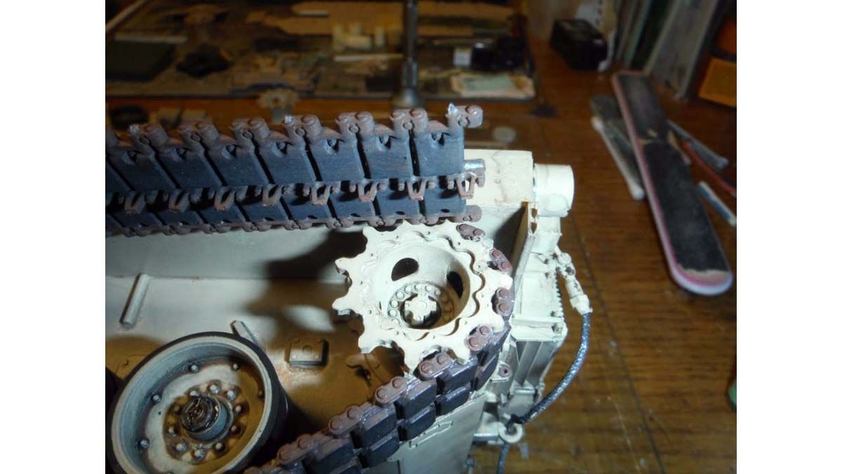
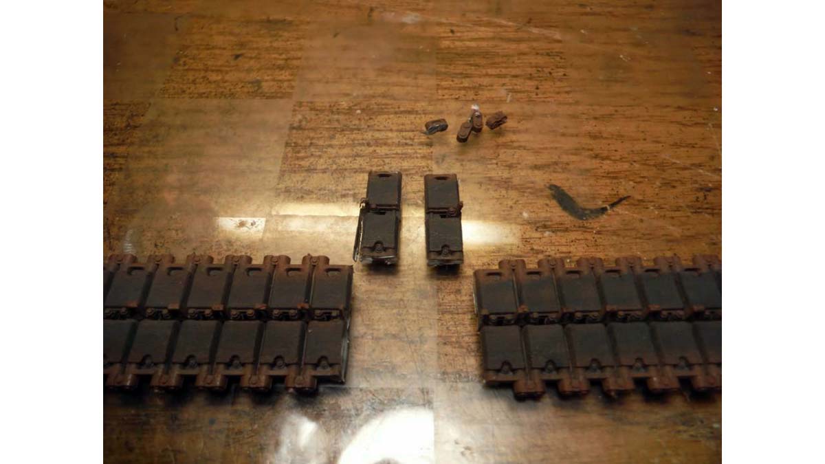
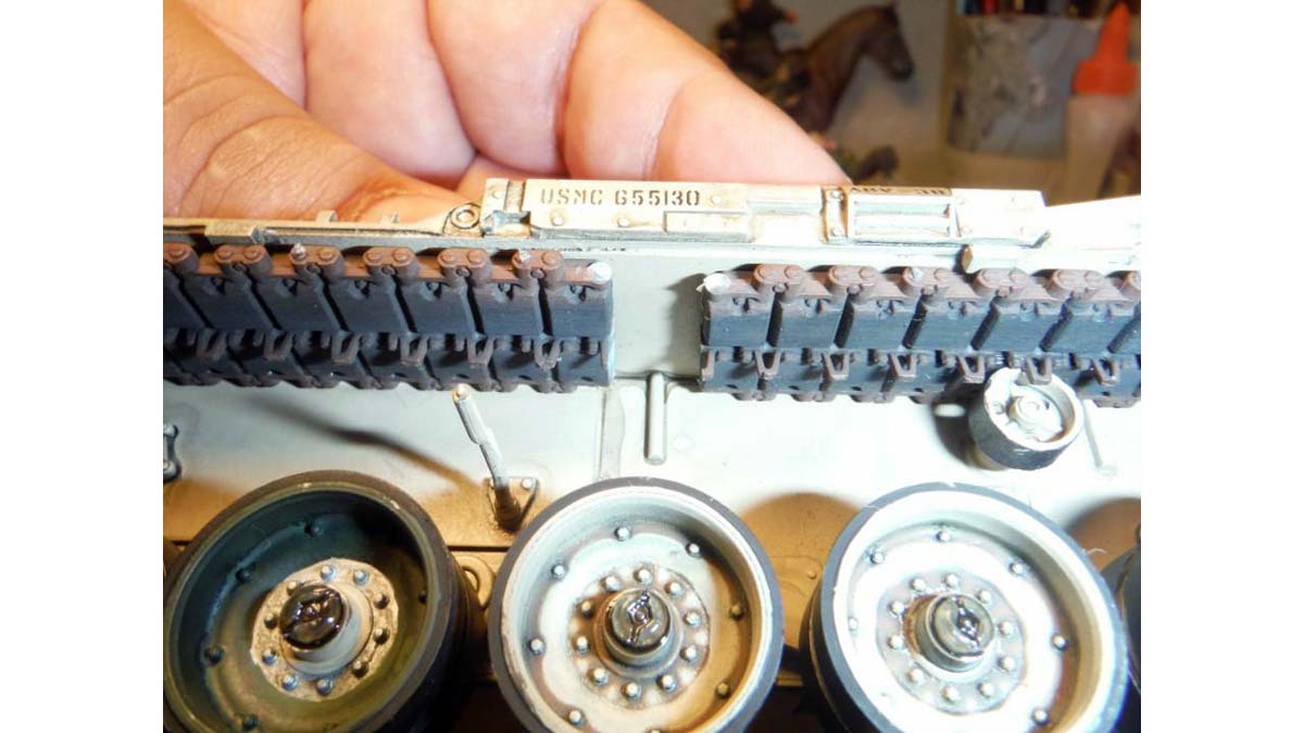
Here is where I ran in to the only issue I had with the kit, the tracks. The top length, part M3x2, are too long. The easiest fix is to just leave off the top length since it won't be seen behind the skirts. But I chose to fix the issue rather than hide it. What I did was cut the two middle tracks and glued the two lengths to the drive sprocket and idler wheel. This worked out perfectly and you can't even see the cut behind the skirts.
I really didn't follow the number sequence in the instructions as you can see, so this time I jumped to the bins attached the "Lane Marking" frame. The connection points that bolt down the bins to the frame and connect them together are ok, but I wanted them to be well defined. I removed them and replaced them with angled plastic stock, rod, and hex rod for the bolt heads.
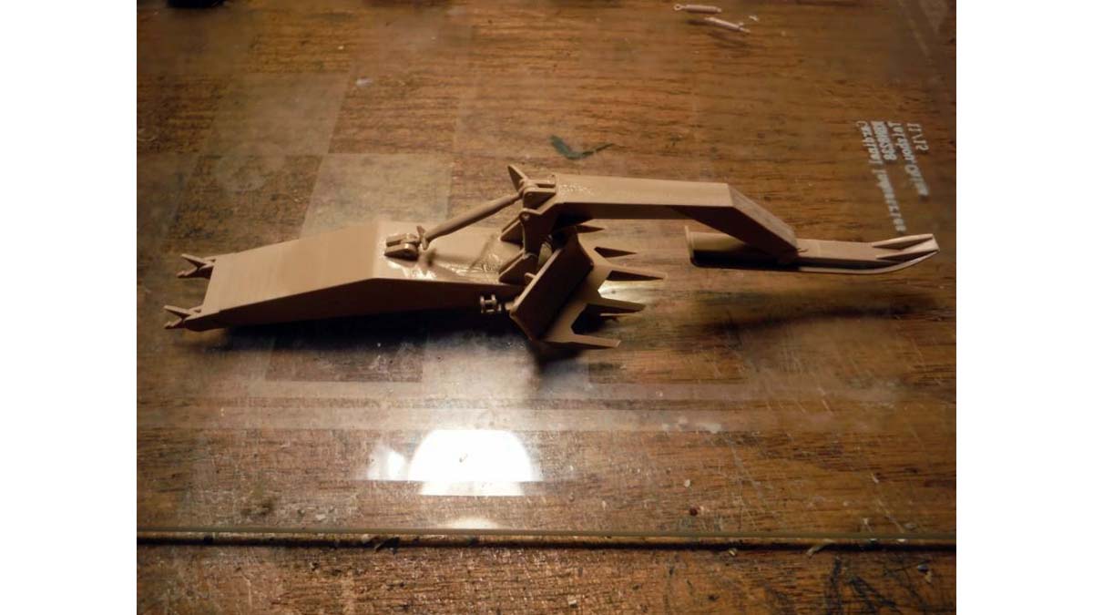
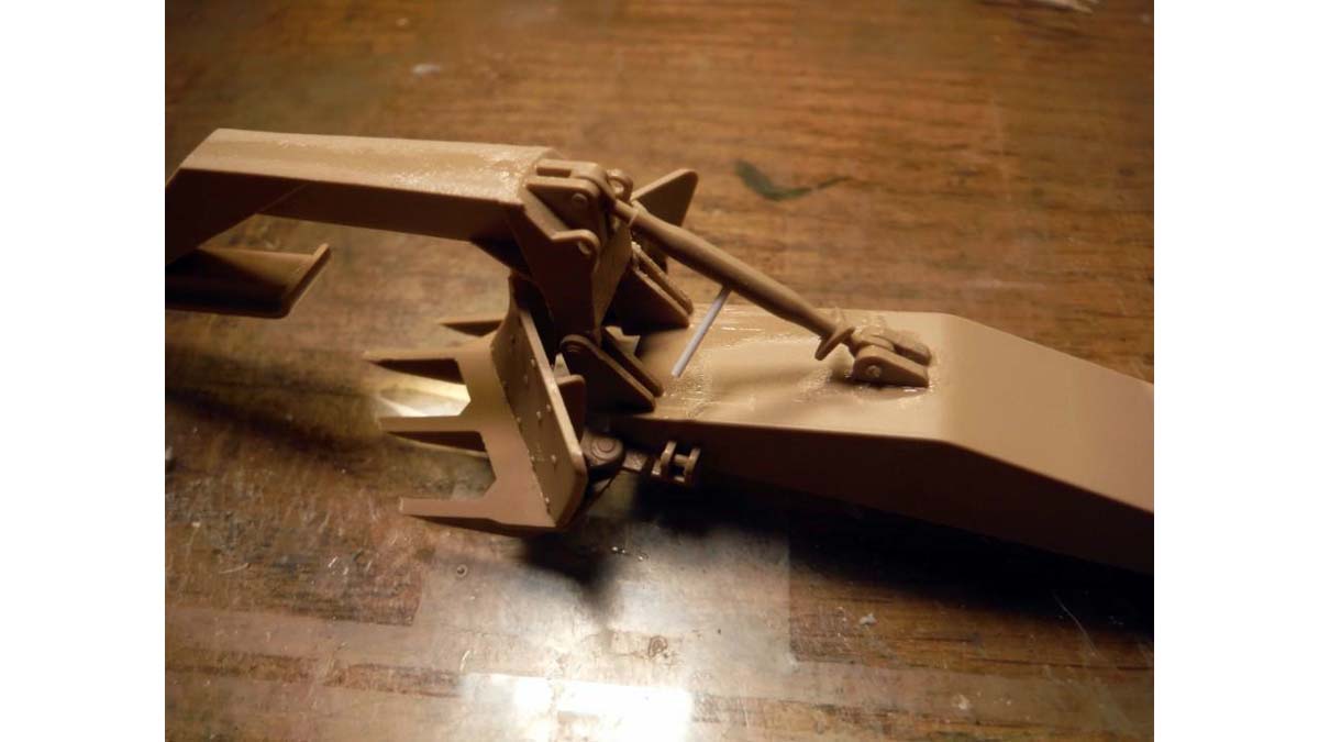
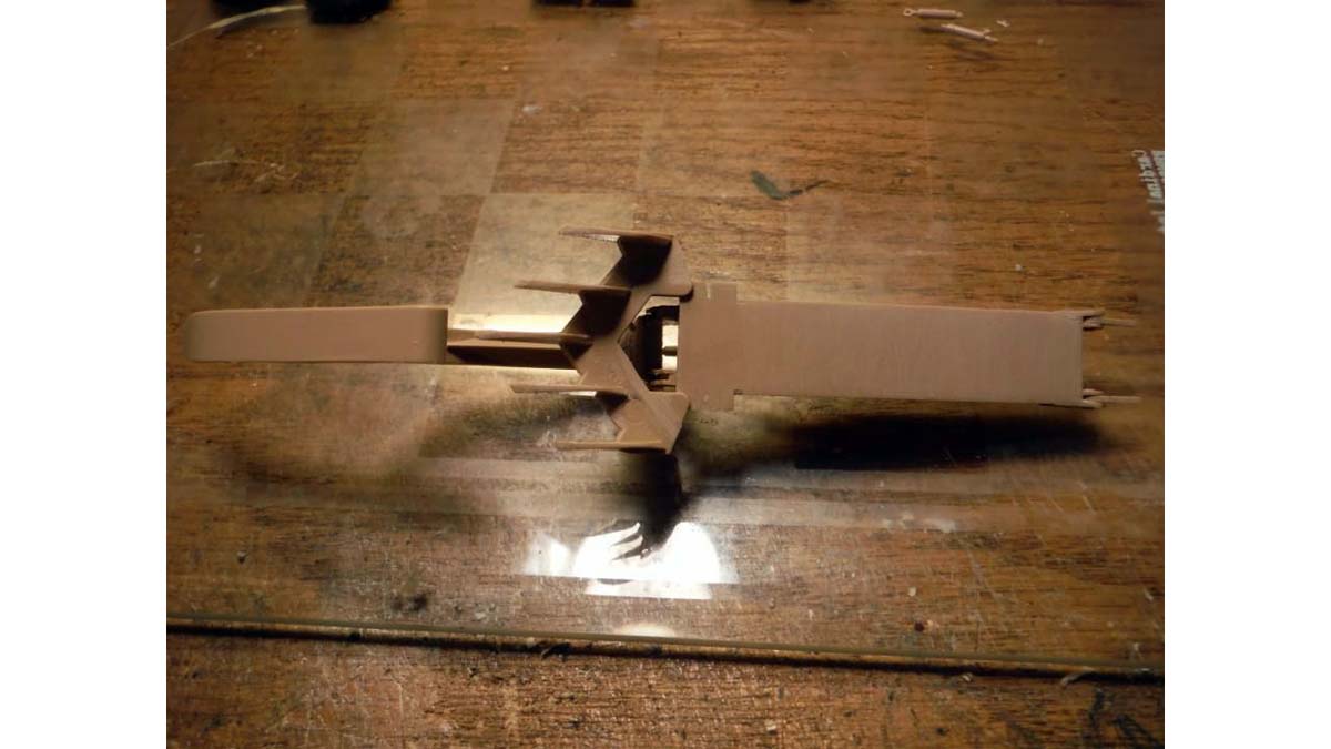
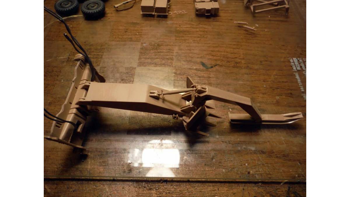
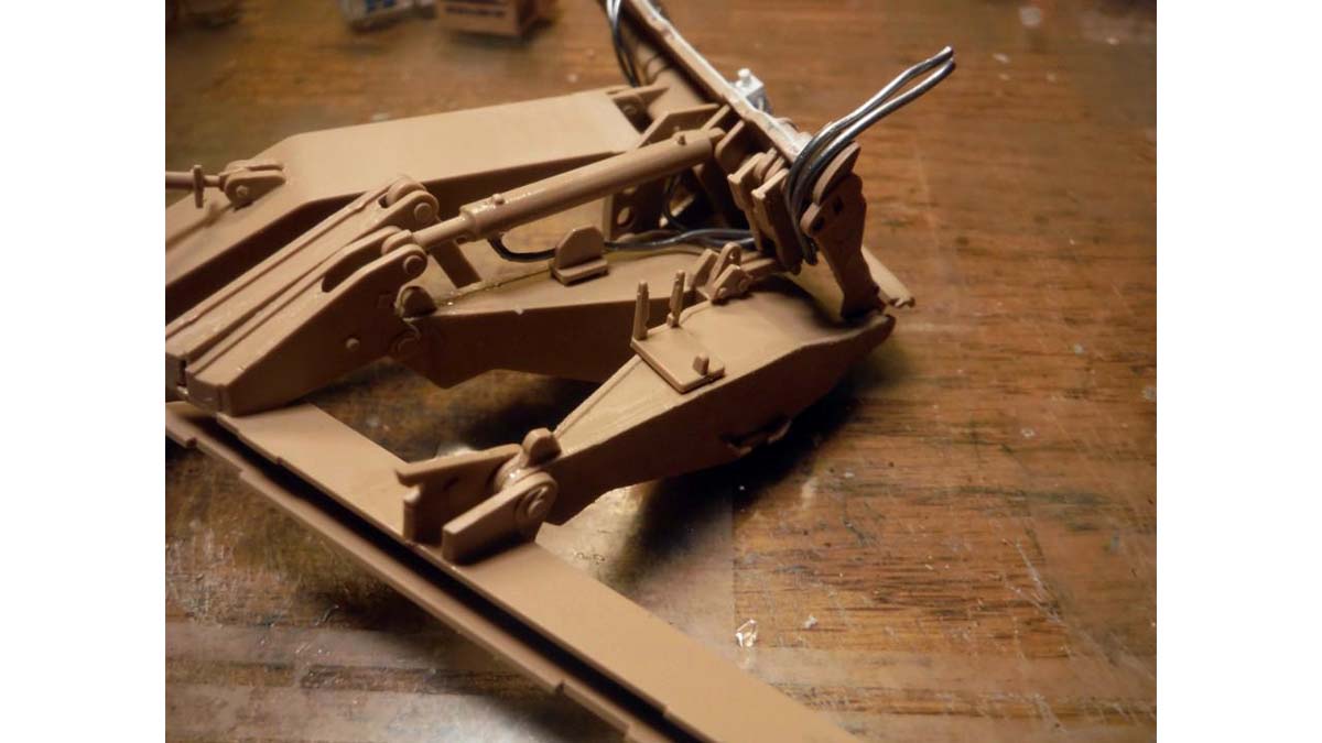
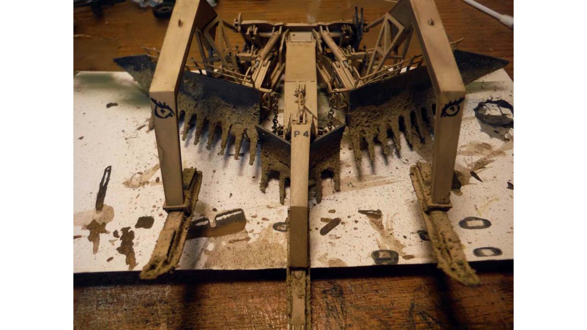
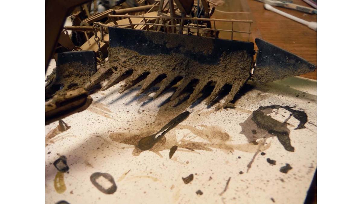
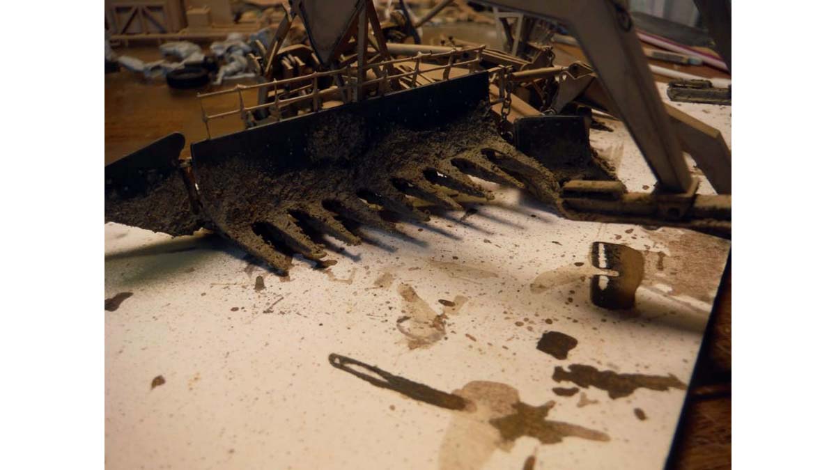
Next, I jumped to the plow itself. I apologize for not taking to many in-progress pictures of the plow. I don't know what I was thinking and went ahead and painted it right after building it. The whole plow and blade can be movable if you take your time and watch you glue placement. I started with the center arm first and attached it the main plate. The only thing I added to the center arm was a bar to help turn the retaining bar. I found it easier to build the main part of the left and right arms. It was also easier to attach the "hoses" to the hydraulic arm. Here is where I stopped taking pictures of the plow build. Again, sorry for that. The blades, part P7(P8) and plow face, part P9(P10) and P11(P12) where attached after the main arm where attached the main plate. I used the diagram in the instruction to mark the placement of photo etch parts V40 - V48. After gluing those parts, I then glued the brass rods to them.
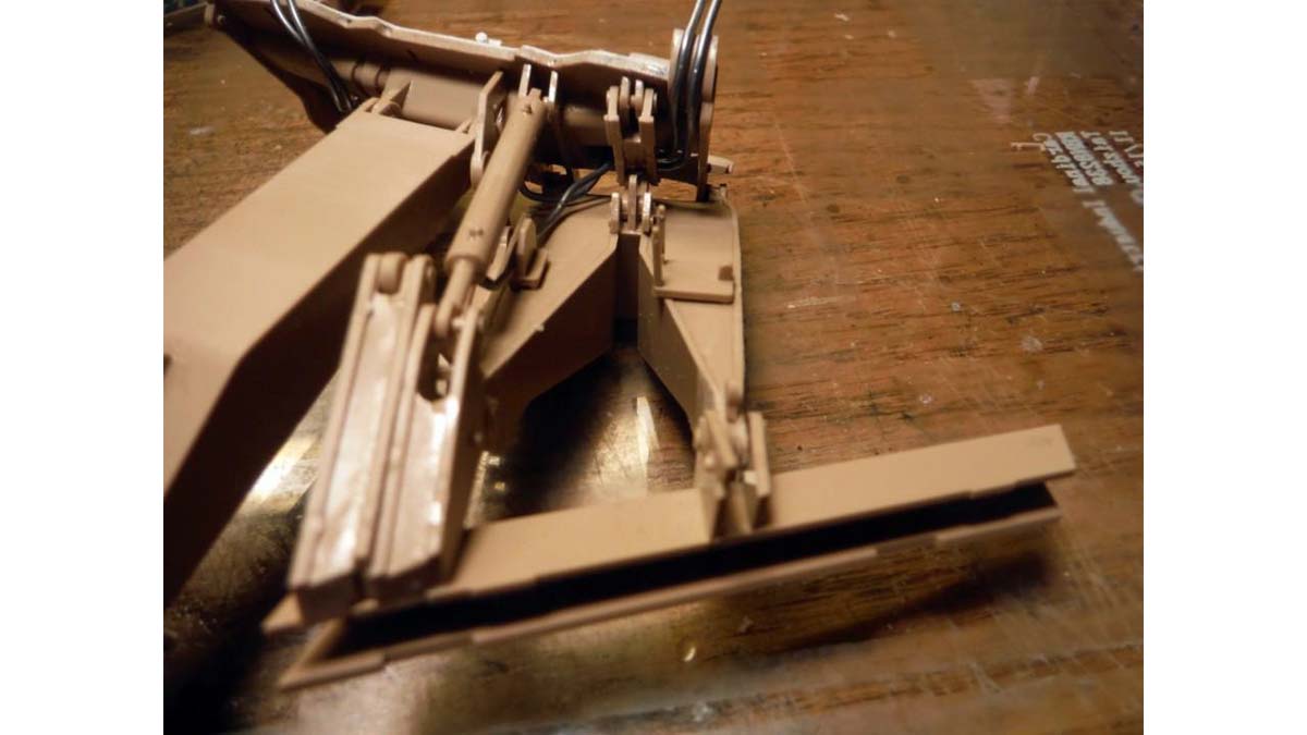
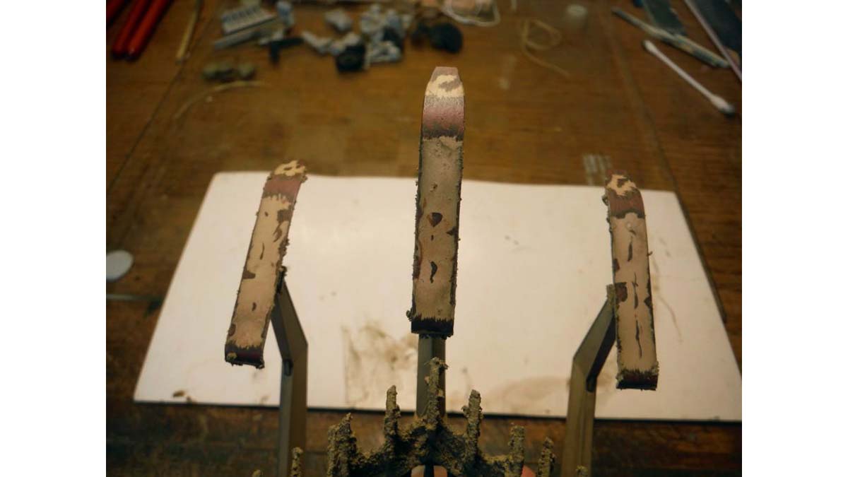
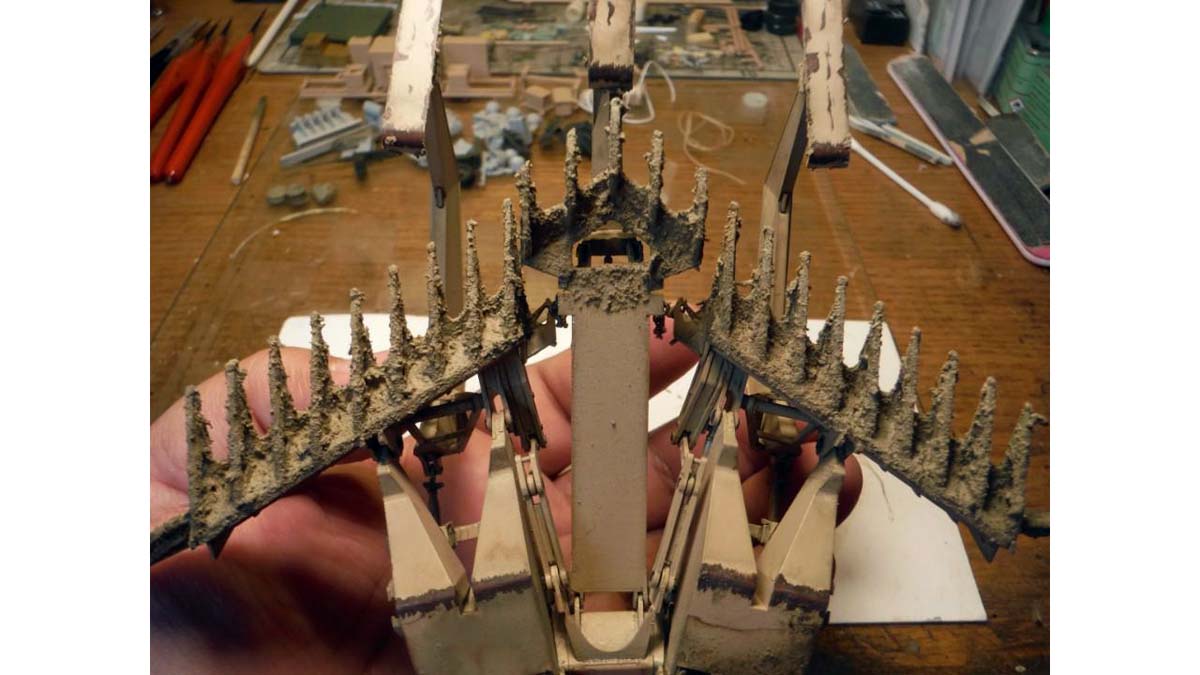
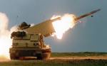
Next are the MICLIC's themselves. Missing hoses and panels where added with lead wire and plastic stock. One of the MICLIC pods was modeled as if just being loaded. The hydraulic arm on the left was replaced with plastic rod and the arm on the right was replaced with plastic square rod to show the lid opened higher. The missing rings on the pods where added using brass wire. The rockets had the missing power cable and wire cable added using lead wire and thin string. The point where the wire cable of the rocket is attached to was replaced with plastic stock and the cable for the line charge added. Black smoke Mig Pigment was added to simulate burnt area from the rocket. Tamiya Clear Orange was used here to simulate to rust found on the real thing. Last was the assembly of the Lane Marking System. Hoses for the hydraulic arm and cables where added using lead wire and thin plastic rod. After the cables and hoses where added, I attached the spikes, painted and weathered the system and bins and then attached it to the rear deck of the hull.


About the Author


FROM: TEXAS, UNITED STATES
I am 48 years of age. I have been modeling since I was around 8 years old. As you can see from my signature, I am retired from the US Army and Texas Army National Guard. I served 6 years in active duty from 1989 to 1995 and in 1998 I joined the Texas Army National Guard and been serving up unt...
Comments


Great job, Pete. She came out looking awesome. Good article with lots of great tips too. I will have to reference it when I build mine.
OCT 29, 2017 - 11:41 PM
Copyright ©2021 by Pete Becerra. Images and/or videos also by copyright holder unless otherwise noted. The views and opinions expressed herein are solely the views and opinions of the authors and/or contributors to this Web site and do not necessarily represent the views and/or opinions of Armorama, KitMaker Network, or Silver Star Enterrpises. All rights reserved. Originally published on: 2017-10-28 16:10:17. Unique Reads: 23701

WEB HOSTING BY


Copyright ©2021 Armorama and Kitmaker Network, a subsidiary of Silver Star Enterprises
All Rights Reserved. Please read our Conditions of Use and Privacy Policy.
All Rights Reserved. Please read our Conditions of Use and Privacy Policy.