M1117 Guardian ASV Review
In this blog, I will illustrate my experience with this kit step-by-step. I'm not knowledgeable enough to tell you that a part is too short, the wrong shape, etc. so I'm not going to do that here. What I will do here, is try to express my joys, frustrations, challenges and what worked or what didn't. So, maybe after this blog is done, we have all had a good time and I've successfully completed another kit.
Try to tolerate my inconsistent photography. Hopefully I can take quality photo's throughout this project. However, I have about 39 days to complete this build for the MP Campaign, 8 days of which I will be in Japan. I plan to move fairly quickly through this project which will minimize how much time I can spend taking repetitive photographs.
Here we go.
Step 1. This step has you building the wheel hubs/rims (A41, A42, A36) and a couple of other parts (parts A22,A3 and A55,A3) that attach to the backside of the wheel hubs/rims.
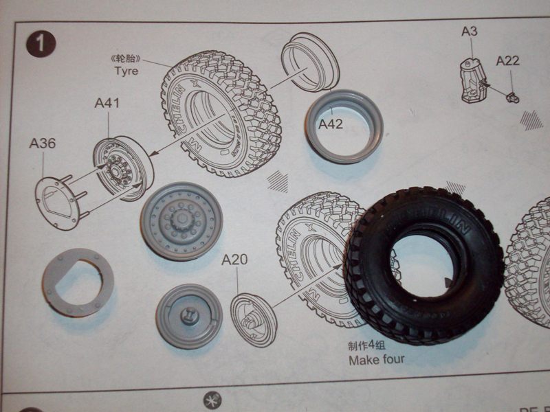
Be careful when removing the molding brace from the inside of each A42 (see review images).
When attaching parts A36 to A41, I highly recommend dry fitting them together. There are 5 pins on the backside of A36 that line up with holes in A41 in a unique pattern. The dry fitting is important to ensure that your pins on A36 line up with the holes correctly on A41 and to ensure your pins all sit at the same depth in A41. If your pins dont all sit at the same depth on A41, A36 will not sit parallel to the hub like it should.
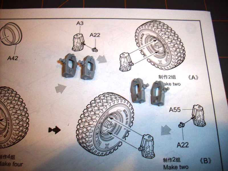
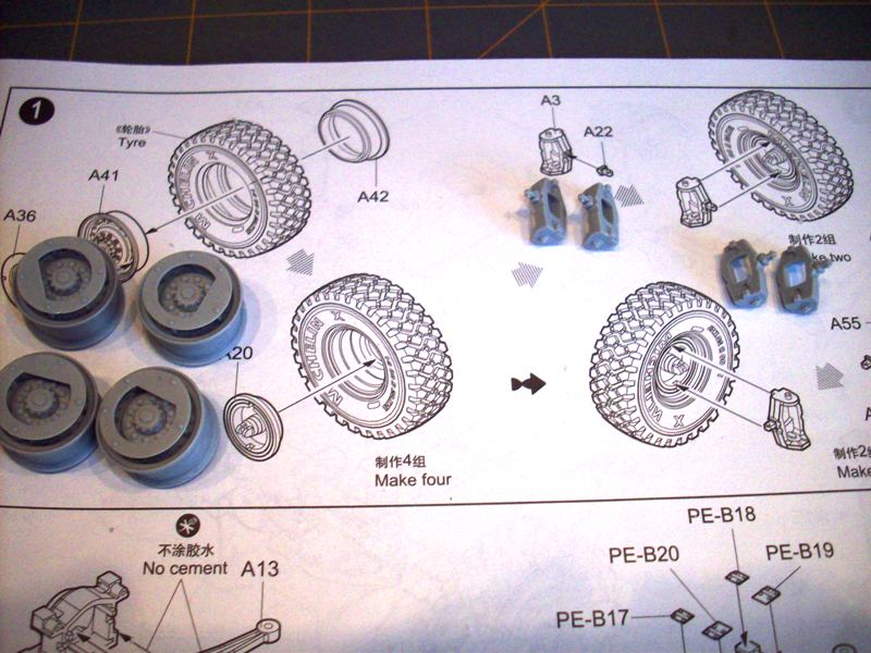
All parts in this step fit well overall. Minor mold seam clean up was required on all parts.
Step 2 This step has you assembling what I believe are transmission housings (A37, A38) and suspension arms (A12, A13). It is very difficult to tell the orientation of the suspension arms in the illustrations. I made a best guess and will find out later on in construction if I was right or not.
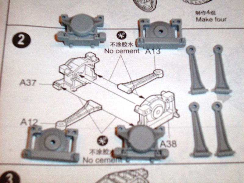
Additional detail is provide by parts A11, A1, A2 and PE B17, B18, B19 and B20. You build a total of two transmission/suspension arm assemblies in the step.
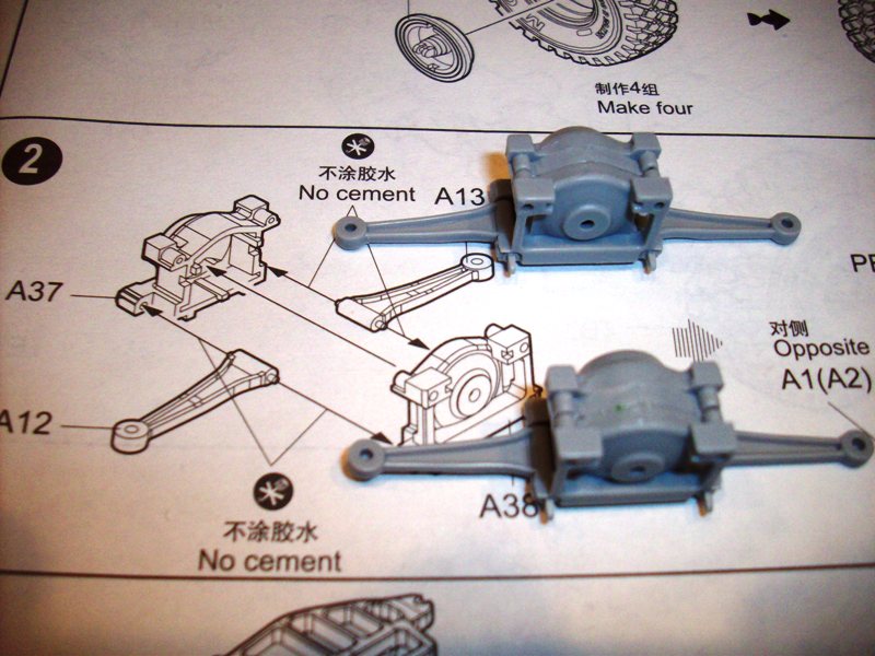
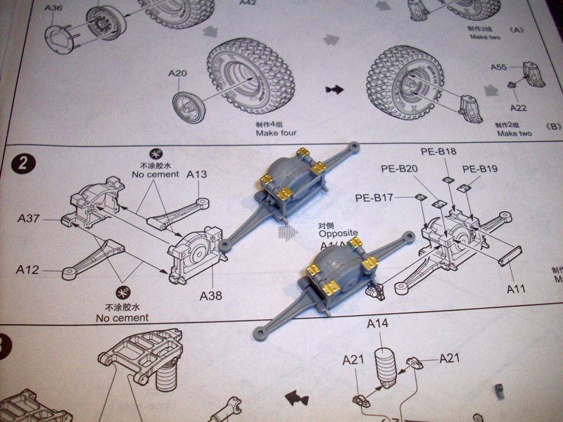
Points of confusion in this step is the lack of alignment pins in the top of either A37 or A38 to align the parts with each other. After assembly of each A37,A38 you have a noticeable gap between the existing alignment holes, but since there is not any alignment pins molded, there is a gap. Nothing a little filler wont fix.
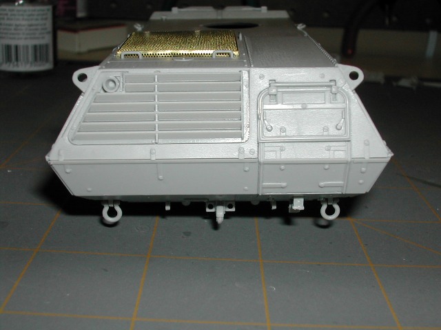
Step 3 This step has you assembling what they later refer to as subassembly D which is the rear axle/drive train assembly. This step overall has to have been one of the hardest assemblies I have ever done.
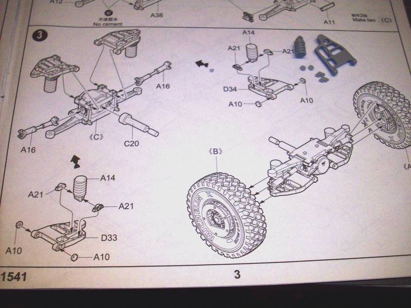
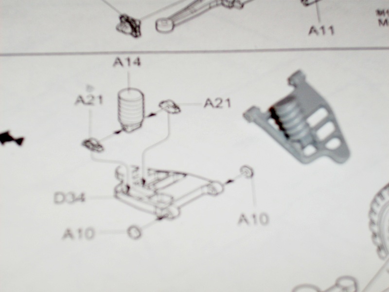
The first significant challenge was getting parts A21 to adhere in place on parts D33 and D34. For whatever reason, these parts were continually coming loose.
The second, and hardest, part of the assembly was getting parts A12, A13 (from step 2), parts A16 and parts D33, D34 to glue into place accordingly, and simultaneously, on the interior of the wheel hubs. There is significant movement of parts D33, D34 and parts A12, A13 during this step because they are not glued in place.
Alignment of all parts on each side while the glue is drying is challenging as well. I wont know if my efforts are successful until Step 11 when the axle/drive train assembly is installed on the vehicle hull. The key to my success will be at the end of construction and seeing that all 4 wheels are level.
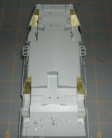
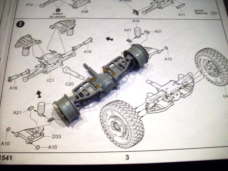
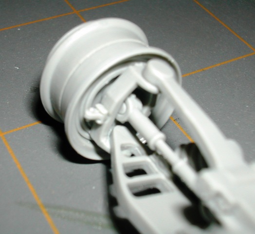
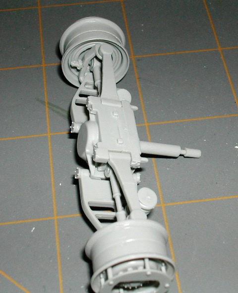
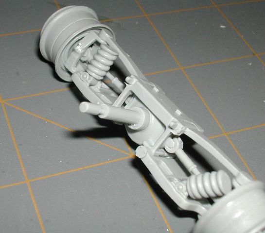
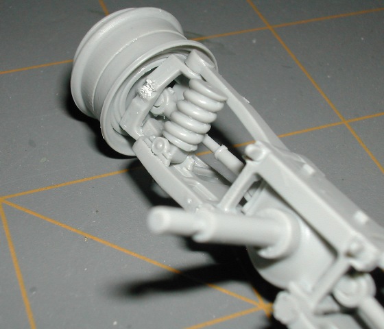
ADDED MARCH 20th AXLE DETAIL
I have had a couple of requests for closer shots of the axles due to confusion in the instruction layout. I only have one axle complete right now. After I get the second axle complete, I will come back, add more photo's and update this text. For now, here are a few closer pictures of the complete axle.
STAY TUNED.....MORE TO COME.....