

Welcome all, I am doing my very first ever build log so I hope you help out as I go! If I get too "wordy " let me know. i will try and let pictures do the talking.
subject matter is the ASLAV F conversion from Mouse House Enterprises Australia. It requires the trumpeter LAV-R as a donor kit (hull/ suspension and crane). The resin conversion consists of over 250 parts, including photo etch and bulged wheels, the deck is a single casting that will save alot of time and already has the anti slip surface applied! there are several threads on armorama that discuss this kit already.
reference : i will be using the fore mentioned threads as they have great photos, the book "military briefs number 4 - ASLAV' by John Myszka. plus the internet. The model will be part of a diorama in progress, and as such will be build not as a shelf queen, but something that will have battle damage/ weathering etc.
I dont always follow the sequence of the instructions, and may do sub assemblies in such a way that allows glue or filler to dry overnight and progress to other assemblies in the mean time - so blog might jump around a bit but will try to keep it obvious what is happening!
wish me luck. if you are following this blog to help with your own build - please contibute any corrections, errors or omissions - I invite them with gusto!
Adam
Hosted by Darren Baker
ASLAV F (Fitters) Build log, Iraq 2006
Adamskii

Joined: November 06, 2010
KitMaker: 537 posts
Armorama: 474 posts

Posted: Saturday, December 25, 2010 - 10:54 PM UTC
Adamskii
Joined: November 06, 2010
KitMaker: 537 posts
Armorama: 474 posts
Posted: Saturday, December 25, 2010 - 11:01 PM UTC
Ok firstly here are the tools I use to build. I use 3 kinds of adh, 2 cyano - one very thin (like water), one very thick (gel like) and tamiya extra thin for the plasic parts. i use a zip kicker to cure the stuff that needs instant fix. the other tools most modellers would have as a minimum!
I tip all the parts from the resin kit into a foil bbq tray, so i can see them laid out, as i build sub assemblies, I will place them in a tackle box.


I tip all the parts from the resin kit into a foil bbq tray, so i can see them laid out, as i build sub assemblies, I will place them in a tackle box.
Adamskii
Joined: November 06, 2010
KitMaker: 537 posts
Armorama: 474 posts
Posted: Saturday, December 25, 2010 - 11:07 PM UTC
first up i went for the main assembly - I like the big block to be one piece first - if things dont fit and i have to sand and fill , I prefer to not have to work around delicate parts that may be glued on already (such as the prop blades, suspension and steering).
fitting the top to the hull requires alot of test fitting and sanding


the 4 sockets for the front suspension sit higher on the hull tha the edge, and although the top has some area in the casting already removed so as not to foul them when they mate, i found they did. So i sanded the 4 sockets down flush with the top edge of the hull, and took some of the "meat" away from the resin casting


fitting the top to the hull requires alot of test fitting and sanding
the 4 sockets for the front suspension sit higher on the hull tha the edge, and although the top has some area in the casting already removed so as not to foul them when they mate, i found they did. So i sanded the 4 sockets down flush with the top edge of the hull, and took some of the "meat" away from the resin casting
Adamskii
Joined: November 06, 2010
KitMaker: 537 posts
Armorama: 474 posts
Posted: Saturday, December 25, 2010 - 11:16 PM UTC
The rear hatch door is a bit of work to fit. Firstly you need to be carefull in interpretting what is hull and what is casting flash. Having cut the main riser away earlier we can focus on the inside of the hull. There is a bevelled edge designed to mate with the bevelled edge of the door. In the casting process there may be some warping or whatever so test fitting here is a must.
In the first pic I show cutting the riser plugs away from the bevel - it then needs to sanded smooth - best done with a sanding stick, the vertical bevels caught me out - I thought the burr was part of the hull and couldnt get a proper fit until I trimmed it back. This has the added bonus of making the length of the hull the same as the mating lower half ( it hung over by about .75 of a mm before)
The yellow line is parralel with the Burr (linked to line) I trimmed the burr keeping the blade at the same angle as the burr.


Alot of trimming and sanding to make this door fit!

Once it all fits reasonable well, I like to tape the major parts together with tamiya tape to check for fit.

Once happy with the fit I use my extra thin cyano (superglue) to run along the joins. let cure and remove tape. The rear hatch pics are at this stage with tape removed. I sanded a little around the joins but havent added any filler yet to get it perfect. I am quite pleased with its fit! Will do the edges of the hull next.

In the first pic I show cutting the riser plugs away from the bevel - it then needs to sanded smooth - best done with a sanding stick, the vertical bevels caught me out - I thought the burr was part of the hull and couldnt get a proper fit until I trimmed it back. This has the added bonus of making the length of the hull the same as the mating lower half ( it hung over by about .75 of a mm before)
The yellow line is parralel with the Burr (linked to line) I trimmed the burr keeping the blade at the same angle as the burr.
Alot of trimming and sanding to make this door fit!
Once it all fits reasonable well, I like to tape the major parts together with tamiya tape to check for fit.
Once happy with the fit I use my extra thin cyano (superglue) to run along the joins. let cure and remove tape. The rear hatch pics are at this stage with tape removed. I sanded a little around the joins but havent added any filler yet to get it perfect. I am quite pleased with its fit! Will do the edges of the hull next.
Adamskii
Joined: November 06, 2010
KitMaker: 537 posts
Armorama: 474 posts
Posted: Sunday, December 26, 2010 - 12:35 AM UTC
spot the colossal screw up error i made - you get a gold star. (error rectified now I seen it). No hints.
Adamskii
Joined: November 06, 2010
KitMaker: 537 posts
Armorama: 474 posts
Posted: Sunday, December 26, 2010 - 04:41 AM UTC
Ok the steering. this part you have to make a decision - do you want the wheels turned ? Remembr this, that on the ASLAV / LAV FOV (family of vehicles), however much the front wheels turn, the second pair turn half as much. So if the front wheels are turned 30 degrees, the second pair at the front are 15 degrees.
The method I use is a simple one, it does not replicate the truth of how the steering linkages work, but is ok for a diorama model where the linkages will not be able to be examined (as with a shelf queen or static model). It works best on shallow turns, as aggresive wheel turning introduces problems of clearance between parts.
firstly, assemble the suspension yokes x4, do not glue the hinges in place. work out the direction of the turn. the hull has a half moon shaped hole, and the struct tht mounts in it has a matching shape, here is first trick, trim the angle of the turn you desire from the structs pin - allowing it to rotate ever so slighly in the crescent hole. do this for all 4 structs. then flip the yokes back onto its corresponding struct pin. Do take the time to think about what direction they turn and whether it is a left or right struct. Firts time I done this I forgot that when working upside down they turn opposite to what I want. Here's some pics to help

In this pic we see my front wheel are turning angle "A", and the pair behind are only turning half of "A". the centerline is the purple on marked C.

now we attach the steering linkage assembly. I find it easier to do the surgery on the vehicle than on the bench. I dont glue the assembly in place as it is a very tight fit in the locating holes and wont budge easy.

In the following pic I start to trim down the right side tie arm (too long)

The bush is attached to the struct, and the shortened rod glued back onto the steering linkage.

the left side of the vehicle needs a longer tie rod, so I cut away the short part, remove and discard the Tie rod, glue the bush back onto the struct.


Then measure the gap between the bush and linkage, cut a 1mm diameter length of rod to fit between them


Just in case you confused by what names I am calling the parts heres an explanation pic

just a quick note on some of the smaller parts - Trumpeter in their wisdom moulded some stuff in very silly places. So what i do with these tiny parts is instead of cleaning them up on the workbench, I cut them from sprue, with tweezers I dip mating surface in glue, attach to the hull, let it dry, and then sand the sprue away. this way the part is quite secure on the model and wont get lost easy. sand gently of course. hope this tip helps !

The method I use is a simple one, it does not replicate the truth of how the steering linkages work, but is ok for a diorama model where the linkages will not be able to be examined (as with a shelf queen or static model). It works best on shallow turns, as aggresive wheel turning introduces problems of clearance between parts.
firstly, assemble the suspension yokes x4, do not glue the hinges in place. work out the direction of the turn. the hull has a half moon shaped hole, and the struct tht mounts in it has a matching shape, here is first trick, trim the angle of the turn you desire from the structs pin - allowing it to rotate ever so slighly in the crescent hole. do this for all 4 structs. then flip the yokes back onto its corresponding struct pin. Do take the time to think about what direction they turn and whether it is a left or right struct. Firts time I done this I forgot that when working upside down they turn opposite to what I want. Here's some pics to help
In this pic we see my front wheel are turning angle "A", and the pair behind are only turning half of "A". the centerline is the purple on marked C.
now we attach the steering linkage assembly. I find it easier to do the surgery on the vehicle than on the bench. I dont glue the assembly in place as it is a very tight fit in the locating holes and wont budge easy.
In the following pic I start to trim down the right side tie arm (too long)
The bush is attached to the struct, and the shortened rod glued back onto the steering linkage.
the left side of the vehicle needs a longer tie rod, so I cut away the short part, remove and discard the Tie rod, glue the bush back onto the struct.
Then measure the gap between the bush and linkage, cut a 1mm diameter length of rod to fit between them
Just in case you confused by what names I am calling the parts heres an explanation pic
just a quick note on some of the smaller parts - Trumpeter in their wisdom moulded some stuff in very silly places. So what i do with these tiny parts is instead of cleaning them up on the workbench, I cut them from sprue, with tweezers I dip mating surface in glue, attach to the hull, let it dry, and then sand the sprue away. this way the part is quite secure on the model and wont get lost easy. sand gently of course. hope this tip helps !

sauceman

Joined: September 28, 2006
KitMaker: 2,672 posts
Armorama: 2,475 posts

Posted: Sunday, December 26, 2010 - 05:11 AM UTC
Nicely detailed blog so far, it takes alot of behind the workbench work to explain it all with power type slides, good work!
cheers
cheers

C_JACQUEMONT

Joined: October 09, 2004
KitMaker: 2,433 posts
Armorama: 2,325 posts

Posted: Sunday, December 26, 2010 - 09:09 AM UTC
Great blog! 
I'm interested in this vehicle but was waiting for a proper review, after all, if I'm not mistaken, the resin conversion costs $130 (Australian) or about 100 ! A blog is even better than a review of course.
Cheers,
Christophe
I'm interested in this vehicle but was waiting for a proper review, after all, if I'm not mistaken, the resin conversion costs $130 (Australian) or about 100 ! A blog is even better than a review of course.
Cheers,
Christophe
Adamskii
Joined: November 06, 2010
KitMaker: 537 posts
Armorama: 474 posts
Posted: Sunday, December 26, 2010 - 11:33 AM UTC
Bonjour Christophe! Thankyou for the comments.
Some notes to add in reflection of yesterdays work.
First yes i didnt realise that for every 10 minutes spent modelling, 5 mins is spent doing the blog (just as you suggest Rick). Model notes : I have barely touched the resin conversion yet, most of its just trumpeters lower hull, hope to get into the meaty stuff today (after I clean the pool again, go to the shops, entertain the post Xmas guests etc).
Also i should of pointed out the wheels on the kit are intended to face forward and are not meant to be turned. And the model I am building is for use in the Al muthana task group(AMTG) one of Australias contributions to OIF in Iraq circa 2006. The diorama it will be going on is a street patrol with 2 oth ASLAV variants ( a kind of show and tell of Aussie armour in Iraq).
Enjoy.

jasmils
Joined: December 23, 2003
KitMaker: 1,016 posts
Armorama: 745 posts

Posted: Sunday, December 26, 2010 - 01:31 PM UTC
Quoted Text
spot the colossal screw up error i made - you get a gold star. (error rectified now I seen it). No hints.
Can I say, cool blog Adam.
As for the mistake, I will leave to some one else.
Nah I won't, you used the wrong lower hull.
But in saying that, not to hard to fix it up.
Cheers Jason
Adamskii
Joined: November 06, 2010
KitMaker: 537 posts
Armorama: 474 posts
Posted: Sunday, December 26, 2010 - 01:47 PM UTC
Gold star for Jason.
I sanded the lower hull as described, then wanted to do a comparison picture with the normal hull - took pick with them side by side, picked up wrong hull next time and without thinking sanded a bit more and it fitted - glued it, bogged it, admired it and then almost threw up when I seen it. santa wont be impressed by the words from my mouth. That said - its been fixed - a hot knife through plastic. good thing I had the reference hull next to it....
classic Doh! and Insult to injury I didnt like the pic and never used it.
Adamskii
Joined: November 06, 2010
KitMaker: 537 posts
Armorama: 474 posts
Posted: Sunday, December 26, 2010 - 07:44 PM UTC
Moving right along we have the two Hydraulic side stabilizer assemblies. Unique to the fitters vehicle as I understand. Anyways these are very very delicate assemblies. First photo shows what we are trying to achieve (completed assemblies. The rest are how I got there ! I will show building pictures for the left side only - right side is exact copy.

These are the parts used - the blocks with the union joints is super delicate and the parts once removed are easy to break and loose. Be warned !

firstly apply the mounting point and reinforcing rails.


I pre drill the sockets for the little elbows (part FC3) with a 1mm drill bit. I always try to pre drill small thing like this. If I wasnt doing a build log I would toss them and use solder without the elbows, and wrap a single layer of tamiya tape to look like a union. but for the sake of doing it for the build log..


then into the holes attach the 4 elbows - check references for orientation.

attach the struct

now the really hard part - fitting the hydraulic lines (I assume hydraulic and not pneumatic?) cannot pre drill the locating holes in the ends of the elbows - so have to mate them like a butt joint. I pre bend and test fit the piece to be glued (see pic) and then dab one end with a gel glue, hold in place, and spray with a zip kicker (super glue instant cure) then bend / position other end of line to its mating point, and with a toothpick, apply a dab of gel glue to the join. the residual zip kicker will be on the surface and cure instantly!


done
heres another view of the right side.

I love the pic below - shows a fitters being worked on? but can see a tie rod laying on the ground between two front wheels, colours of some of the parts, and a peek at the stabilizer struct assembly. Also uniforms, helmets, spare wheels and other bits useful for in country dio!

Next I have to attach those resin chain locks under the hull - I hate that bit. after dinner maybe...
These are the parts used - the blocks with the union joints is super delicate and the parts once removed are easy to break and loose. Be warned !
firstly apply the mounting point and reinforcing rails.
I pre drill the sockets for the little elbows (part FC3) with a 1mm drill bit. I always try to pre drill small thing like this. If I wasnt doing a build log I would toss them and use solder without the elbows, and wrap a single layer of tamiya tape to look like a union. but for the sake of doing it for the build log..
then into the holes attach the 4 elbows - check references for orientation.
attach the struct
now the really hard part - fitting the hydraulic lines (I assume hydraulic and not pneumatic?) cannot pre drill the locating holes in the ends of the elbows - so have to mate them like a butt joint. I pre bend and test fit the piece to be glued (see pic) and then dab one end with a gel glue, hold in place, and spray with a zip kicker (super glue instant cure) then bend / position other end of line to its mating point, and with a toothpick, apply a dab of gel glue to the join. the residual zip kicker will be on the surface and cure instantly!
done
heres another view of the right side.
I love the pic below - shows a fitters being worked on? but can see a tie rod laying on the ground between two front wheels, colours of some of the parts, and a peek at the stabilizer struct assembly. Also uniforms, helmets, spare wheels and other bits useful for in country dio!
Next I have to attach those resin chain locks under the hull - I hate that bit. after dinner maybe...

sam_dwyer
Joined: November 03, 2008
KitMaker: 294 posts
Armorama: 291 posts
Posted: Sunday, December 26, 2010 - 08:10 PM UTC
Great work so far Adam!
Something you might have missed, there is some slight mold slip on the outrigger arms:

Havent dont squat with my Fitters as yet, still doing the visit family during Xmas break/ignore models thing!
Sam
Something you might have missed, there is some slight mold slip on the outrigger arms:
Havent dont squat with my Fitters as yet, still doing the visit family during Xmas break/ignore models thing!
Sam
Adamskii
Joined: November 06, 2010
KitMaker: 537 posts
Armorama: 474 posts
Posted: Sunday, December 26, 2010 - 09:23 PM UTC
thanks for spotting that - i missed it. The outrigger arms have a square plate on the bottom - on both of mine they were offset a little and need squaring too.
Adam
Adam
grimmo
Joined: January 17, 2006
KitMaker: 752 posts
Armorama: 569 posts
Posted: Sunday, December 26, 2010 - 09:32 PM UTC
Great work Adam! I'll be following yours and sams build as it it happens. I havent ordered mine yet, still a bit short of cash.
specmod
Joined: August 12, 2009
KitMaker: 93 posts
Armorama: 91 posts
Posted: Sunday, December 26, 2010 - 10:18 PM UTC
Mate, your not messing around with this at all, top stuff so far, will continue to watch this one, keep up the great work, cheers

Adamskii
Joined: November 06, 2010
KitMaker: 537 posts
Armorama: 474 posts
Posted: Monday, December 27, 2010 - 03:10 AM UTC
Wheels
I decided to fit the wheels next basically to shield the delicate hoses on the side supports.
Wheels fit very easy and require minimum effort. A few things to keep in mind. All 8 wheels should rest on the ground when the vehicle/ model is on a flat surface. If one sits up in the air, or sits low (raising several off the ground around it) then test fit and make adjustmenst now. Either sand a small amount off a proud wheel, or build up a high one ( I have no idea how, but im sure it could be done). Also dont forget alignment in all 3 dimensions - left and right, up and down, front and back should all be square to each other. I use a little steel rule as a guide. also I use slow cure gel adhesive so i can persuade any off cente wheel to the right spot, and then hit it with zip kicker to cure where it should be.


the next two pics compare the shallow wheel turn on the fitters with a more aggresive turn on the PC. not that the second set of wheels only turns half of what the front set do.


I decided to fit the wheels next basically to shield the delicate hoses on the side supports.
Wheels fit very easy and require minimum effort. A few things to keep in mind. All 8 wheels should rest on the ground when the vehicle/ model is on a flat surface. If one sits up in the air, or sits low (raising several off the ground around it) then test fit and make adjustmenst now. Either sand a small amount off a proud wheel, or build up a high one ( I have no idea how, but im sure it could be done). Also dont forget alignment in all 3 dimensions - left and right, up and down, front and back should all be square to each other. I use a little steel rule as a guide. also I use slow cure gel adhesive so i can persuade any off cente wheel to the right spot, and then hit it with zip kicker to cure where it should be.
the next two pics compare the shallow wheel turn on the fitters with a more aggresive turn on the PC. not that the second set of wheels only turns half of what the front set do.
Adamskii
Joined: November 06, 2010
KitMaker: 537 posts
Armorama: 474 posts
Posted: Monday, December 27, 2010 - 03:26 AM UTC
engine mesh
Fitting the photo etch mesh for the engine covers requires a sharp knife, steel rule and patience - lots of it. First I trim the parts from the fret with sharp knife:

next, after a test fit I trim the mesh 1 line of squares from two sides. (it overhangs by that much) and then cut the thick line of squares out the center of the mesh.


I test fit the front mesh and find the raised bump in the grill wont fit through the hole - so I trim the bump to make it fit , easier to do that than make the hole bigger!

here they are both fitted. if you try to just lay the top mesh over the grill , the raised bar in it will bow the mesh. so either cut/sand the bar or cut the mesh ( I cut the mesh obviously) Also in this pic I have fitted the exhaust.

Now we need to add the bolts.
I have a method where I: A) slice the bolt heads from sprue, B)stab a bolt with sharp blade, C)dip bolt in wet glue ( i put some on bit of scrap plastic), D) place bolt with glue on mesh where I want it to fit, wait a few seconds to dry and pull away the knife.


While at it I add some details to front deck (all from image 1 in instructions)
I pre drill the holes where Im going to put handles with a 1mm drill bit. (yellow lines)

fitting the tie downs is a wretched task. basically toothpic a tiny drop of glue where you want it to go, drop in on top and wiggle around until it sits righ or the glue dries.

Fitting the photo etch mesh for the engine covers requires a sharp knife, steel rule and patience - lots of it. First I trim the parts from the fret with sharp knife:
next, after a test fit I trim the mesh 1 line of squares from two sides. (it overhangs by that much) and then cut the thick line of squares out the center of the mesh.
I test fit the front mesh and find the raised bump in the grill wont fit through the hole - so I trim the bump to make it fit , easier to do that than make the hole bigger!
here they are both fitted. if you try to just lay the top mesh over the grill , the raised bar in it will bow the mesh. so either cut/sand the bar or cut the mesh ( I cut the mesh obviously) Also in this pic I have fitted the exhaust.
Now we need to add the bolts.
I have a method where I: A) slice the bolt heads from sprue, B)stab a bolt with sharp blade, C)dip bolt in wet glue ( i put some on bit of scrap plastic), D) place bolt with glue on mesh where I want it to fit, wait a few seconds to dry and pull away the knife.
While at it I add some details to front deck (all from image 1 in instructions)
I pre drill the holes where Im going to put handles with a 1mm drill bit. (yellow lines)
fitting the tie downs is a wretched task. basically toothpic a tiny drop of glue where you want it to go, drop in on top and wiggle around until it sits righ or the glue dries.
Adamskii
Joined: November 06, 2010
KitMaker: 537 posts
Armorama: 474 posts
Posted: Monday, December 27, 2010 - 03:43 AM UTC
Commanders cupola
i have fitted the closed drivers hatch and few other elements to the deck, but the commanders gun ring is a bit tricky so this is how I went about it.
firstly I glued the resin part on "ch1" this needed a bit of clean up and will need to sit very "flat" as another ring will be mounted over he top !

Next I drilled out all the holes required with a 0.5mm drill bit. These holes will have a piece of rod (supplied in kit) inserted that suspend the gun ring above the resin one just fitted. The reason for this is the trumpeter part is wrong or has mating points that dont match the resin either way you have to use the rods.
The holes line up with the bolt heads that can be seen on the gun ring - position it over the top and mark where they go in the circumference. you also have to sand off the gun ring lifters( the things the rods are replacing)

lengths of rod inserted into the holes (longer than needed)


Then carefully trim the rods down to 2.5mm . if you take too much off , cut it right out, re drill, and insert new rod and start that one again!


the sanded gun ring (with gun mount fixed)

sorry about picture quality - its late and light is bad. also difficult to get a good angle showing the two rings parralell with all rods touching the top ring.
basically I put some thick gel glue on the inside of the ring, sat it on the rods and positioned it until i was happy , then hit it with zip kicker to insta cure the adhesive

Hope this helps someone else cross this minefield. By the way I want my gun mount slightly forward, not locked at 3 oclock. If i could have a commander figure holding the gun it would be at 12 oclock.....
i have fitted the closed drivers hatch and few other elements to the deck, but the commanders gun ring is a bit tricky so this is how I went about it.
firstly I glued the resin part on "ch1" this needed a bit of clean up and will need to sit very "flat" as another ring will be mounted over he top !
Next I drilled out all the holes required with a 0.5mm drill bit. These holes will have a piece of rod (supplied in kit) inserted that suspend the gun ring above the resin one just fitted. The reason for this is the trumpeter part is wrong or has mating points that dont match the resin either way you have to use the rods.
The holes line up with the bolt heads that can be seen on the gun ring - position it over the top and mark where they go in the circumference. you also have to sand off the gun ring lifters( the things the rods are replacing)
lengths of rod inserted into the holes (longer than needed)
Then carefully trim the rods down to 2.5mm . if you take too much off , cut it right out, re drill, and insert new rod and start that one again!
the sanded gun ring (with gun mount fixed)
sorry about picture quality - its late and light is bad. also difficult to get a good angle showing the two rings parralell with all rods touching the top ring.
basically I put some thick gel glue on the inside of the ring, sat it on the rods and positioned it until i was happy , then hit it with zip kicker to insta cure the adhesive
Hope this helps someone else cross this minefield. By the way I want my gun mount slightly forward, not locked at 3 oclock. If i could have a commander figure holding the gun it would be at 12 oclock.....
Adamskii
Joined: November 06, 2010
KitMaker: 537 posts
Armorama: 474 posts
Posted: Tuesday, December 28, 2010 - 12:30 AM UTC
Drivers Windshield basket
What a beautiful piece of resin casting this is. A Joy to behold. If only All bustle racks could be like this. Anyways. Firstly, a note, that I fitted the smoke dischargers without any problems so take not of them in the pic but there is nothing to explain - just follow the instructions.
The sprue carrying the basket and the mounting lugs has numbers cast on it - pay no attention to these as they do not match the instructions. It confused me for a minute or two but I used the numbers from the parts list in front of instructions to identify parts and that is consistent with the instruction steps. Also odd that there is no part CN - 3, and 2 parts CN - 2, even though parts CN -2 have a different angle at the bend.
I glue only 3 points of attachment to the hull, then added the basket, then added the last two attachment points. There was no way I could line up 5 points and get it right the first time when fitting the basket. This way the last two could find themseleves the best fit without me having to manipulate the basket. (the 2 parts are shown in white in second pic)
There are 5 attachment points of the basket, but the instructions only shows 4 - but using the reference pics in "military briefs no4 ASLAV" you can just see where part "CN - 4" goes.

note how the basket sits higher than the top deck - by a few millimeters (in scale)

the last two attachment points (another part CN - 2 and part CN -4) I fit from inside the basket. usual method of poke area with glue on a toothpick and attach part with tweezers.

What a beautiful piece of resin casting this is. A Joy to behold. If only All bustle racks could be like this. Anyways. Firstly, a note, that I fitted the smoke dischargers without any problems so take not of them in the pic but there is nothing to explain - just follow the instructions.
The sprue carrying the basket and the mounting lugs has numbers cast on it - pay no attention to these as they do not match the instructions. It confused me for a minute or two but I used the numbers from the parts list in front of instructions to identify parts and that is consistent with the instruction steps. Also odd that there is no part CN - 3, and 2 parts CN - 2, even though parts CN -2 have a different angle at the bend.
I glue only 3 points of attachment to the hull, then added the basket, then added the last two attachment points. There was no way I could line up 5 points and get it right the first time when fitting the basket. This way the last two could find themseleves the best fit without me having to manipulate the basket. (the 2 parts are shown in white in second pic)
There are 5 attachment points of the basket, but the instructions only shows 4 - but using the reference pics in "military briefs no4 ASLAV" you can just see where part "CN - 4" goes.
note how the basket sits higher than the top deck - by a few millimeters (in scale)
the last two attachment points (another part CN - 2 and part CN -4) I fit from inside the basket. usual method of poke area with glue on a toothpick and attach part with tweezers.
Adamskii
Joined: November 06, 2010
KitMaker: 537 posts
Armorama: 474 posts
Posted: Tuesday, December 28, 2010 - 12:49 AM UTC
Tool box (or whatever it is )
If you think Im not following the sequence in the instructions, its because I prefer to leave the very delicate stuff to the end - less chance of it being lost during handling for the other more robust steps. Headlight assembly will be last on the list.
The toolbox. simple enough to mount but I thought I would show how I make my handles. This is probably something everyone does anyway, but just in case, I'll describe my steps.
First, pre drill all the holes you can find on the hull or wherever that will need a grab handle made. I never never ever ever butt join these things as sure as muck they will break off at every single step of painting. I use a 0.5mm drill bit in a pin vise. Drill bits this small can be found at hobby shops or Bunnings sell a range of micro drill bits, or Dick Smith used to sell them. Buy several as they break very very easy. I also have a spool of enamelled copper wire that is 0.5mm thick. This looks exactly like the copper wire supplied in the kit.


Once drilled, I A)measure the width between the holes with my tweezer shaft (it is tapered) , B) place a small length of wire between the tweezers shaft at the spot that equalled the distance between holes, C)bend wire at right angles

next I take the "staple" and trim it down. I know I predrilled the holes about 10mm into the resin, so staples legs need to be shorter than that.

I dip the staple legs in adhesive, and poke legs into the holes. They should be a perfect fit. I push it in until the required gap is left for the handle to be seen. This method works well for all sorts wire protrusions on a tank.

glue the tool box in place. Note the toolbox has 3 sets of handles and also several tie downs.

If you think Im not following the sequence in the instructions, its because I prefer to leave the very delicate stuff to the end - less chance of it being lost during handling for the other more robust steps. Headlight assembly will be last on the list.
The toolbox. simple enough to mount but I thought I would show how I make my handles. This is probably something everyone does anyway, but just in case, I'll describe my steps.
First, pre drill all the holes you can find on the hull or wherever that will need a grab handle made. I never never ever ever butt join these things as sure as muck they will break off at every single step of painting. I use a 0.5mm drill bit in a pin vise. Drill bits this small can be found at hobby shops or Bunnings sell a range of micro drill bits, or Dick Smith used to sell them. Buy several as they break very very easy. I also have a spool of enamelled copper wire that is 0.5mm thick. This looks exactly like the copper wire supplied in the kit.
Once drilled, I A)measure the width between the holes with my tweezer shaft (it is tapered) , B) place a small length of wire between the tweezers shaft at the spot that equalled the distance between holes, C)bend wire at right angles
next I take the "staple" and trim it down. I know I predrilled the holes about 10mm into the resin, so staples legs need to be shorter than that.
I dip the staple legs in adhesive, and poke legs into the holes. They should be a perfect fit. I push it in until the required gap is left for the handle to be seen. This method works well for all sorts wire protrusions on a tank.
glue the tool box in place. Note the toolbox has 3 sets of handles and also several tie downs.
specmod
Joined: August 12, 2009
KitMaker: 93 posts
Armorama: 91 posts
Posted: Tuesday, December 28, 2010 - 01:10 AM UTC
Excellent build work mate,cant wait to see this completed with paint. Will use yours as ref when building mine. Are you going to have figures with this one? If so what will you be using? Cheers
Adamskii
Joined: November 06, 2010
KitMaker: 537 posts
Armorama: 474 posts
Posted: Tuesday, December 28, 2010 - 02:26 AM UTC
Thanks for the coments - I hope this stuff helps - I have never done a build log before and worry that the methods I use may not work for everyone. I am not a great builder of models - painting is my forte. I can disguise alot of building screw ups with a good paint job so normally you would never see my warts and all building process.
As for figures- I was looking again at the pc crew from ACM, as I have a spare set for this project. The commander figure and the driver are very "short" and the cupole on this vehicle is quite high. So was thinking about modifying the passenger figure to become the commander and somehow make him handling the mag58. a few chops and changes to the arms, the head can still look to the left, even if the gun and arms are biased to the right. Unfortunately the top doors are molded shut or I would have had a spare digger hanging out with his rifle.
I notice that most drivers in Iraq go hatches down - so the 3 ASLAVs in my dio will not show any of the driver figures.
the body armor of the Aussies seems to be the stumbling block to usung generic modern vehicle crews. Ours is somewhat unique. I havemt researched figures completely but I know I'm stuck with the heads and torsos form ACM, but arms and hands can be changed.
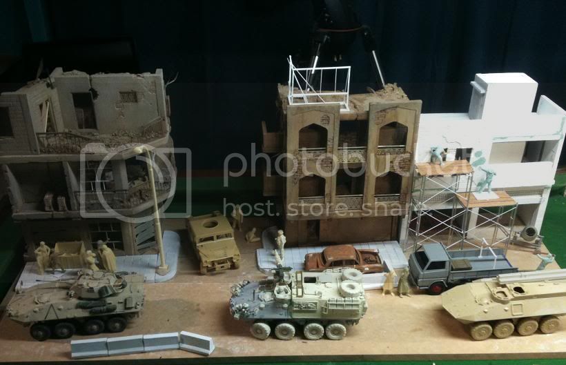
remember i am building for a diorama, and this vehicle forms part of a much larger story, and the figures tie into that in a very important way.
Heres a preview to the diorama layout - remember this is a composition shot only for balance and design validation so not all vehicles are final product etc etc ( I give that caveat because I get asked things like "why is there an american lav in front of an Australian one???" answer - I have'nt built the Aussie one yet) so the last vehicle is representing a fitters..
As for figures- I was looking again at the pc crew from ACM, as I have a spare set for this project. The commander figure and the driver are very "short" and the cupole on this vehicle is quite high. So was thinking about modifying the passenger figure to become the commander and somehow make him handling the mag58. a few chops and changes to the arms, the head can still look to the left, even if the gun and arms are biased to the right. Unfortunately the top doors are molded shut or I would have had a spare digger hanging out with his rifle.
I notice that most drivers in Iraq go hatches down - so the 3 ASLAVs in my dio will not show any of the driver figures.
the body armor of the Aussies seems to be the stumbling block to usung generic modern vehicle crews. Ours is somewhat unique. I havemt researched figures completely but I know I'm stuck with the heads and torsos form ACM, but arms and hands can be changed.
remember i am building for a diorama, and this vehicle forms part of a much larger story, and the figures tie into that in a very important way.
Heres a preview to the diorama layout - remember this is a composition shot only for balance and design validation so not all vehicles are final product etc etc ( I give that caveat because I get asked things like "why is there an american lav in front of an Australian one???" answer - I have'nt built the Aussie one yet) so the last vehicle is representing a fitters..
jasmils
Joined: December 23, 2003
KitMaker: 1,016 posts
Armorama: 745 posts
Posted: Tuesday, December 28, 2010 - 03:14 AM UTC
Quoted Text
Drivers Windshield basket
What a beautiful piece of resin casting this is. A Joy to behold. If only All bustle racks could be like this.
Why, thank you Adam. I was quite surprised with it as well.
Quoted Text
The sprue carrying the basket and the mounting lugs has numbers cast on it - pay no attention to these as they do not match the instructions. It confused me for a minute or two but I used the numbers from the parts list in front of instructions to identify parts and that is consistent with the instruction steps. Also odd that there is no part CN - 3, and 2 parts CN - 2, even though parts CN -2 have a different angle at the bend.]
OHHH. I will have to have a look at that.
Quoted Text
As for figures- I was looking again at the pc crew from ACM, as I have a spare set for this project. The commander figure and the driver are very "short" and the cupole on this vehicle is quite high. So was thinking about modifying the passenger figure to become the commander and somehow make him handling the mag58. a few chops and changes to the arms, the head can still look to the left, even if the gun and arms are biased to the right.
Hold off on it for a bit. I have one on the bench. Also with that, see below.
Quoted Text
I notice that most drivers in Iraq go hatches down - so the 3 ASLAVs in my dio will not show any of the driver figures.
And the rest of the crew is NEVER above the top of the hull/hatches any higher than the middle of the rib cage when on patrol.
Cheers Jason
Adamskii
Joined: November 06, 2010
KitMaker: 537 posts
Armorama: 474 posts
Posted: Wednesday, December 29, 2010 - 12:37 AM UTC
The not so exciting bits.
The following pics show developement of left and right hand side of the rear superstructure. Tool rack on the right hand side is a very tight fit to get all the tools on- I found the secret to fit is to place tools in the right sequence . first the pick handle, then the axe, then the mattock head, and lastly the shovel - the shovel may need some trimming to fit. My shovel needs more trimming.

The right side jerry can holder and brush guard assemble easily. the hardest part is cutting the jerry rack from its carrier, the parts are very delicate, and fitting the water jerries or fuel jerries requires some test fitting. ( I had to shave one Jerry down a very small amount on each side to get a good fit)

Right side jerry rack is same as left - carefull cutting from the riser. The towing frame is very nice , and is completely workable, so if you wanted to use it in an action setting it would work very well. I screwed up the bracket with a wingnut that holds it on - I confused it with the one used to hold the winching block, both were broken away from the sprue/riser when I got the kit. I will explain more next pic.

The winching block bracket has a small extra plate that forms a cross and sits over the blocks main plate. I confused FE5 with CV6. Be carefull when applying these parts!

The rear of the hull.
A few notes here on parts and their labels. I suggest if you do not have the instructions on PDF you email Jasmils (armorama member) or contact Arms Corps Models and request them! The printed version I received with the kit has some errors.
Firstly the image 7 and 8 in both print and PDF show the 3 handles to be added as part TD15. There is only 1 part TD15 in the trumpeter box, the other 2 handles can be found on sprue B parts 41.

The next issue is image 8 shows part CZ3 being used twice, and again used once in image 7. there is only one of these parts of course. easy fix though. one of the CZ3 labels points to the prop guard - disregard this one. replace either of the remaining 2 CZ3 parts with part CZ4 (its identical to CZ3).
Anyways, when CZ1, CZ2, CZ3, CZ4 are in place, I noted I could insert a 1mm rod through the holes on each - they all line up! Just letting you know in case not sure about actual position of the parts. (bit of useless trivia that)

The last pic I have is of the rear completed.

That it for today I think. I have the crane assembly to do next and aparently its a bit of a challenge to line it all up.. so a big blog entry coming I think. Then the headlights, props and brush guards, and thats pretty much it!!! light at the end of the tunnel
The following pics show developement of left and right hand side of the rear superstructure. Tool rack on the right hand side is a very tight fit to get all the tools on- I found the secret to fit is to place tools in the right sequence . first the pick handle, then the axe, then the mattock head, and lastly the shovel - the shovel may need some trimming to fit. My shovel needs more trimming.
The right side jerry can holder and brush guard assemble easily. the hardest part is cutting the jerry rack from its carrier, the parts are very delicate, and fitting the water jerries or fuel jerries requires some test fitting. ( I had to shave one Jerry down a very small amount on each side to get a good fit)
Right side jerry rack is same as left - carefull cutting from the riser. The towing frame is very nice , and is completely workable, so if you wanted to use it in an action setting it would work very well. I screwed up the bracket with a wingnut that holds it on - I confused it with the one used to hold the winching block, both were broken away from the sprue/riser when I got the kit. I will explain more next pic.
The winching block bracket has a small extra plate that forms a cross and sits over the blocks main plate. I confused FE5 with CV6. Be carefull when applying these parts!
The rear of the hull.
A few notes here on parts and their labels. I suggest if you do not have the instructions on PDF you email Jasmils (armorama member) or contact Arms Corps Models and request them! The printed version I received with the kit has some errors.
Firstly the image 7 and 8 in both print and PDF show the 3 handles to be added as part TD15. There is only 1 part TD15 in the trumpeter box, the other 2 handles can be found on sprue B parts 41.
The next issue is image 8 shows part CZ3 being used twice, and again used once in image 7. there is only one of these parts of course. easy fix though. one of the CZ3 labels points to the prop guard - disregard this one. replace either of the remaining 2 CZ3 parts with part CZ4 (its identical to CZ3).
Anyways, when CZ1, CZ2, CZ3, CZ4 are in place, I noted I could insert a 1mm rod through the holes on each - they all line up! Just letting you know in case not sure about actual position of the parts. (bit of useless trivia that)
The last pic I have is of the rear completed.
That it for today I think. I have the crane assembly to do next and aparently its a bit of a challenge to line it all up.. so a big blog entry coming I think. Then the headlights, props and brush guards, and thats pretty much it!!! light at the end of the tunnel
 |

WEB HOSTING BY


Copyright ©2021 Armorama and Kitmaker Network, a subsidiary of Silver Star Enterprises
All Rights Reserved. Please read our Conditions of Use and Privacy Policy.
All Rights Reserved. Please read our Conditions of Use and Privacy Policy.