


Im back with a new update. I recently acquired a copy of Achtung Panzer No. 5 Stug III, Stug IV & sIG 33. A must have reference, if you happen to like all things Stug, that covers in explicate detail all of these vehicles well. I also managed to find a few walk around photographs online of the vehicle at the Kubinka Museum in Russia and quite a number of scans of some of the other vehicles in action during that time period that proved to be most interesting! What I now know is that the vehicle at the museum is built from a Stug III Ausf. E or F chassis. From the photographs that I have acquired, either online or from the above-mentioned book, these vehicles without a doubt were manufactured using Stug III Ausf. B, C, D, E and F chassis, not just ausf. E or F chassis as stated in some publications the photographs tell the story best! The kit just happens to contain almost all of the necessary parts, less the older rear idler wheels, for the modeler to render his or her sIG.33, to any one of the above mentioned Stug III Ausf. chassis configurations right out of the box. Unfortunately the instructions fall way short of this and will only guide the modeler to building one of the early production Stug III Ausf. B, C or D / sIG.33 vehicles. This now just happens to be the chassis type for which my vehicle is based on at this point in the build. So here is where I am now.

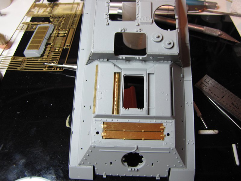
Yes, this is what happens when you go and try to put together a Dragon kit with their famous assembly instructions! There is a separate amendment to steps 7 & 8 that will have you remove the entire shaft portion of the fender support braces (A54, A55 & A56) before installing them to the fenders. This is done to allow the casemate to be installed on the fenders without interfering with these shafts. However on the real vehicle the fender support brace shafts were cut down just enough to allow the casemate to seat flat against the fenders.
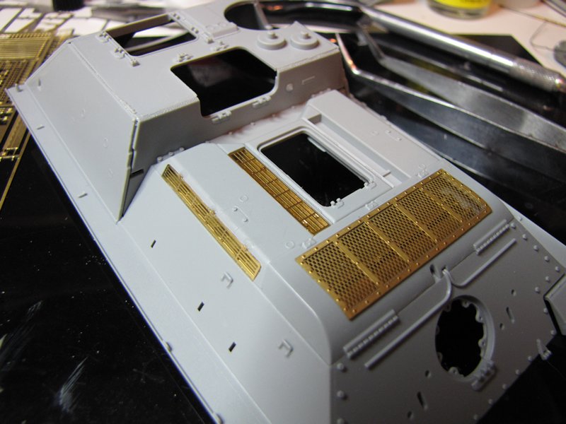
Im just guessing here but It appears that the original intent was to have small square notches cut out on the lower edges of the casemate armor side plates to allow clearance for the fender support brace shafts and perhaps during the actual assembly process the shaft portion of the fender support braces were shortened to fit within the casemate and the notches on the side armor panels welded over with thin pieces of armor plating? (All of which I have indicated with red arrows and the blue dotted cut line). The forward fender support braces (A56) would have needed to be moved, due to the casemates forward armor plate now residing over the same location (red circle) on the fenders, and may have been the same pieces (T25 & T26) now reworked, relocated and welded to the transmission inspection armor plate? Just as a note there is only one fender support brace (A54) and I installed that piece on the left side of the hull, the amendment calls out for two of these pieces to be used but only one of these parts is provided in the kit and the instructions should have called out the other part as A55, which I installed on the right side of the hull (indicated in the photograph).
The same assembly steps will also have you install two PE air intake to fender covers (MA3 & MA4) but nothing letting the modeler know to bend the triangle ends of these parts (red arrows on inset photograph). These parts should fit snuggly against the air intakes (A29 & A30 both intakes are to be installed later in the build).

The PE fender support brace plates (MA18) that sit below the fender support braces (T25 & T26) are called out wrong on the instruction sheet. I added a weld seam around both of the forward relocated fender support braces and an electrical conduit gland support for the Bosh lamp using different diameters of styrene rod (red arrows). A small piece of brass rod was used to replicate the Bosh lamps electrical conduit (not all of these vehicles used this type of lamp or the electrical conduit leading to the lamp).
Both headlamp support brackets, bolted to each towing eye were drilled out with a micro drill (red arrow on inset photograph). As a note: there is also a small hole located just below the rear bottom edge on each of the towing eyes that should be there. At first I thought that these small holes might have been a molding error until I looked at my reference book. These holes were for the electrical cables that were used to power on the headlamps on the Stug IIIs, the headlamps were deleted when the chassis were used for the sIG.33 conversion (not all of these vehicles retained the headlamp brackets on the towing eyes after the conversion). The final inset photograph is just to show how the hinged front fender PE splashguards (MA5 & MA6) reside in their location (a mirror image of the other sides splashguard) on the bottom side of the fenders. The instructions dont call out part of the fenders inside plates (B19 & B20) but one of these pieces is shown on the amendment sheet for steps 7 and 8.

I ran into a bit of a scuffle with the towing eye parts being marked wrong on the assembly instructions so here is the corrected parts call out.

Here Ive added a slight amount of Mr. Surfacer to the final drive housing to replicate a light cast texture. Also added are a pair of Verlinden Productions cast resin bolts to represent the oil drain plugs (I dont know if this would be correct or if these housing had provisions to drain the oil, but it looks good to me!). I left off both bracket sections (A21 & A23) of the forward fender support braces and drilled out holes where the bolts would be to secure these pieces (inset photographs the bracket sections of the forward fender support braces were not always cut away and removed during the conversion). I installed a small piece of styrene to represent a left over section of fender support brace.

OK, I just had to have these four small conical bolts on each of the hulls side armor plates on my kit! I dont know what these conical bolts are there for on these vehicles but they are there on many of the Stug III photographs that Ive seen so I had to have them on my build. I placed them according to a H. L.Doyle 35th scale drawing of the sIG.33. I drilled out the bump stops on the bottom side were they were affixed to their support bracket (just something to do while watching a movie and building).

Used styrene rod to represent the weld seams on the rear towing eyes, these are sometimes almost invisible in photographs but do show up well on current museum walk around photographs. Beside my kits example left me with some observable gaps between the parts after mating them together so I just had to go for it!

I placed a strip of styrene (red arrow) across the front of where the casemate and chassis mate up just to hide a bunch of recessed layers of plastic and the casemates rather large locating tab. I also added thin pieces of styrene to the flooring to hide the mold release depressions. This stuff is not at all accurate but I just didnt want to spend more time filling and sanding so I took the lazy way out! Besides its going to be very difficult to see any of this through the small crew hatch openings. I also filled the gaps between the fenders and hull; the super glue becomes transparent after sanding so the gaps show up in the photograph. On a side note Dragon has done a fantastic job on not having any mold release tool marks of any kind on any of the appearance side of the kits parts!
More coming soon! But for now I am going to go watch something no not porno but some WWII documentaries!
@WARDUKWNZ Phill, thanks for directing me over the US Halftracks Campaign, your PE work looks great. You might consider leaving it naked and sealing it with some clear finish, it would be a shame to cover all of that work with paint. BTW is there a plastic kit beneath the entire PE?
@Tojo72 Anthony, youre moving right along on your SU100. Its already premiered and ready for a coat of some OB1-kanobie 4BO green paint. Clean build and nice job on the dented front hinged fenders did the kit parts come this way?
@Dragon164 Rob, are you getting any sleep? You are highly motivated, gotta love that plastic stuff!
@airborne1 Michael, join in on the fun if you can. There are 62 enlisted participants already and the campaign wont end until December, the more participants the more fun.
@SHAKY962 Jose, thanks for the kudos, it is much appreciated. Hope my build information will be of some use to you when you go and get this kit in your hands and build it. Although only 24 of these SPG's were built, except for the basic encasement's shape, they are not all alike. And because only a handful of photographs have ever surfaced your able to use a little artistic license, within reason, to personalize your build and no one can say that its wrong! Just do your research where it concerns the Stug III chassis (Ausf. B, C, D, E or F) of your choosing. All of the parts are in the kit to accommodate any one of these chassis types. As I had mentioned on my last update it would have been nice to have had the early Ausf. A rear idler wheels in the kit too!
@Nito74 John, youre also moving right along on your build, I see you have added the extra wiring for the lighting system and horn on the fenders, nice. I like your wood flooring. And now youve managed some paint on the running gear and interior parts too!
@1721Lancers Paul, you already have a coat of paint on your build and have detail painted some of your stuff too. Man, youre working that baby! Paul, I actually havent decided on the paint scheme for my build yet. But Im leaning towards the Dark Yellow and camouflage strips theme . . . what do you think? Should I go with that?
@PantherF Jeff, that Brilliant minds photograph you posted makes me hungry to have a pizza with a cold one every time I see it, and I dont do much drinking. Well I see youre off to a good start on your build.
@jkb_sprint John, now you have double the fun on your workbench and some spare parts from your other Jagdpanzer IV, just in case you need something that may get eaten by the carpet monster. Good to see you doing some progress on both your builds.
@Cannon99 Karl, that looks like a nice kit. Both you and John are building a similar project. Ive always liked this little SPG, I remember having the 72nd ESCI kit when I was young and it was my favorite.
~ Eddy


