Hosted by Darren Baker
Build: PzKpfw.II Ausf.F -- CyberHobby #6263
TMikeCurry
Missouri, United States
Joined: June 02, 2009
KitMaker: 128 posts
Armorama: 97 posts
Joined: June 02, 2009
KitMaker: 128 posts
Armorama: 97 posts
Posted: Tuesday, October 16, 2012 - 04:09 AM UTC
For a little variety while recuperating from that flu bug, I also spent some time working on the transmission. There are these vent openings on part C16 (right) that have a fair job of simulating the look of the perforated metal of the real thing, but I thought I'd drill them out like Steven did on his II-C.
I started with a drill bit that was smaller than the diameter of the vent openings. Drilling from the outside left the rough edge on the inside of the part. I then used a tapered round file from the inside to enlarge the hole to the right diameter. This removed the rough on the inside, kept a cleaner edge on the outside, and let me see the hole growing (watching from the outside) while I worked. Slowly twisting the file, I could apply more pressure one direction or the other to make sure the hole ended up both centered and the right size. Frequently I had to clean the little plastic bits from the file or it gummed up fairly quick.
Part C48 has two oblong openings in it that I can find in photos of the real thing. The Dragon part doesn't have these openings. I drilled two closely spaced holes from the outside with my pin-vise drill. After that I used an x-acto knife to cut through the small "bridge" between the two holes. Then I just worked at it until I had straight edges between the two holes. The last thing I did was cut a thin strip of sand paper, fold it over, and slide it back-n-forth in the straight part of the oblong to smooth out the x-acto knife cut marks. I've still got some more to do to finish getting the edges smoother, but I think it's taking shape pretty good.
One thing I'm not sure of though. I can't tell if the oblong openings have a perforated metal sheet in them, or a solid plate with a bolt (access plate, maybe?) One internet photo I've collected looks like it's a solid plate with a bolt. Another looks like maybe it is a perforated sheet. Could this be one of those II-C vs II-F differences for which I've been trying to watch?
TMikeCurry
Missouri, United States
Joined: June 02, 2009
KitMaker: 128 posts
Armorama: 97 posts
Joined: June 02, 2009
KitMaker: 128 posts
Armorama: 97 posts
Posted: Tuesday, October 16, 2012 - 04:14 AM UTC
Next came an exercise in patience. The Dragon II-F comes with the same solid one-piece gear shift and guard rail part as the Dragon II-C. I decided I too would carve out the extra plastic. It's a small fragile piece, and it gets more fragile as plastic is removed. Frequent swipes across the honing stone kept the x-acto knife removing paper-thin slivers for the better part of the day... in between naps and coughing fits, that is.
I found that making two cuts shaping kind of a curving 'V' worked best. I'd slice down through one side, and then down through the other side so the two curving cuts met at the bottom of the 'V'. The sliver thin vee of plastic would then pop free. After a while I had all these progressively larger tiny vee's of plastic on my work table. A good sneeze took care of them for me though.
Once the removed portion of plastic was wide enough, the two cuts wouldn't meet up anymore. After that I'd gently nip the curved sliver off with the x-acto knife.
When I got to the point where the only excess plastic remaining was between the gear shift arm and the guard rail, I was kinda stuck. There just wasn't enough room, and not enough leverage on the now very fragile part, to do any more x-acto knife cutting.
I have some old speaker wire though. It's the good kind from back in the day of LP records. One side is braided copper and the other is a braided steel-colored metal. I stripped out one strand of the braided steel-colored metal and strung it between the outstretched arms of my little multi-armed clip stand. Then I borrowed one of my wife's little scented candles, set it beneath the strand, and lit it. Very shortly the wire strand heated up enough that it parted the plastic quite easily.
After that I was able to do a little more on the (now) two parts with the x-acto knife. The final work was a lot of very gentle sanding with a fine sanding stick to remove the last of the excess plastic, as well as smooth and even the surfaces. (The photo above I took a bit before I was done.)
TMikeCurry
Missouri, United States
Joined: June 02, 2009
KitMaker: 128 posts
Armorama: 97 posts
Joined: June 02, 2009
KitMaker: 128 posts
Armorama: 97 posts
Posted: Tuesday, October 16, 2012 - 04:15 AM UTC
Okay, I splurged and didn't tell anybody. It arrived in the mail while I was down with the worst of the flu. RB Model # 35B25. I actually forgot about it until my wife reminded me she'd left it on the dresser for me. Looking at them side-by-side, the metal barrel looks to be a little smaller in diameter than the Dragon plastic barrel. Good grief, I have no idea how I'm going to get those tiny little bolt heads into place. Maybe the tape trick will work again??
Well, I've posted a lot here all at once, but it's what I got done while getting better from that flu. I don't normally have so much time all at once like that to work on modeling. Usually it's ten minutes here, twenty there.
TMikeCurry
Missouri, United States
Joined: June 02, 2009
KitMaker: 128 posts
Armorama: 97 posts
Joined: June 02, 2009
KitMaker: 128 posts
Armorama: 97 posts
Posted: Tuesday, October 16, 2012 - 06:21 AM UTC
The photo above is how I glued the guard rail in place without gluing my fingers to the parts. Thank goodness for my bottle of CA glue with the little brush applicator in the cap. With the parts in position, all I had to do was touch the join and the glue flowed in. I don't see any way I could have applied the glue and held the part in place with my fingers and not have made a big mess of it all.
TMikeCurry
Missouri, United States
Joined: June 02, 2009
KitMaker: 128 posts
Armorama: 97 posts
Joined: June 02, 2009
KitMaker: 128 posts
Armorama: 97 posts
Posted: Wednesday, October 24, 2012 - 04:03 AM UTC
Got a little more work done. Made the clutch lever out of plastic sheet and added a piano wire handle, plus dug out that PE sheet of hex nut heads I got at the model show last year. The success with the little plastic nuts on the drive housing gave me the courage to try an even tinier hex nut head. I now have a new record for the tiniest part I've ever worked with!
Also did some significant reshaping of those gosh-awful parts that connect to the drum wheels in the front.
I still haven't come up with a way to simulate the mesh inside the air vents for the transmission. Poking spaced holes in a sheet of paper with a needle didn't work out well. Not sure what I'll try next. Maybe I'll just wait until payday and find some PE mesh on Ebay to order.
A little more work on the floor.
SDavies
England - South East, United Kingdom
Joined: January 09, 2010
KitMaker: 979 posts
Armorama: 959 posts
Joined: January 09, 2010
KitMaker: 979 posts
Armorama: 959 posts
Posted: Wednesday, October 24, 2012 - 05:08 AM UTC
Very nice work so far on your Panzer 2 and it going to be impressive when completed
S
S
Plasticat
Idaho, United States
Joined: September 03, 2003
KitMaker: 448 posts
Armorama: 245 posts
Joined: September 03, 2003
KitMaker: 448 posts
Armorama: 245 posts
Posted: Wednesday, October 24, 2012 - 06:26 AM UTC
Hey Mike,
Looking good so far!
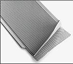
For small mesh I have a piece of shielded ribbon cable, like you find in some computers that has just the ticket. The shielding in these cables is a really fine copper mesh that works great for models. I can't remember where I acquired this cable, I think it was an old discarded computer....
TMikeCurry
Missouri, United States
Joined: June 02, 2009
KitMaker: 128 posts
Armorama: 97 posts
Joined: June 02, 2009
KitMaker: 128 posts
Armorama: 97 posts
Posted: Wednesday, October 24, 2012 - 10:43 AM UTC
Thanks Steven and Leroy. I appreciate the replies!
I have some old (ancient) computers at home with the ribbon cable... I think I'll open one up and see if I have some of that shielded kind with the mesh. Great tip. Thanks!
AFVFan
North Carolina, United States
Joined: May 17, 2012
KitMaker: 1,980 posts
Armorama: 1,571 posts
Joined: May 17, 2012
KitMaker: 1,980 posts
Armorama: 1,571 posts
Posted: Wednesday, October 24, 2012 - 11:37 AM UTC
Looking good, so far. I skimmed over some of your longer posts so if I missed you buying a file set already forgive this.
While Micro-mark does carry a higher quality tool, you do pay for them. I would suggest a set off Ebay. Just look up "mini files" or "jewelers files" and you should come up with plenty to choose from that will work quite well with the plastic and brass of model kits. On a side note, the same thing goes if you need a set of mini drill bits.
BBD468
Texas, United States
Joined: March 08, 2010
KitMaker: 2,465 posts
Armorama: 2,383 posts
Joined: March 08, 2010
KitMaker: 2,465 posts
Armorama: 2,383 posts
Posted: Wednesday, October 24, 2012 - 01:28 PM UTC
Very nice build indeed! Lookin' good Mike.
Gary
Gary
robw_uk
England - North East, United Kingdom
Joined: June 22, 2010
KitMaker: 1,224 posts
Armorama: 1,207 posts
Joined: June 22, 2010
KitMaker: 1,224 posts
Armorama: 1,207 posts
Posted: Wednesday, October 24, 2012 - 10:14 PM UTC
Quoted Text
Okay, I splurged and didn't tell anybody. It arrived in the mail while I was down with the worst of the flu. RB Model # 35B25. I actually forgot about it until my wife reminded me she'd left it on the dresser for me. Looking at them side-by-side, the metal barrel looks to be a little smaller in diameter than the Dragon plastic barrel. Good grief, I have no idea how I'm going to get those tiny little bolt heads into place. Maybe the tape trick will work again??
Well, I've posted a lot here all at once, but it's what I got done while getting better from that flu. I don't normally have so much time all at once like that to work on modeling. Usually it's ten minutes here, twenty there.
i used the same barrel on my PzII - didnt know what the "extra" flat piece was so didnt use it... (having no instruction is the only downsize for these additions)....
love the work you are doing on this - its a far more comprehensive kit than the Tamiya one....
TMikeCurry
Missouri, United States
Joined: June 02, 2009
KitMaker: 128 posts
Armorama: 97 posts
Joined: June 02, 2009
KitMaker: 128 posts
Armorama: 97 posts
Posted: Thursday, October 25, 2012 - 11:22 AM UTC
Bummer, no luck yet on an old computer ribbon cable with a copper mesh in it. I have a few more to check out though.
Thanks for the encouragement Gary and Bob. It makes me more eager to get home and do some more work on the Panzer-II when I read these at the end of the work day.
I looked at Micro-Marks web site and drooled on myself for all the things I'd love to order! Oh, oh, how much longer until payday?!? I took a look on ebay like you suggested and yes, there's some good looking sets to check into there. "Lapidary Jeweler" and "Watchmaker Jeweler" seem to be the best search terms to use. Thanks! But payday seems so far away now...
Robert, thank you also!
The little flat piece is supposed to be the head of a bolt and a small under-plate. On the 1:1 tank this held the flash suppressor in place so it didn't come off (un-screw from?) the end of the barrel. The package has two of them, but I'm pretty sure only one is needed on the barrel.
I assume the second one is for when one sneezes and loses the first one! ;p
My conundrum is does it go on one of the flat spots toward the base of the flash suppressor? Or does it go between the two flat spots. I just need to find a clear picture of the 20mm barrel with its flash suppressor that shows the bolt.
TMikeCurry
Missouri, United States
Joined: June 02, 2009
KitMaker: 128 posts
Armorama: 97 posts
Joined: June 02, 2009
KitMaker: 128 posts
Armorama: 97 posts
Posted: Thursday, October 25, 2012 - 11:39 AM UTC
Found an image of it, but it's not of the 1:1 tank... though I'm going to assume it's accurate.
Hmm. I guess it's supposed to be two bolt heads, actually.
TMikeCurry
Missouri, United States
Joined: June 02, 2009
KitMaker: 128 posts
Armorama: 97 posts
Joined: June 02, 2009
KitMaker: 128 posts
Armorama: 97 posts
Posted: Monday, November 12, 2012 - 05:03 AM UTC
Yeah! Whoo-hooo! At last I have found some decent images of the inside of the forward compartment!
Things inside the real tank were a ~lot~ different than what the model pieces depict. The whole series of linkages, spring, and rods shown above is only abstractly (very abstractly) represented in the model. In the image it looks like somebody cut through the linkage rods; probably to disable this particular tank. Also, I hope that's a sleeve for the axle... otherwise the driver would have had his feet right near a spinning axle. Surely it's a sleeve with the axle inside it. 8-o
TMikeCurry
Missouri, United States
Joined: June 02, 2009
KitMaker: 128 posts
Armorama: 97 posts
Joined: June 02, 2009
KitMaker: 128 posts
Armorama: 97 posts
Posted: Monday, November 12, 2012 - 05:04 AM UTC
I'm getting a much better idea how all the linkages work and what they do. In fairness to Dragon, that's a lot of little stuff that I imagine would be awful hard to reproduce in miniature plastic.
Okay, so clutch pedal on the left, brake pedal on the right. I still have no idea what the center round pedal does. These images, plus the others I have, have helped me tremendously. I'm beginning to see why some military historians I've read commented that German WWII vehicle engineering was often "overly complicated" or "over-designed".
TMikeCurry
Missouri, United States
Joined: June 02, 2009
KitMaker: 128 posts
Armorama: 97 posts
Joined: June 02, 2009
KitMaker: 128 posts
Armorama: 97 posts
Posted: Monday, November 12, 2012 - 05:07 AM UTC
Armed with my trusty images of the interior of a Pz.II ausf-F, I decided I would try my hand at replicating a representation of these linkages and stuff. I measured. I marked. I drilled and I cut. I snipped pieces of piano wire. I carved. I sanded little tiny pieces of flat plastic. Here's what I have so far...
Oh joy! Somewhere I got off on my measurements for the holes for the rods. It wasn't so obvious when I drilled them. It really sticks out when the rods are in place. Aargh. Things just aren't taking shape the way I'd hoped they would. This model is already complicated enough for me and here I am seized with this desire to add all this additional stuff. This is not so easy creating stuff like this... I'm having to figure out what I'm trying to do ~and~ how to do it as I go here. Yee-arrgh!
TMikeCurry
Missouri, United States
Joined: June 02, 2009
KitMaker: 128 posts
Armorama: 97 posts
Joined: June 02, 2009
KitMaker: 128 posts
Armorama: 97 posts
Posted: Monday, November 12, 2012 - 05:14 AM UTC
Please don't ask me how many times I cut and sanded the same little parts. Some broke. Some went flying into the unknown realm, heralded by the "click" of the tweezers as the part slipped out from between the griping arms of the tool.
Still though, this has been a good learning experience. I am certainly learning how to handle tiny little parts! Drilling little holes with the pin vise goes a lot easier if you put the plastic piece on a piece of wood. The drill bit then does not push through the bottom of the plastic and flare out little chunks from the hole.
TMikeCurry
Missouri, United States
Joined: June 02, 2009
KitMaker: 128 posts
Armorama: 97 posts
Joined: June 02, 2009
KitMaker: 128 posts
Armorama: 97 posts
Posted: Monday, November 12, 2012 - 05:19 AM UTC
I am not satisfied with my attempt at fabricating the steering arms out of sheet plastic. The rounded part of the handles looks terrible. I think they look like I stuck two of those little cheap paperbook matches in there. The problem is getting the putty sanded down to a nice round shape with as delicate as the thin plastic is.
And then there's the piano wire rods at odd angles with their holes being off. *grrr*
*sigh* I think it's re-do time.
I'm going to have to figure out how to re-do the rod in front of the drivers seat definitely. On the plus side, after a trip to the hardware store (which surprisingly had some very small brass tubing!) I am feeling better. The driving handles version 2.0 (above) I think are gonna look pretty good! (Or at least much better than the "match sticks").
I used some round-head nuts from a resin detail pack I picked up at that model show last year. There just happened to be one size that fit perfectly on the end of the handles. Every time I tried the little figure-8 sanding pattern the instructions show, I ended up with a rounded bottom. It worked better gripping them with the tweezers and oh-so-gently dragging them back and forth across a piece of fine emery paper. That required a lot of patience... but it worked!
SDavies
England - South East, United Kingdom
Joined: January 09, 2010
KitMaker: 979 posts
Armorama: 959 posts
Joined: January 09, 2010
KitMaker: 979 posts
Armorama: 959 posts
Posted: Monday, November 12, 2012 - 05:30 AM UTC
Good progress, and I like those images that you have of the Panzer 2, I wish I had them when I was building mine.
The center pedal is the accelerator I believe.
If you think that the Panzer 2 is over engineered try building a Tiger
S
The center pedal is the accelerator I believe.
If you think that the Panzer 2 is over engineered try building a Tiger
S
TMikeCurry
Missouri, United States
Joined: June 02, 2009
KitMaker: 128 posts
Armorama: 97 posts
Joined: June 02, 2009
KitMaker: 128 posts
Armorama: 97 posts
Posted: Monday, November 12, 2012 - 11:40 AM UTC
Steven;
Thanks for the encouragement!
I wondered where the accelerator was. Odd though, for some reason I thought the throttle would be more like what you find on a tractor (usually a lever) as opposed to what you'd find in a car (a pedal).
The interior of a Tiger I... oy! I think I'll go run and hide from that until I've got 15 or 20 more models under my belt!
TMikeCurry
Missouri, United States
Joined: June 02, 2009
KitMaker: 128 posts
Armorama: 97 posts
Joined: June 02, 2009
KitMaker: 128 posts
Armorama: 97 posts
Posted: Tuesday, November 13, 2012 - 07:21 AM UTC
Here are the rods or bolts or whatever they are that go between the arms of the brake pads as seen in the reference photos.
TMikeCurry
Missouri, United States
Joined: June 02, 2009
KitMaker: 128 posts
Armorama: 97 posts
Joined: June 02, 2009
KitMaker: 128 posts
Armorama: 97 posts
Posted: Monday, November 19, 2012 - 05:13 AM UTC
The photo-etch mesh I ordered online arrived. Having never cut PE this thin and fragile it was indeed a challenge figuring it out. Real sharp scissors with clean matching edges and no nicks finally worked... errrr... well enough. Something tells me there's a better way to cut this stuff, though.
The mesh was so light and fragile putting it in place was tough. I found licking the end of a toothpick made it a great tool for picking up or moving PE mesh. Getting it to stay in place to glue down was a whole other issue. Bummer, I see I left a gap on one side of the vent.
TMikeCurry
Missouri, United States
Joined: June 02, 2009
KitMaker: 128 posts
Armorama: 97 posts
Joined: June 02, 2009
KitMaker: 128 posts
Armorama: 97 posts
Posted: Monday, November 19, 2012 - 05:14 AM UTC
The brake assemblies, chair, and transmission are just set in place and not glued down yet. The new steering arm is just sitting there also. I think the new arms look much, much better. Beneath it, the position of the clutch rod has been corrected.
Since the middle pedal (above) is the gas (Thanks Steven!), the molded-on plastic rod connecting to it on the front wall needed to be trimmed back to about the mid-point of the transmission. One of the reference photos I have shows what I know now is the accelerator cable coming across the top of the transmission on its path back to the engine.
TMikeCurry
Missouri, United States
Joined: June 02, 2009
KitMaker: 128 posts
Armorama: 97 posts
Joined: June 02, 2009
KitMaker: 128 posts
Armorama: 97 posts
Posted: Monday, November 19, 2012 - 05:16 AM UTC
I don't have a photo showing it, but I figured there had to be something that turned the pedal motion into the draw motion to move the accelerator cable. So, right in front of the middle of the transmission, I created a little box with a three-quarter circle off the side of it. The accelerator cable will connect to the bottom of this. It will then go over the top of the little roller assembly I created on the top front of the transmission.
BBD468
Texas, United States
Joined: March 08, 2010
KitMaker: 2,465 posts
Armorama: 2,383 posts
Joined: March 08, 2010
KitMaker: 2,465 posts
Armorama: 2,383 posts
Posted: Monday, November 19, 2012 - 06:41 AM UTC
Just lovely scratch work Mike. Between you and Steven, there is a wealth of scratch building references. Great work man!
Gary
Gary