@ Dave V.: Hmmm... simple? Well, to paraphrase v. Clausewitz:
"Everything in PE is simple, but the simplest thing is difficult. The difficulties accumulate and end by producing complications that are inconceivable unless one has experienced PE."
Can't beat the classics!
@ Keith: LOL! Thanks, my friend!
@ Jerry: I donno, old buddy... I think sometimes you just have to climb mountains because they're there, and some modeling projects just have to be done for the challenge. I think these Voyager PE assemblies fall into that category - a challenge just for the fun of it.
@ David: Glad you're finding the build inspirational. The AFV Club Churchill kits are really first class.
I have to say that there's one guy in the world that I know doesn't get paid enough - the guy who builds the Voyager PE sets for their box top photos.
So, here's to you, Mr. Voyager PE-Building guy! You deserve a cold, frosty adult beverage AND a pay raise!

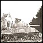
Moving right along with the Churchill fenders, after the front fender flaps (hoods?), the forward third of each fender is next.
Here's where Voyager has let us down - The instructions are, well, let's just say, the instructions leave a lot to be desired. There should be a lot more detail, and frankly, I think the hinged rear portions of the front fender flaps should have been included with the main fender construction and not with the flaps.
In order to fit my flaps to the front edge of the main fender, I had to CAREFULLY flatten and re-bend these parts. Re-bending PE is just asking for disaster - i.e. broken PE parts. I managed to do this, but I was worried the whole time that the bends would break.
I would suggest to anyone building these Voyager Churchill fenders in the future that you construct the front thirds of the main fenders and then bend these parts to conform to the profile of the main fenders. You'll still need the front fender flaps to check the main fenders against, but the hinge parts should be made with the main fenders and not with the flaps. It's a sequencing issue that's important to getting good fit and finish.
Part of the problem that I'm having with these instructions is that the ones included in my set are B&W photocopies and not the usual sharply printed, color-coded instructions. This is not the first set of Voyager PE that I've received with photocopied instructions, but in this case, the copies are difficult to read (as well as lacking detail).
Anyways, the photos tell the tale...


At this point, I think that the PE fenders also have to be fitted to the model hull. Adjustments and alterations can be made at this stage without breaking off details, etc. Lots of handling involved, which is why I'm building the fenders now.


In the photo above, the rivet heads across the heavy vertical plate are actually punched from heavy foil sheet. Voyager would have the builder emboss these rivet heads, but I thought it would be faster and impart less distortion in the PE part to add these as appliqués rather than do the embossing. The foil rivet heads are attached with acrylic matt medium.


One thing that Voyager does do that's very nice is that most of the bolt heads you can see on these assemblies are actually etched as little "tabs" along the edge of the PE parts. These are folded over and create a "double thickness" detail that "self positions." Once folded over, these are simplicity in itself to solder in place. Once soldered, during final clean up of the subassembly, the little "rump" edges of the tabs can be sanded off leaving the soldered on bolt heads.
A very neat design that speeds up construction over soldering on each bolt head individually.
Anyways, happy modeling!


 Always looking forward to the next update.