So, what exactly was the MBT/Kpz 70? Theres a great Wikipedia entry on the subject, but essentially this joint US-West German project from the 60s was aimed at creating a new generation of main battle tanks to replace the excellent Leopard 1 and M60 in frontline service against the expected Soviet assault across the East European plains. The Leopard was a fine tank, but its armour wasnt thick enough to survive the latest AT weapons, while its main gun (the Rheinmetall version of the British L7 105mm) was becoming outclassed. And the M60, with its prodigious thirst and extreme height had its own problems.
The new project would be more powerful, faster, harder-hitting, and better protected than these existing MBTs. However, as everyone knows, a horse designed by committee often winds up looking like a camel! Competing interests saw the tank fitted out with almost every gadget imaginable, with inevitable effects on performance and cost. As a result, the intended weight-class of about 45 tons soon ballooned almost as much as the budget, and eventually the Germans pulled out and used the lessons learned to develop the rather nifty Leopard 2. The Americans also cancelled the project a couple years later, developing the M1 Abrams instead.
Advanced features included adjustable-height hydra-pneumatic suspension that could drop the tank for a low hull-down stance, or tip it for a level platform on the backslope of a hill. Then there was the radical idea of housing all three crew in the turret to make the hull even lower this placed the driver in a rotating cage so he always faced the hull front regardless of how the turret was traversed! (He could also swing to the rear for high-speed getaways ) And the crew was only three because the main gun had an autoloader. Then there was the 20mm cannon in a pod on the turret side, used for anti-aircraft defence as well as targeting soft-skins on the ground. This gun popped up from its armoured covers like something out of Thunderbirds!
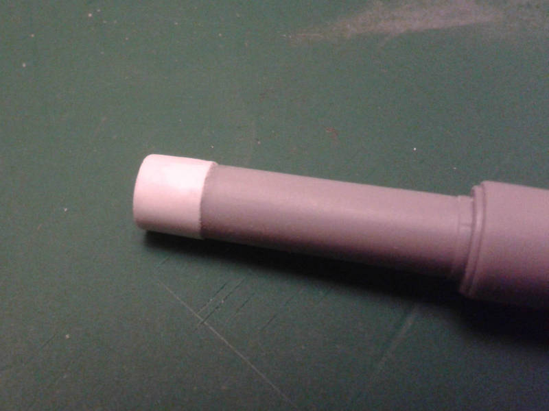
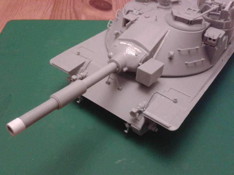
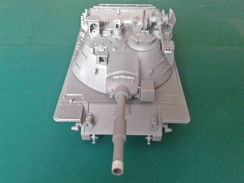
The Achilles Heal of the project was the main gun, the US XM-150 152mm smoothbore dual-function tube for either the Shillelagh missile or a conventional projectile. Essentially a larger version of the gun in the M551 Sheridan and M60A2 starship, it suffered the same range of problems.
Just over a dozen tanks were built by the US and West Germany, with a number of differences in things like powerplants, so the surviving tanks are as unique as snowflakes. The DML kit represents the German version, based on the vehicle currently in the Munster museum. (The one in Koblenz has a different engine deck.) Builders wanting a US version will have to carry out some surgery, or wait for the AM guys to fill the gap.
There are some walkarounds out there, including this Armour Workshop one at Munster, a PrimePortal one of the Munster tank, a mixed-bag of mostly Koblenz shots, and the Armour Workshop study of the Koblenz vehicle. For the truly scratch-happy there are also walkarounds of the American versions, such as Matt Flegals shots at Fort Knox.
THE KIT
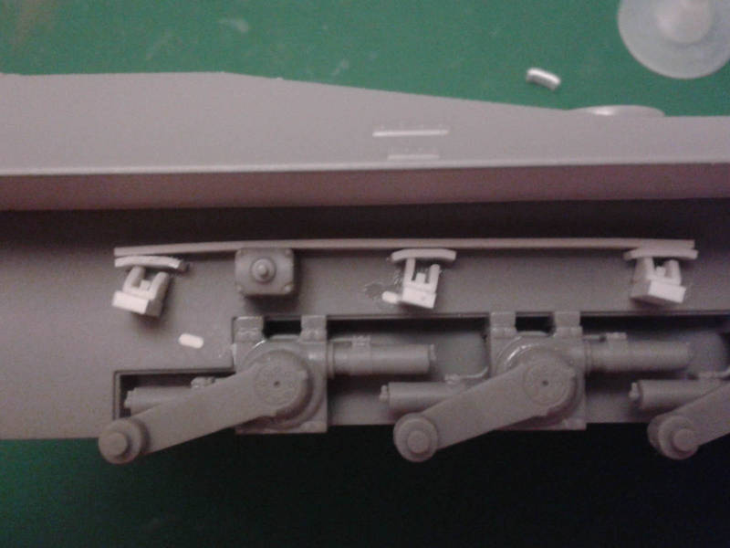
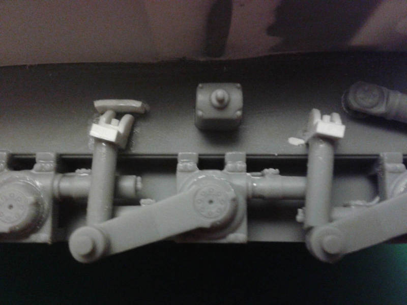
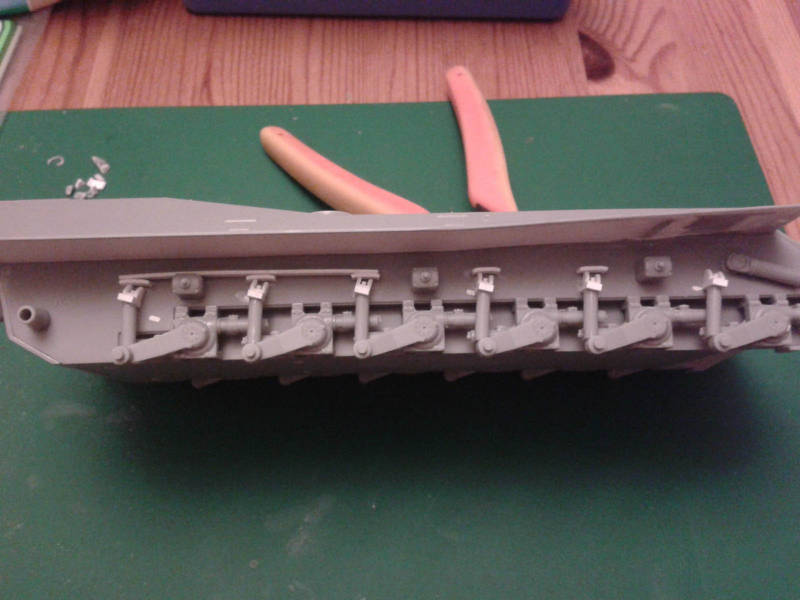
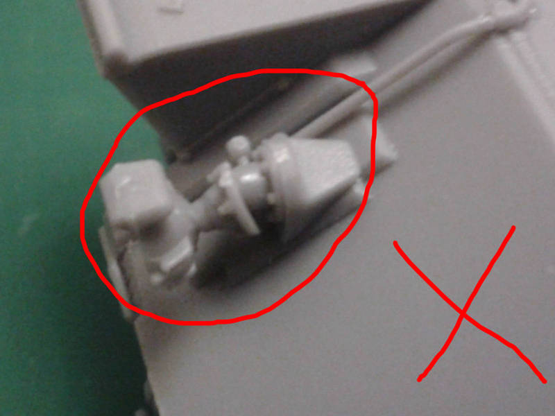
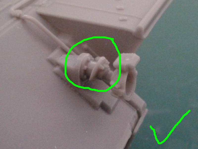
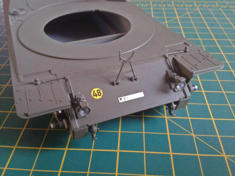
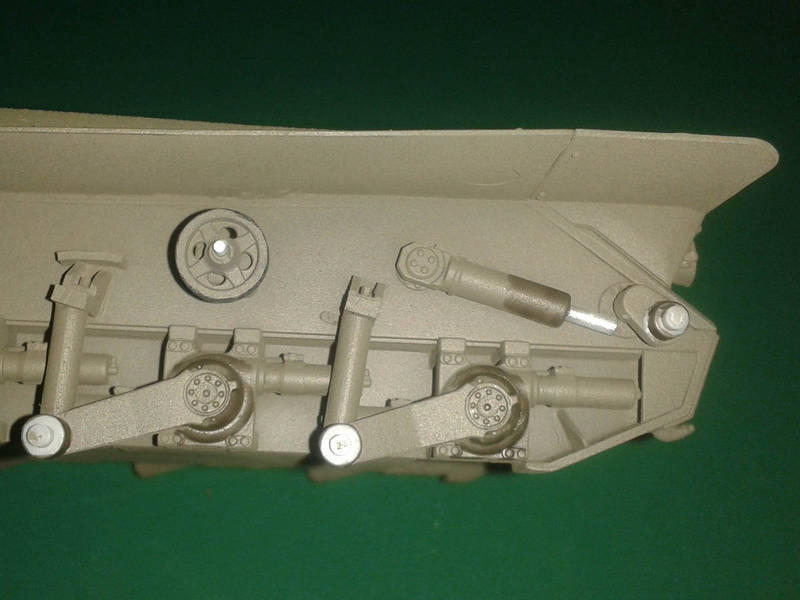
Jim S gave a video preview that included all the sprue shots, so Ill just jump in with the build. Looking things over, this kit is indeed very close to the Munster prototype which is great considering the concerns voiced in the run-up to its release. The one obvious flaw is an odd one the bump-stops for the suspension arms are the Koblenz-style snubbers rather than the Munster shock-absorber types, and this is unfortunately visible from the side. What makes it odd is DML included a four-page photo-essay of the real tank to prove the accuracy of their model, and the correct bump-stops are clearly visible in the pictures go figure!
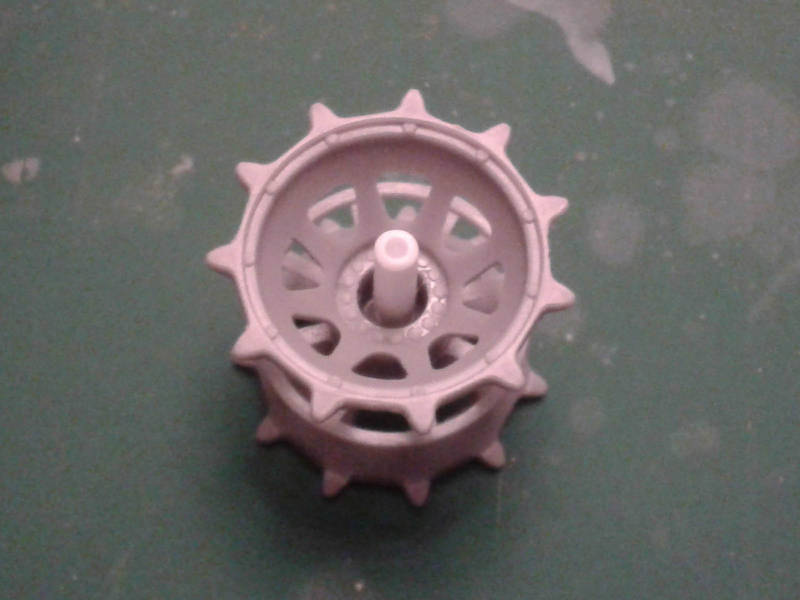
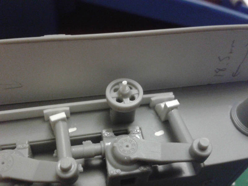
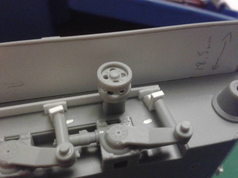
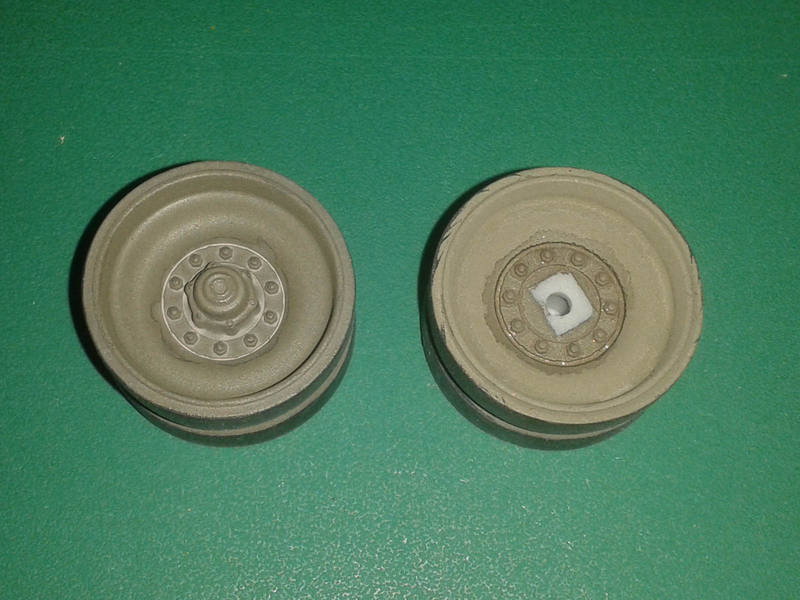
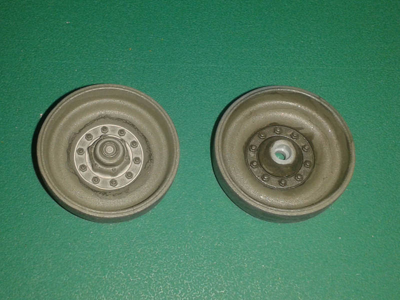
The hull matches the few basic dimensions I have on the vehicle, to within the tolerance of my Mk.1 Eyeball and ruler. One thing to note is the odd assembly sequence that invites you to add lots of delicate detail before joining the hull top & bottom together I will be gluing the main lumps together before adding anything breakable! Also, the lower hull tub on my sample is warped inwards at the top, so I need to fit a series of braces to push it out or the sponson fillers wont meet the edges of the upper hull. The other odd thing is the suggestion that the wheels be glued to the suspension arms before fitting them to the hull again, I will follow a more traditional assembly sequence and fit the arms to the hull first. (I like to leave wheels loose for painting )
One nice touch is the set of instructions for lowering the suspension, in case you want yours to tilt or squat. Bear in mind this will affect track tension
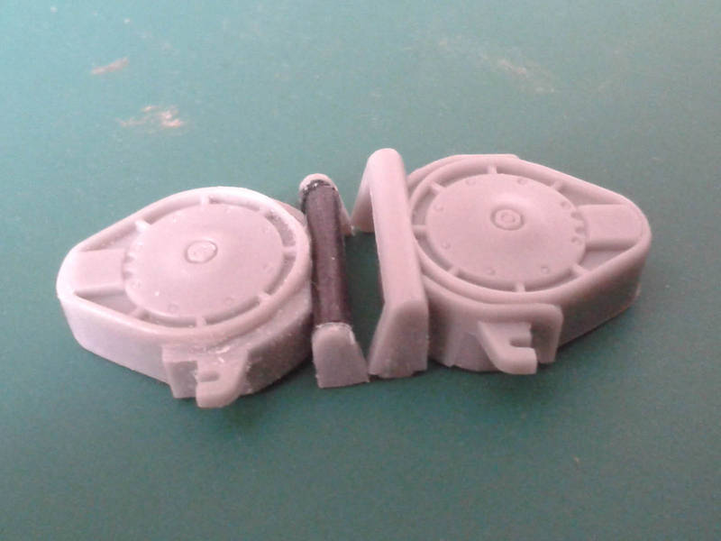
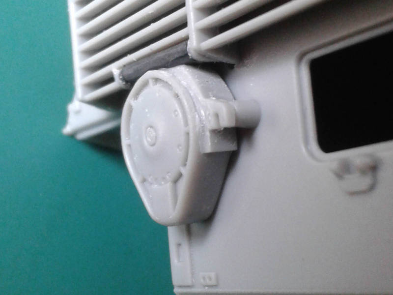
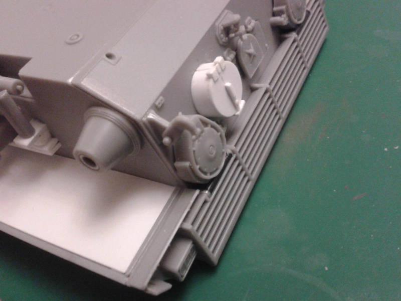
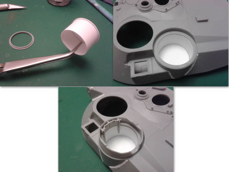
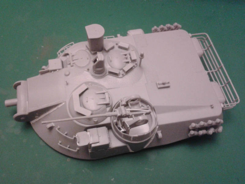
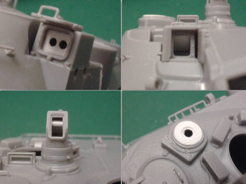
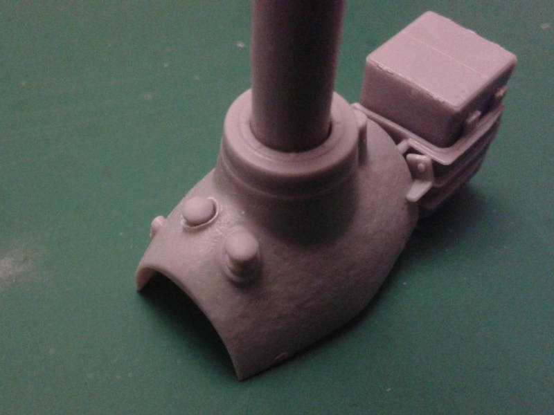
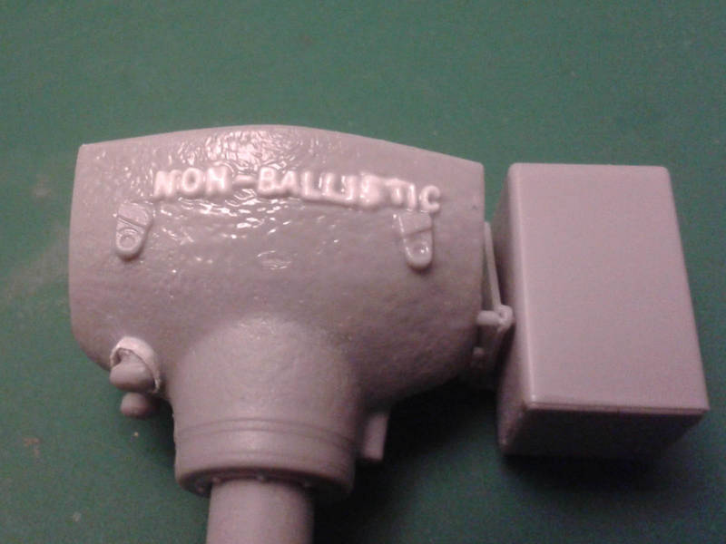
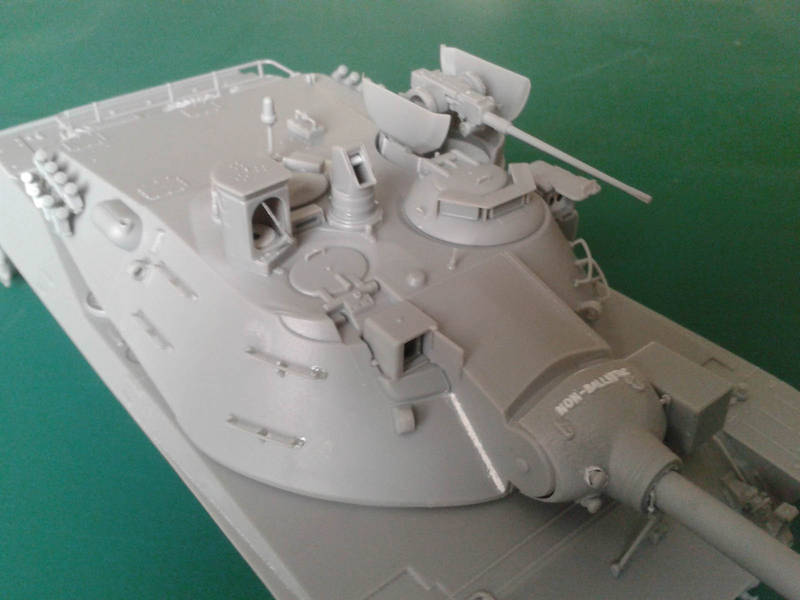
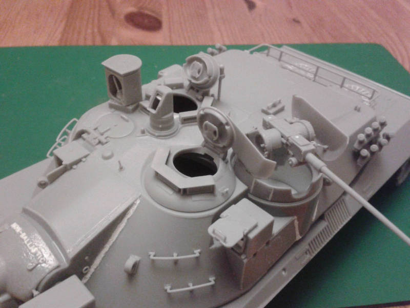
Up on that big turret, the hatches for the commander and driver are separate parts, but the gunners hatch is moulded closed why? The drivers hatch sits in a ring that rotates on the real thing, so at least you can position it to face hull-forward. In front of the commanders hatch is a large boxy sighting device that can pivot for targeting, and is retractable. DML offers instructions to show how to pivot it (by cutting off a part of the fixed base that is inexplicably moulded onto the sight box), but as the retractable base is moulded onto the turret you cannot retract the device without a little surgery. In front of the gunner is his sight, with glass and a door that can be posed open or closed. A separate transmitter for the missile sits in a box in front of the 20mm cannon, again with glass and a closable door. Sadly, none of these devices have any of the optics behind the glass, which is visible in photos of the real things.
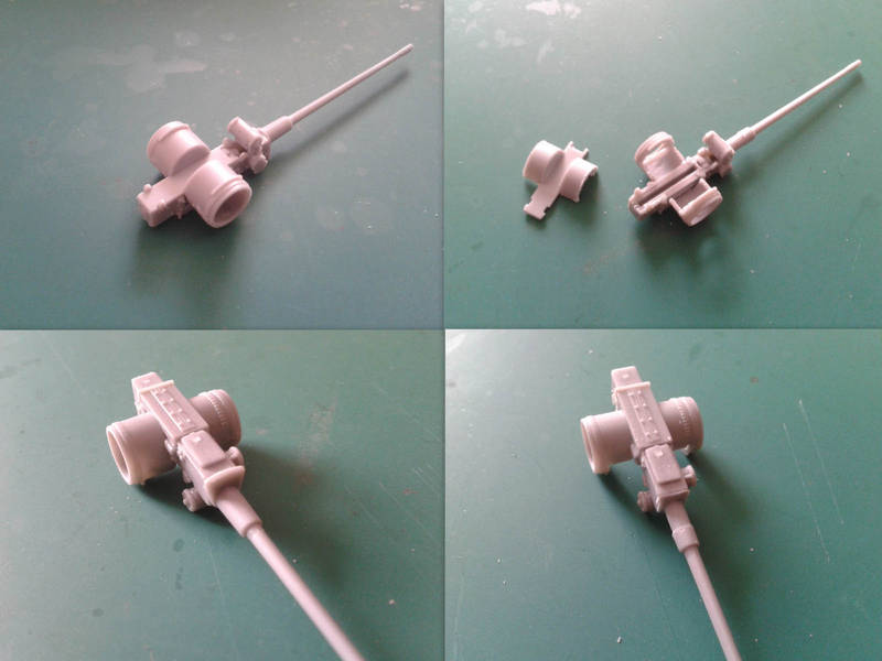
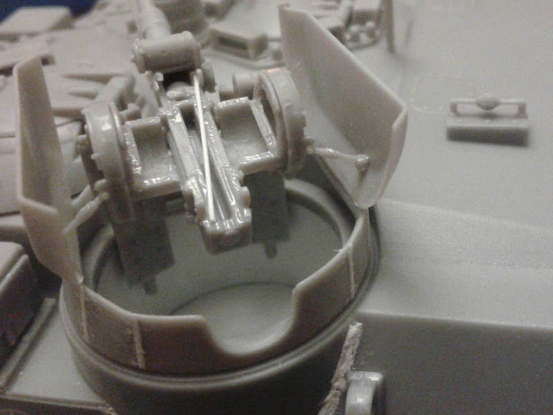
The 20mm gun is a kit in its own right, with options to build it lowered for storage or raised for action. With careful construction it can elevate, and the whole assembly can be left loose to traverse.
PART 1
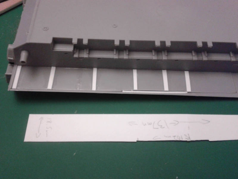
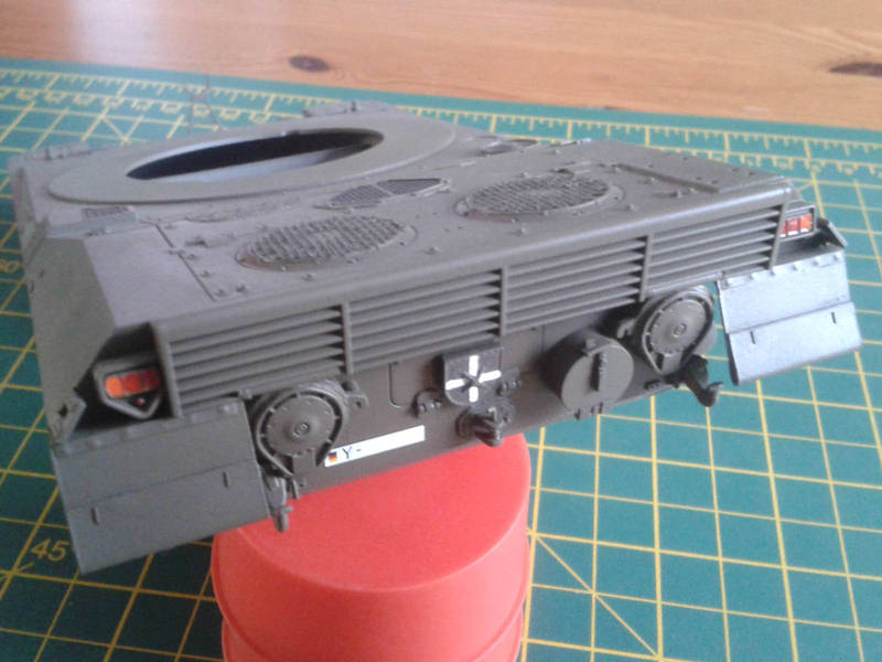
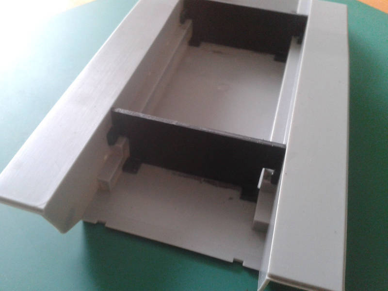
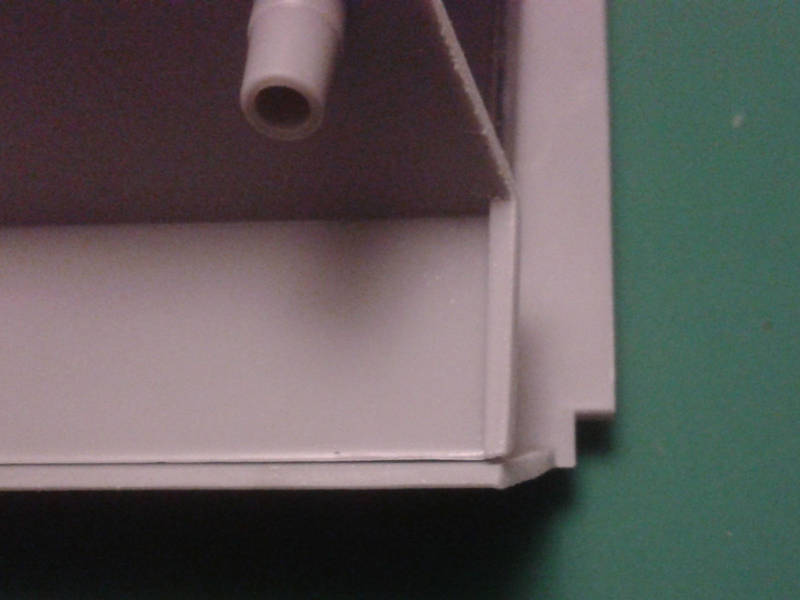
Anyway, on with the build! Starting with the hull, I added braces that measure 60mm across at the top, 50mm across the bottom, and 23mm tall. (These are notched to fit around the bulge in the lower side walls.) I made sure the sides and bottom edge were square, and pushed them down to counteract the floors tendancy to bend upwards when the sides are straightened. Anyone who has built a DML/CH Sherman will know the problem!
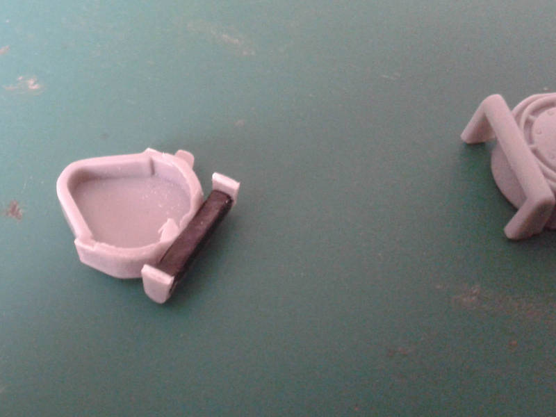
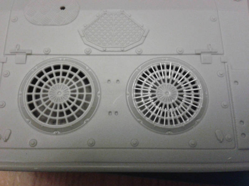
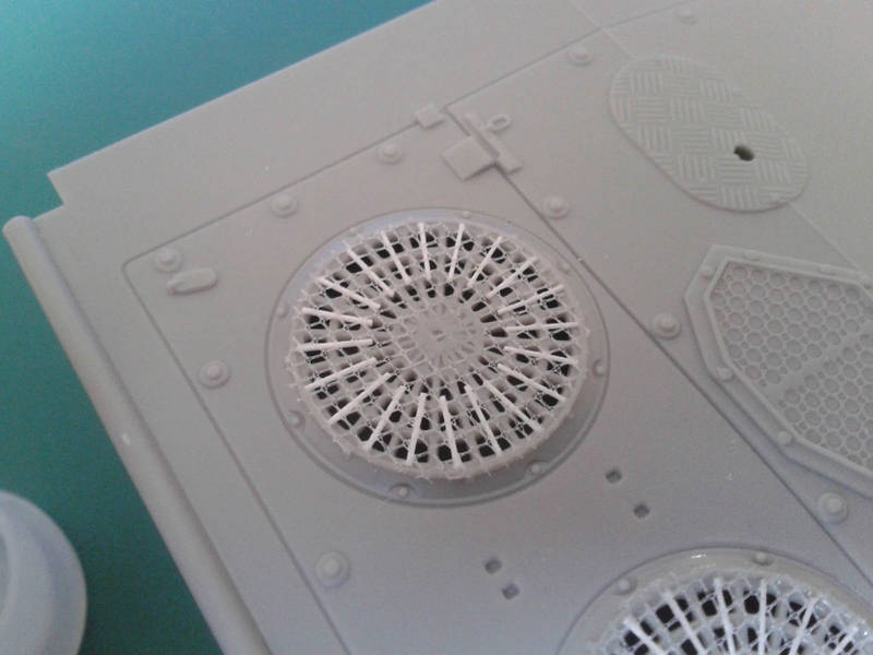
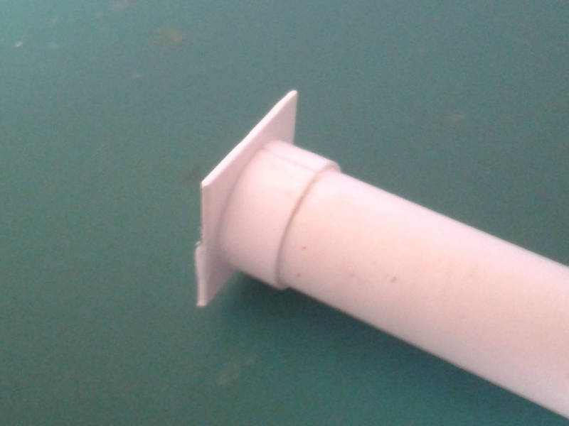
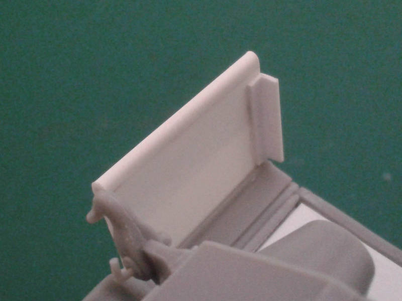
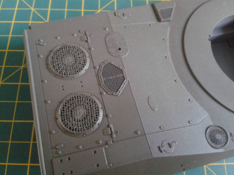
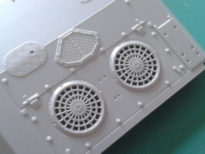
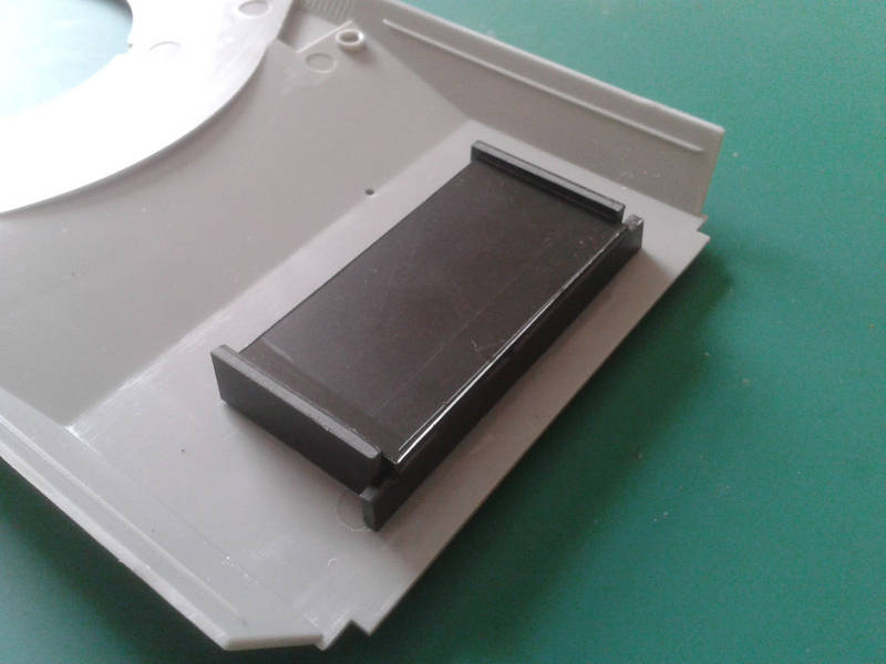
I noticed the fans leave big holes, so built a shadow-box under them. I had some black plastic handy, but could have just painted white Evergreen if needs be. This box also helps stiffen the otherwise-bendy engine deck.
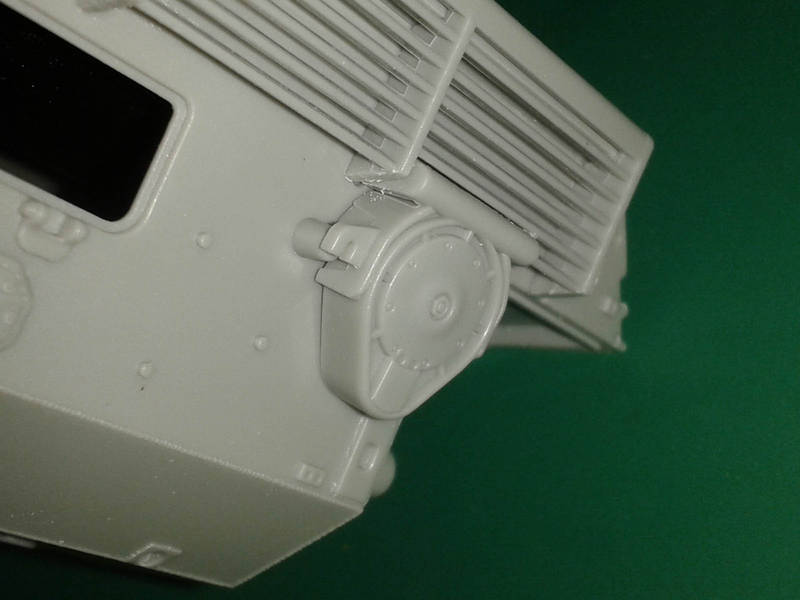
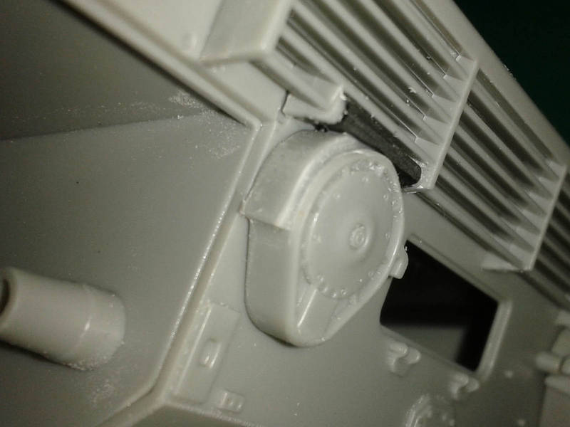
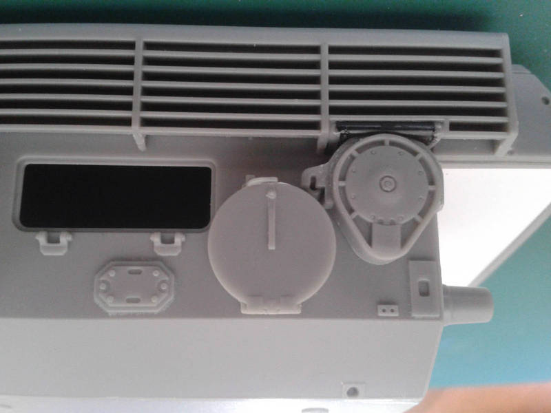
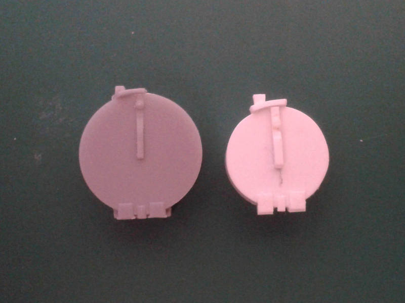
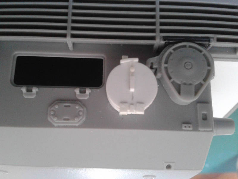
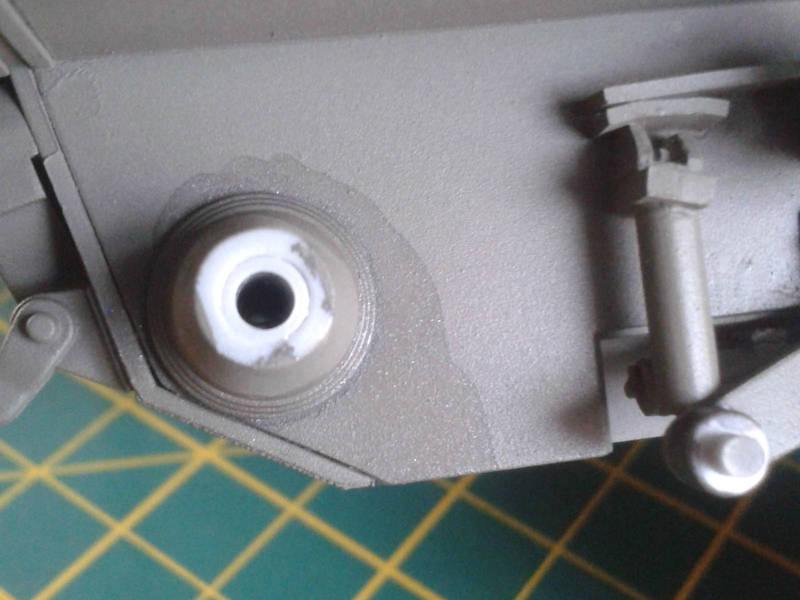
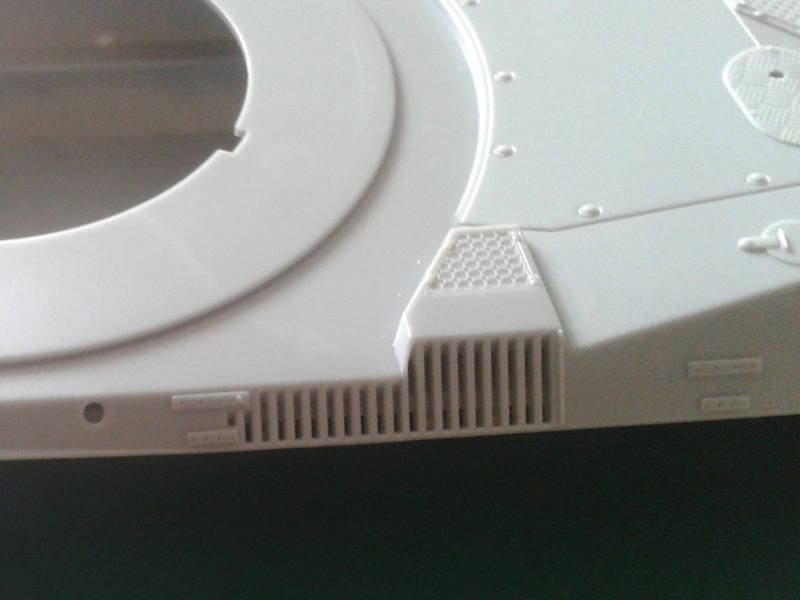
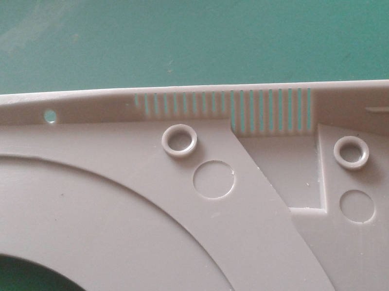
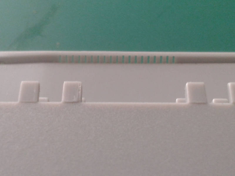
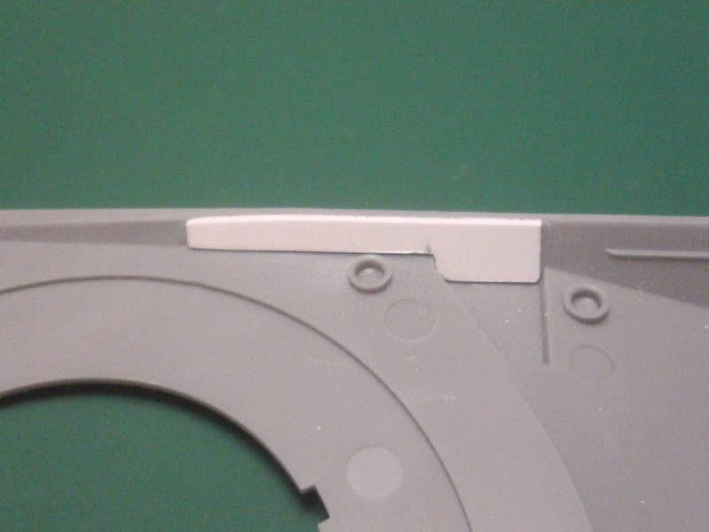
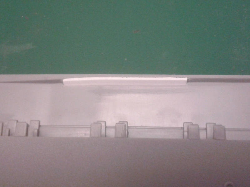
The other thing that needs doing before the hull is closed up is the side grille. On the real one this is filled (by a filter? Cant tell) so I didnt want it see-through. Besides, DML did something odd with the sponson floors that means they sit about 2mm too high, rather than lining up with the bottom edge of the hull. This is all too visible with empty grilles. I used some plastic, notching the sponson floor to fit. I could also fix the sponson floors with an extra skin of plastic you wont see it from most sensible angles, so it is optional. I cannot help wondering if the designers of the top and bottom werent on speaking terms
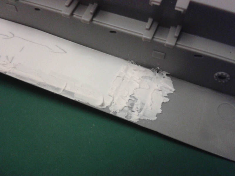
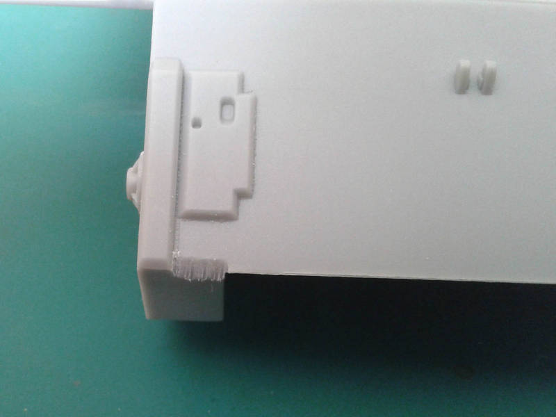
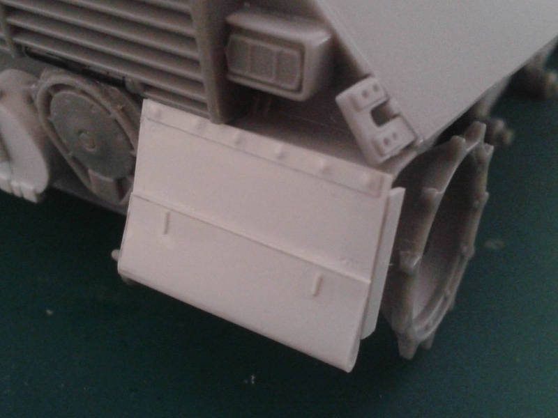
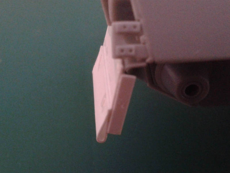
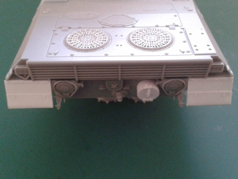
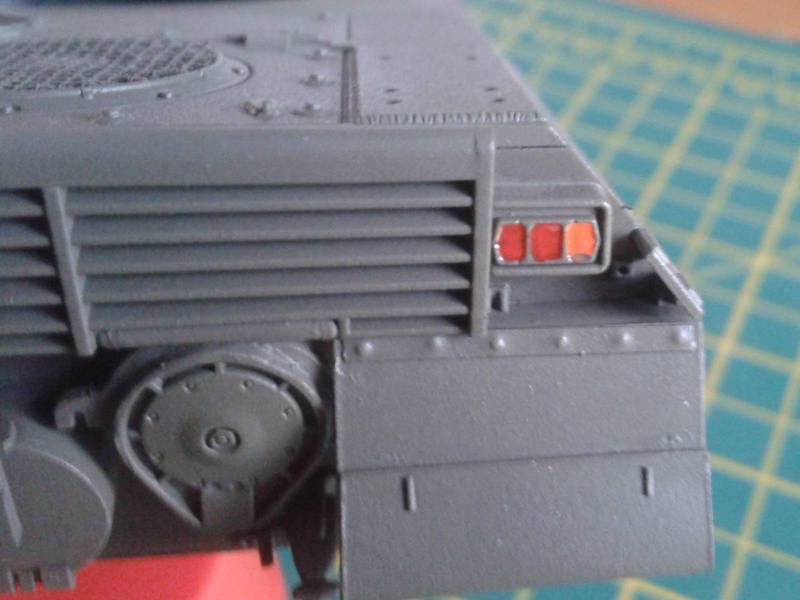
When I finally assembled the hull I noticed the sponson floors are a poor fit (just like their Shermans?...) and the lower hull is about 1mm too long, just enough to leave a gap between the rear plate and upper hull sides. This was fixed by filing the rear end of the lower hull (Grrr!) until everything fit. Note that adding the slats on the rear helps stiffen everything up. I had to sand the front edges of the sponson floors to get a decent fit that still needs putty and sanding. Oh, and the upper hull had a slight upwards warp, so I needed to use tape to hold things tight while the glue worked.
Anyhoo thats enough for the first instalment! More will follow shortly