_GOTOBOTTOM
Armor/AFV: Braille Scale
1/72 and 1/76 Scale Armor and AFVs.
Hosted by Darren Baker
Zvezda's Tiny Terminator Build
firstcircle
Visit this Community
England - South East, United Kingdom
Joined: November 19, 2008
KitMaker: 2,249 posts
Armorama: 2,007 posts
Posted: Sunday, March 19, 2017 - 04:58 AM UTC
This sample that Zvezda sent to Jim has found its way to me for review. Since I know almost nothing about the real thing, a build review is really the only way to go, so I thought I'd blog it as I go, then wrap it up at the end with a summary build review.

So this is the box top - same illustration as their 1/35 version:


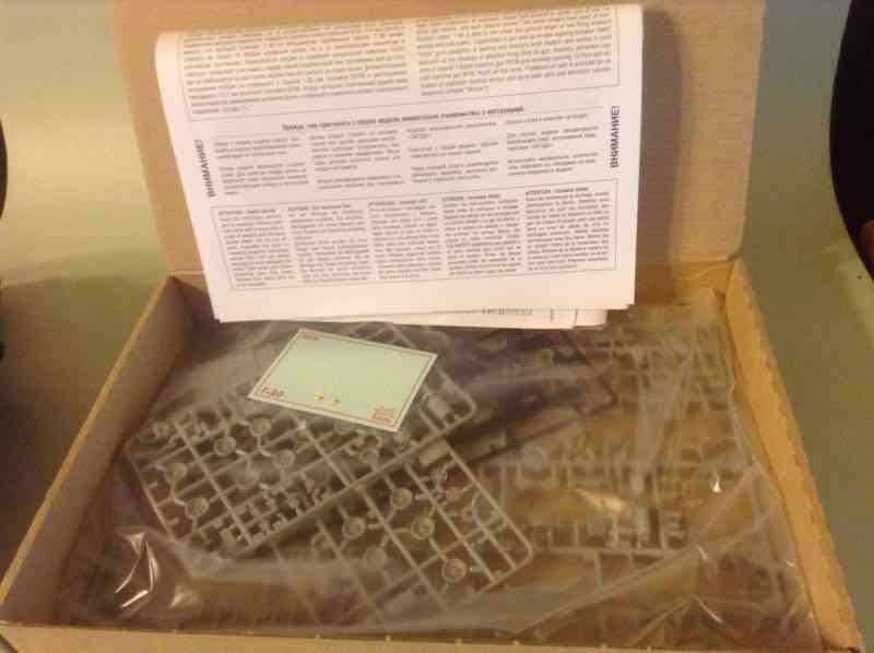
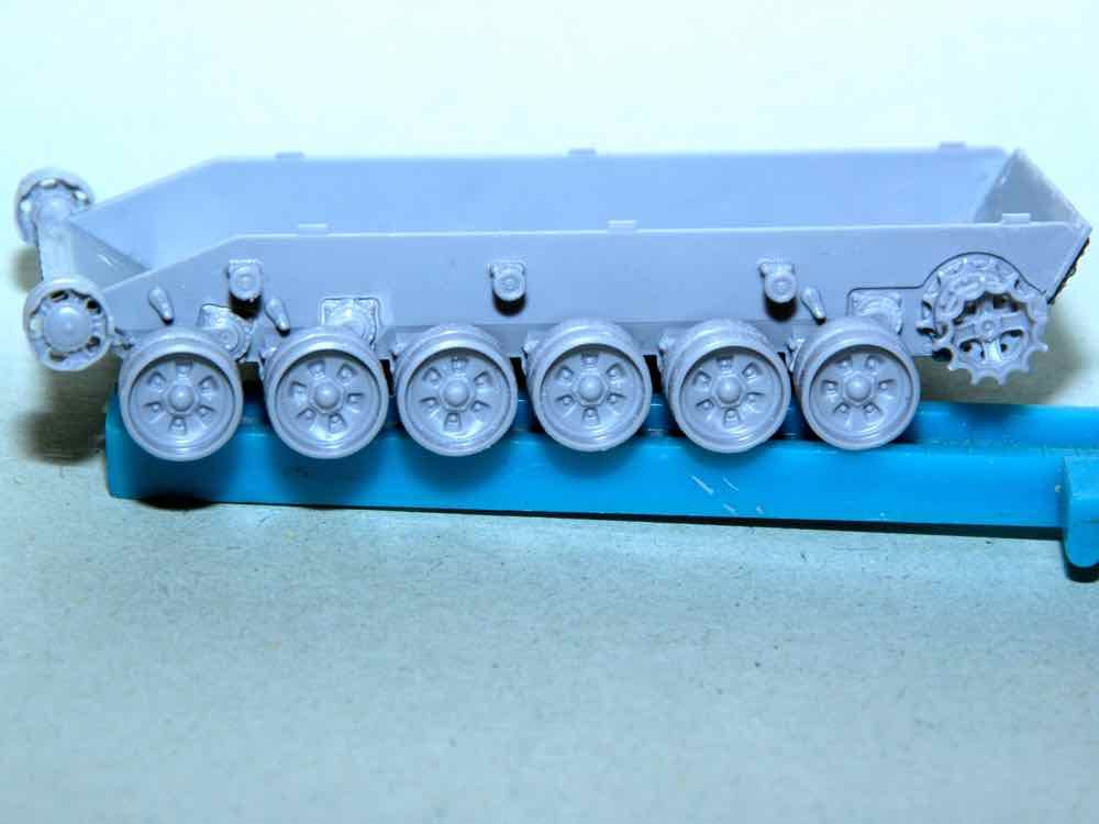
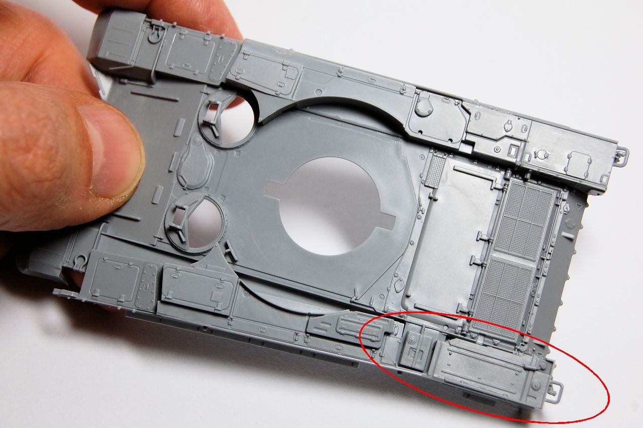
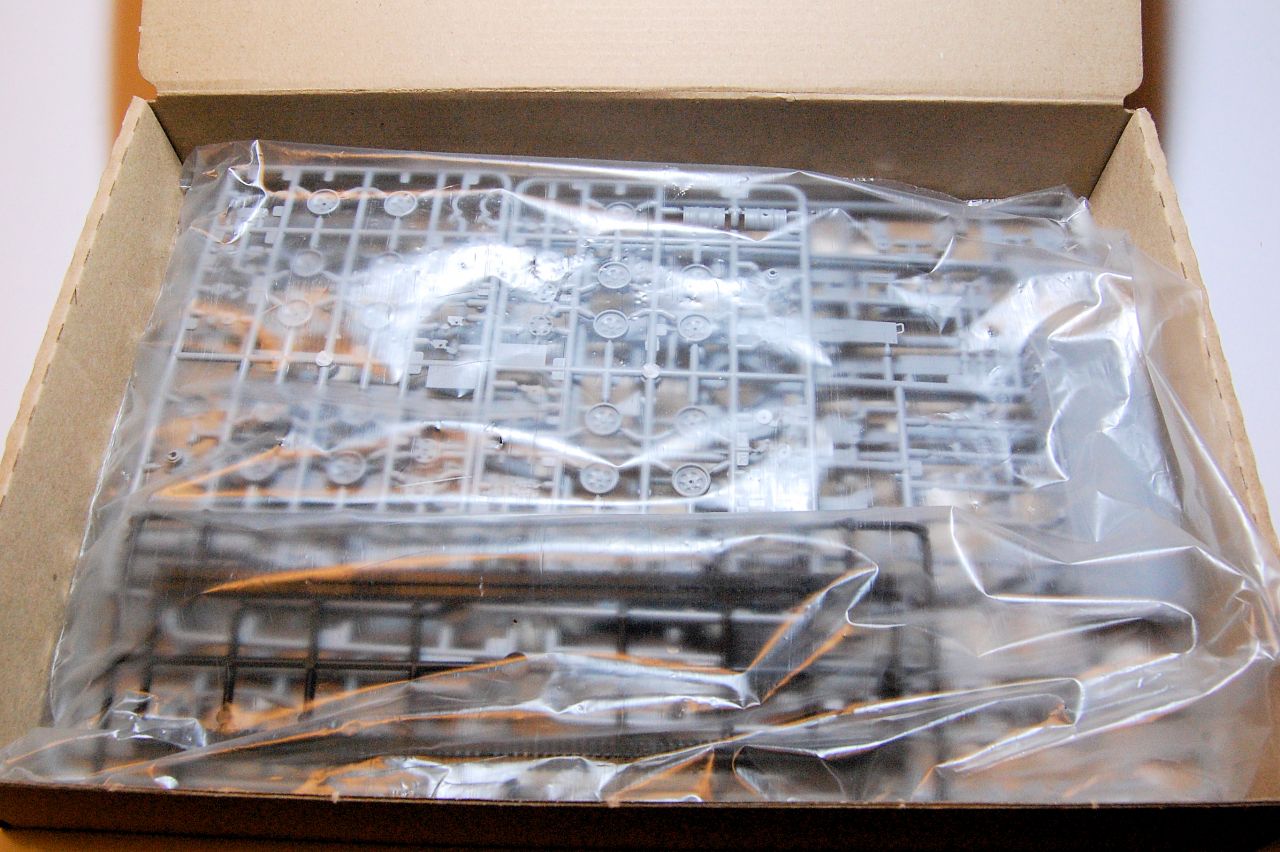
That box is actually a flimsy end opening sleeve for a useful hinged corrugated "pizza" box within. Straight away we can see this is a different type of kit from the Zvezda WWII snap together kits: the box is much bigger, and it says it has 197 parts. This is the view inside:


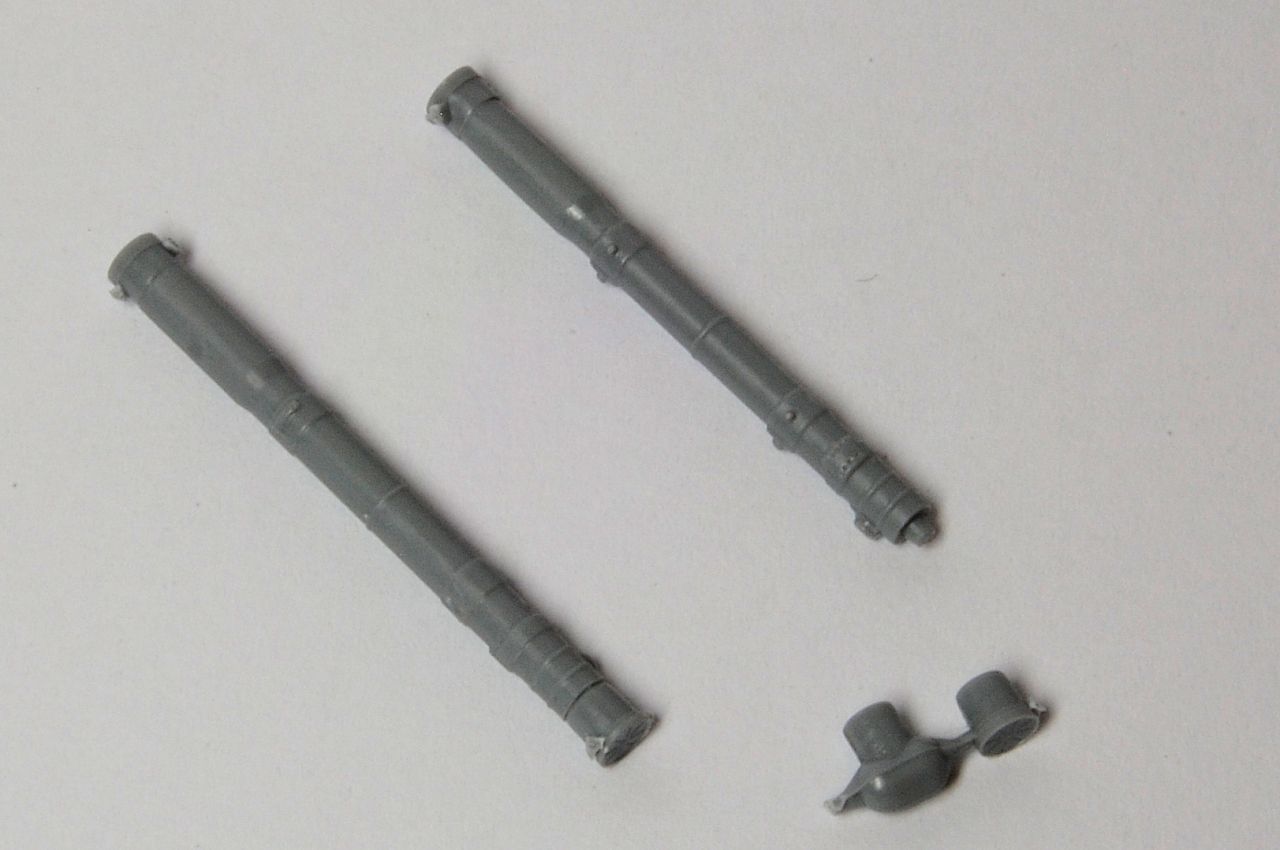
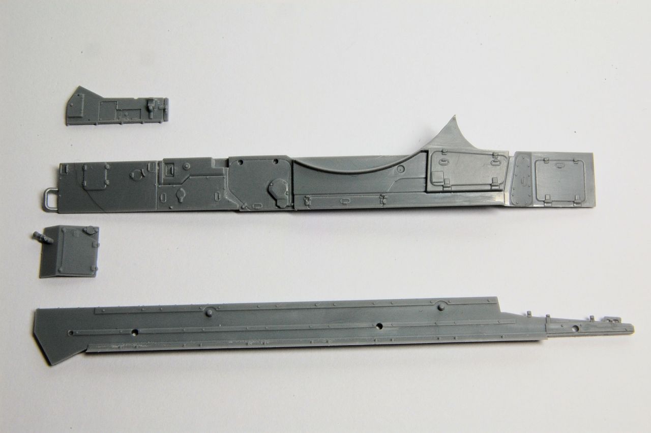
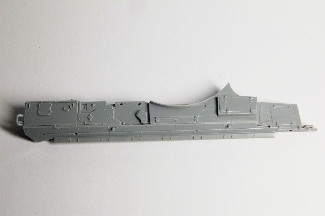
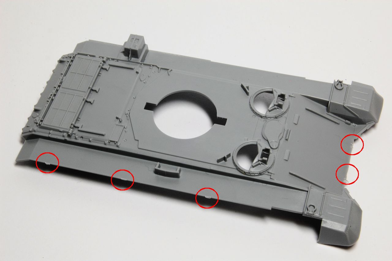
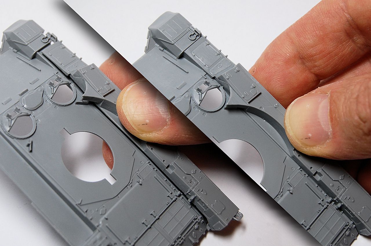
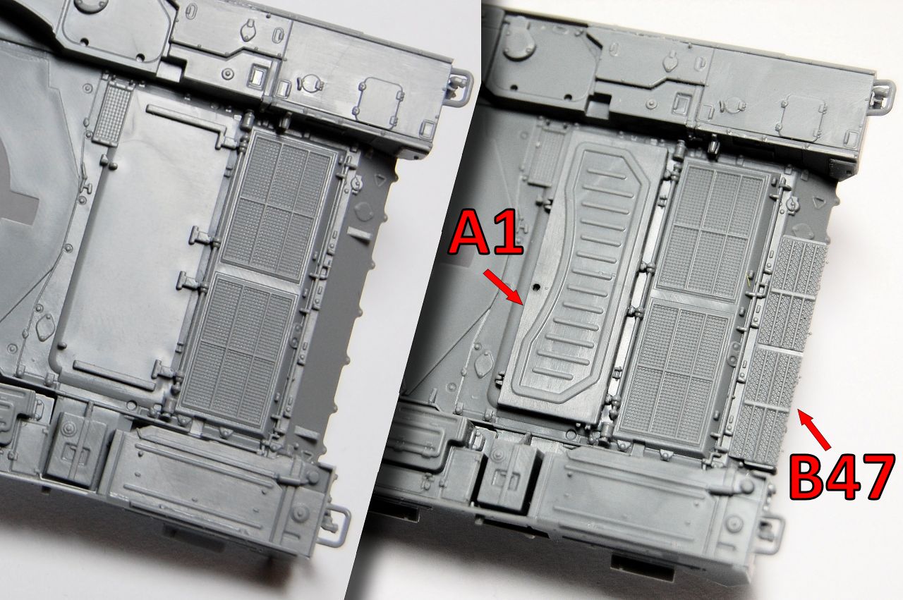
I'll save sprue shots for the review, for now I'll proceed with the first steps of construction:


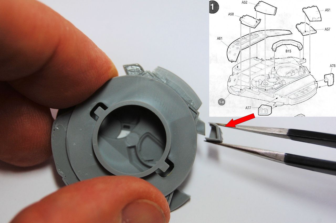
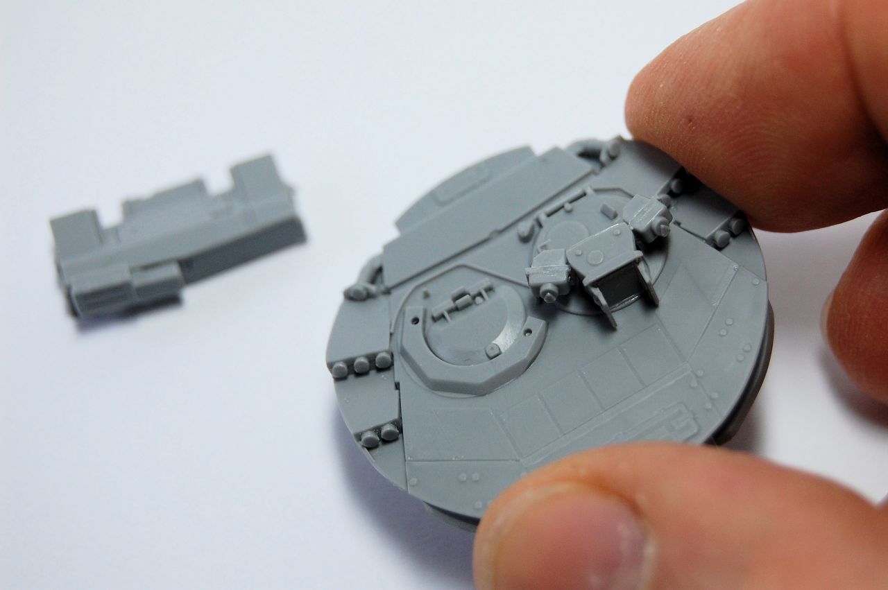
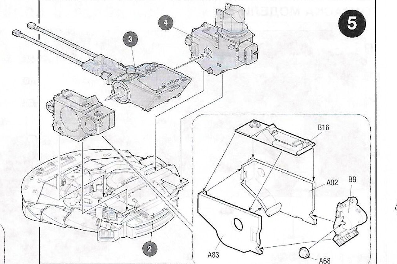
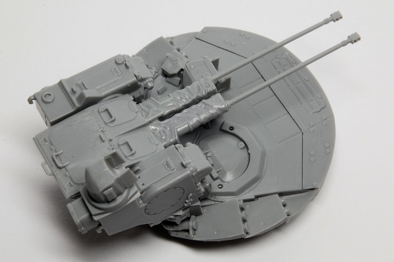
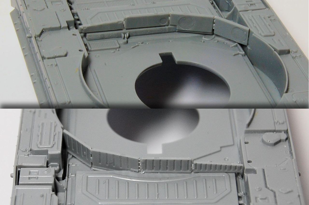
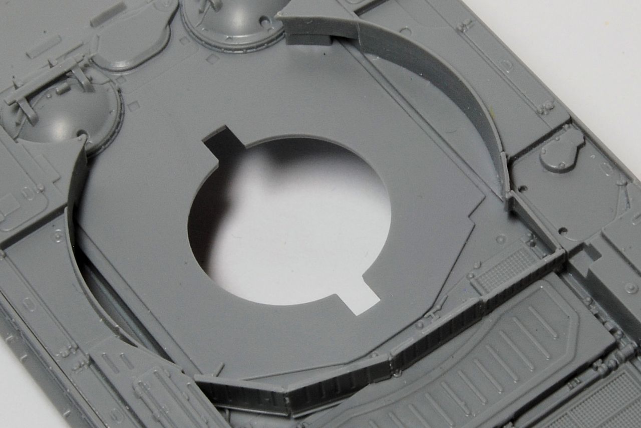
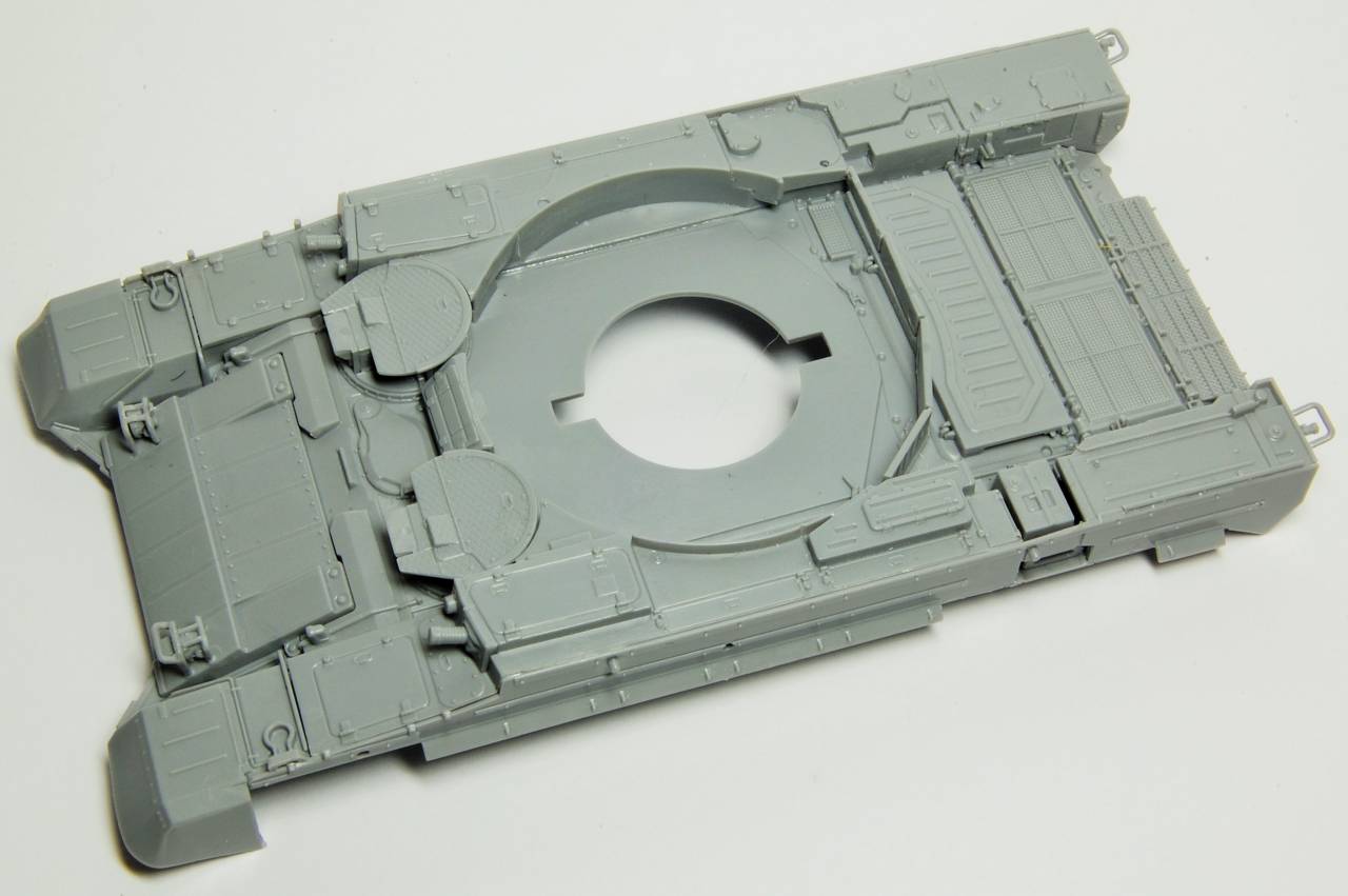
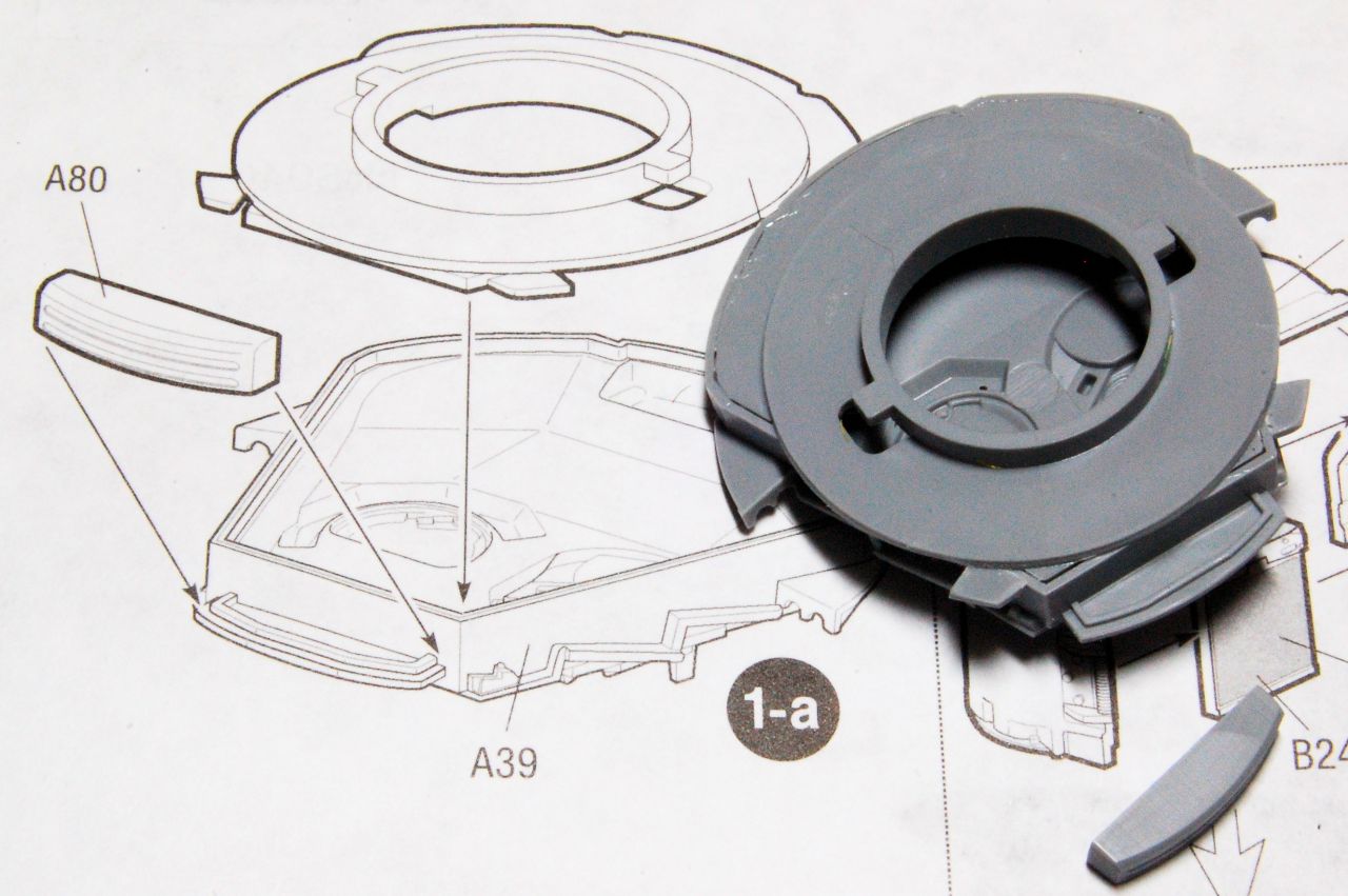
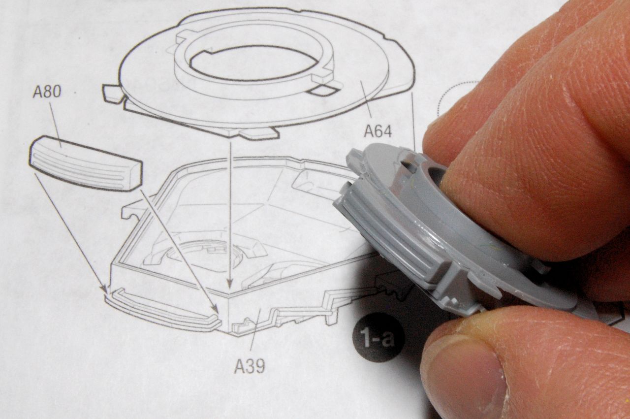
This is so different from building something like a Panther that I'm unsure what everything is called, although it does have a turret (I think). We start by inserting the base of the turret into the turret superstructure, and then something that might be a box attaches to the back:


That glue looks a bit messy, but it is the underside that will be hidden.
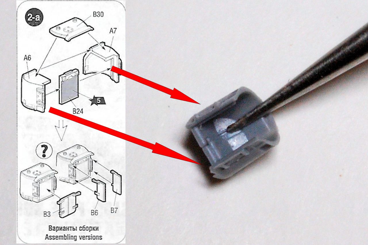
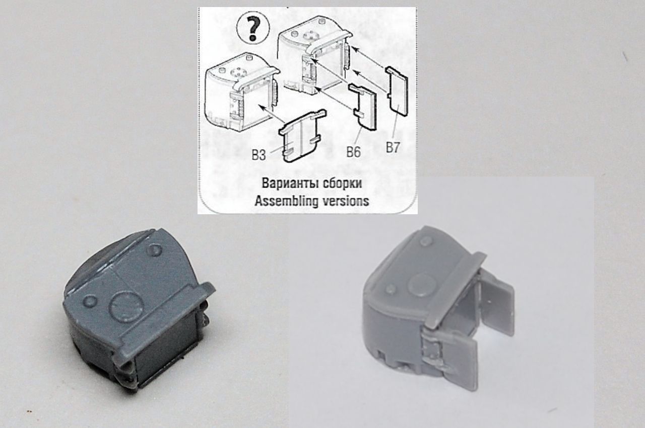
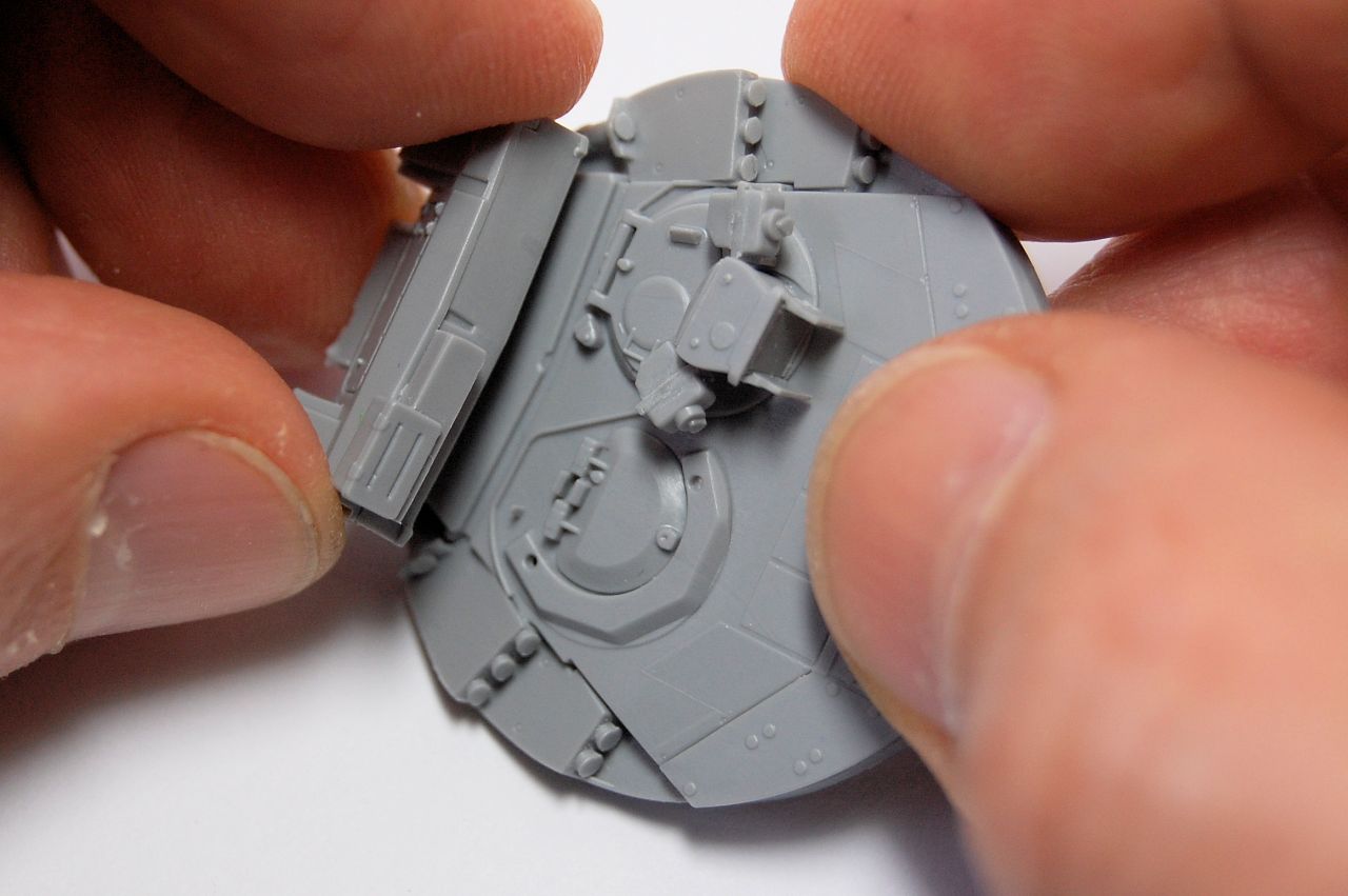
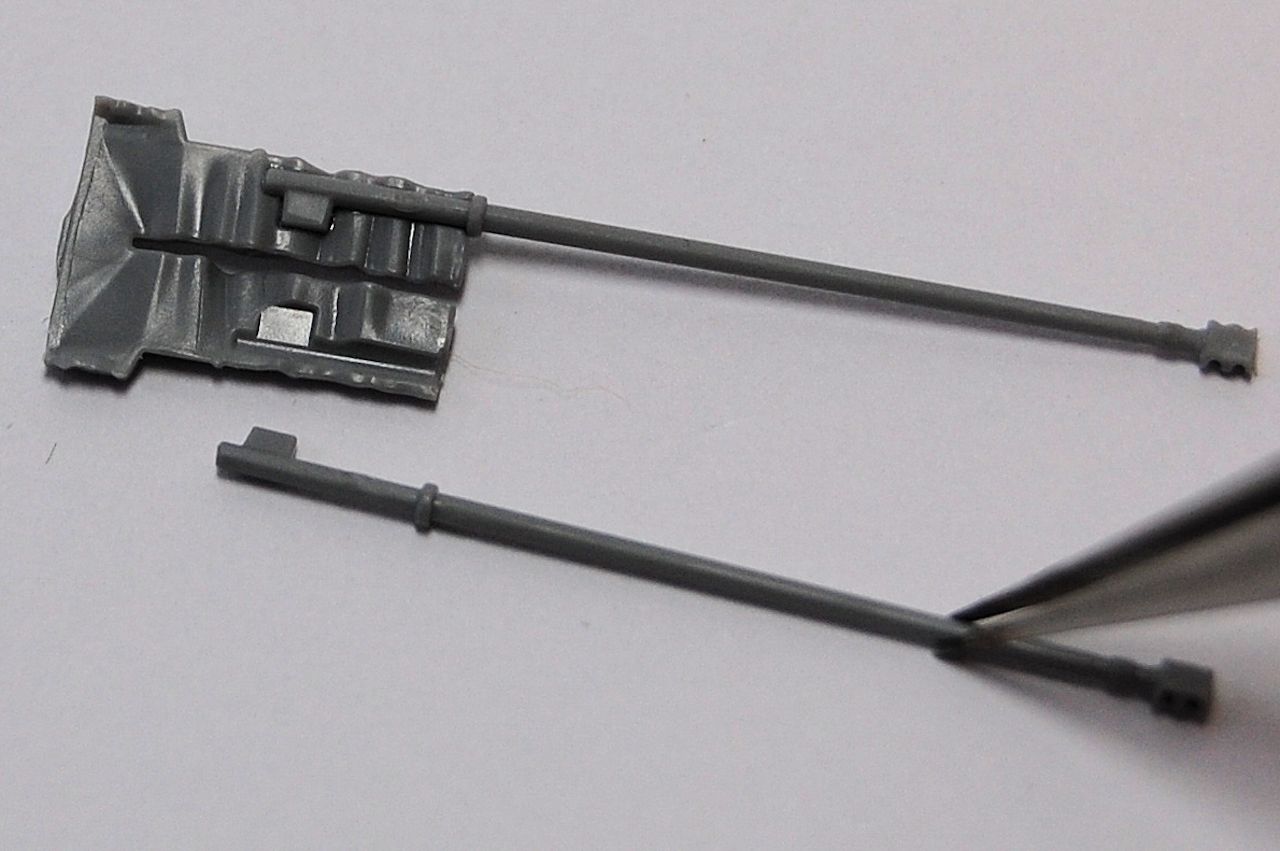
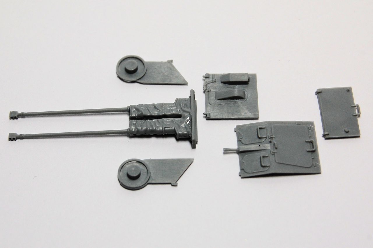
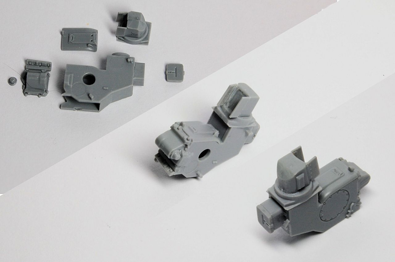
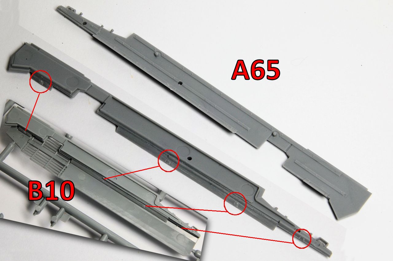
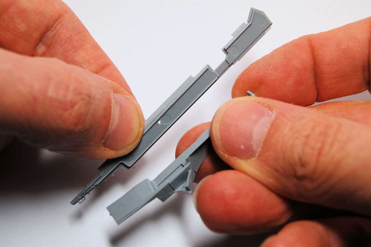
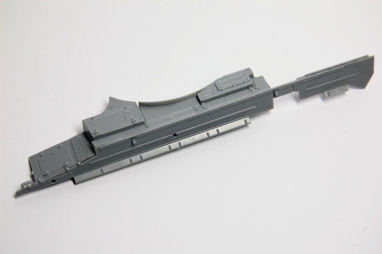
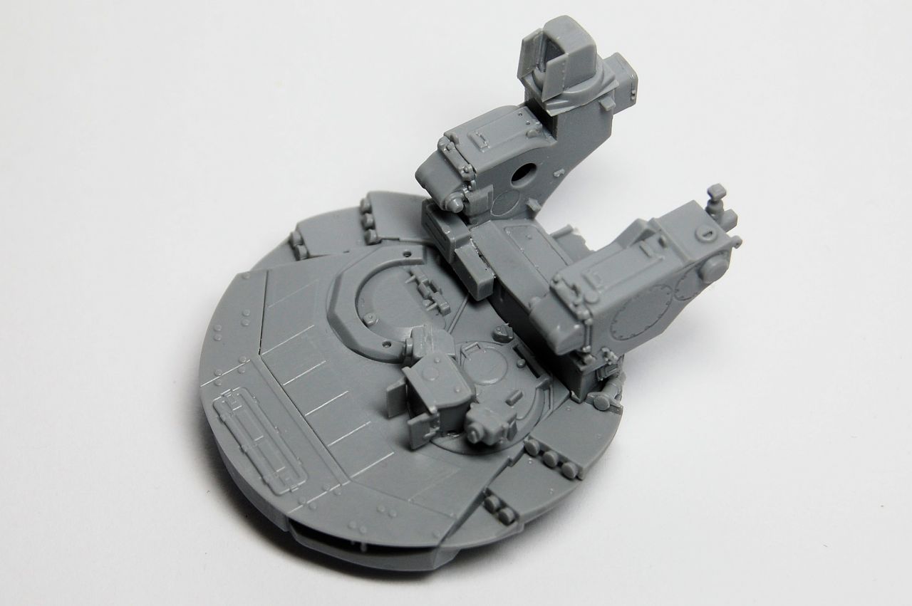
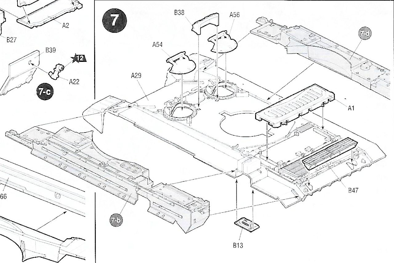
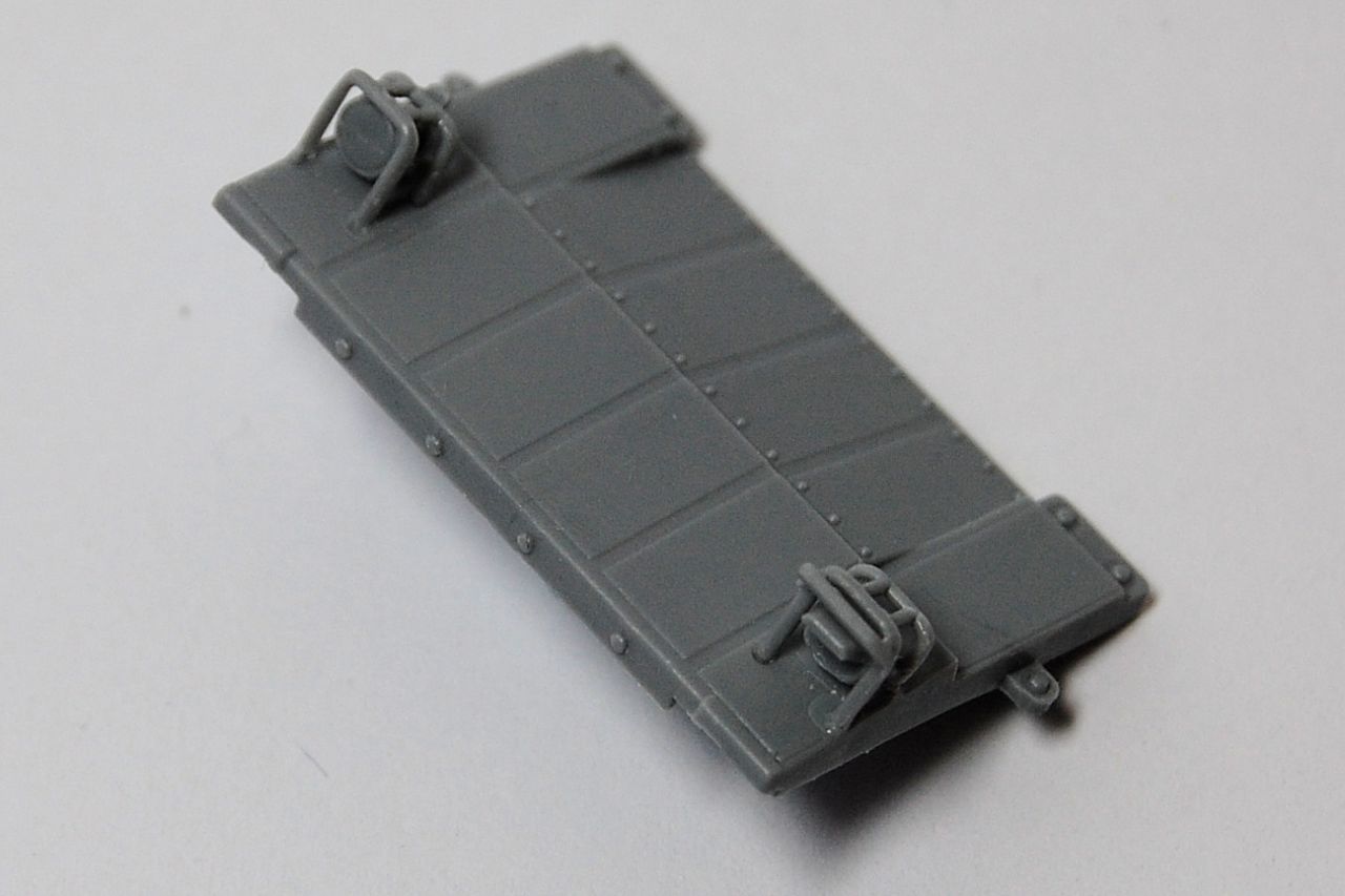
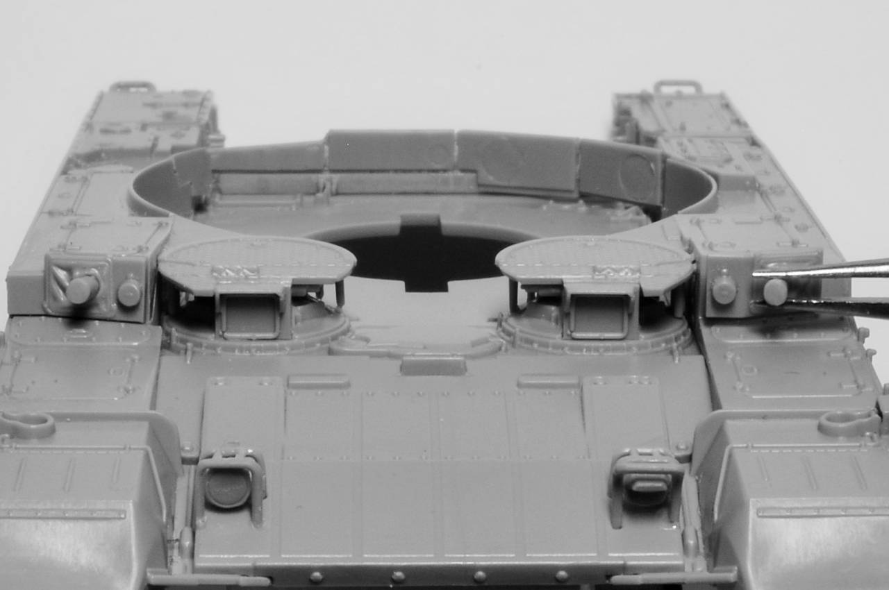
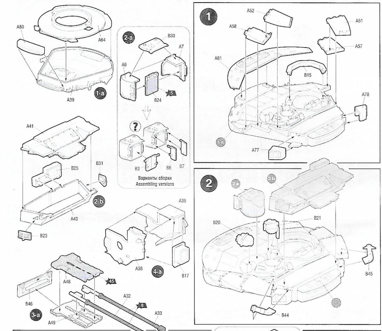
Then we have some other sub-assemblies to be built in preparation for later stages, so 1-a is to be used in 1, 2-a and 2-b to be used in 2, and so on. So 2b is a structure that will attach to the upper rear of the turret and which will, I think, serve as the base for the mounting of the main weapons systems:


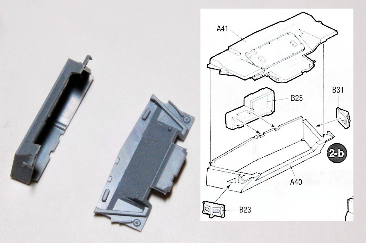
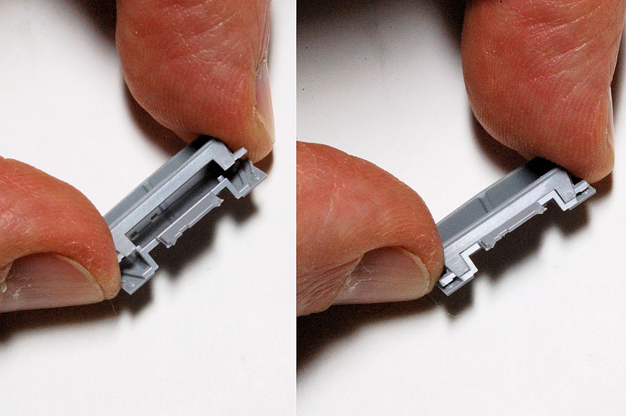
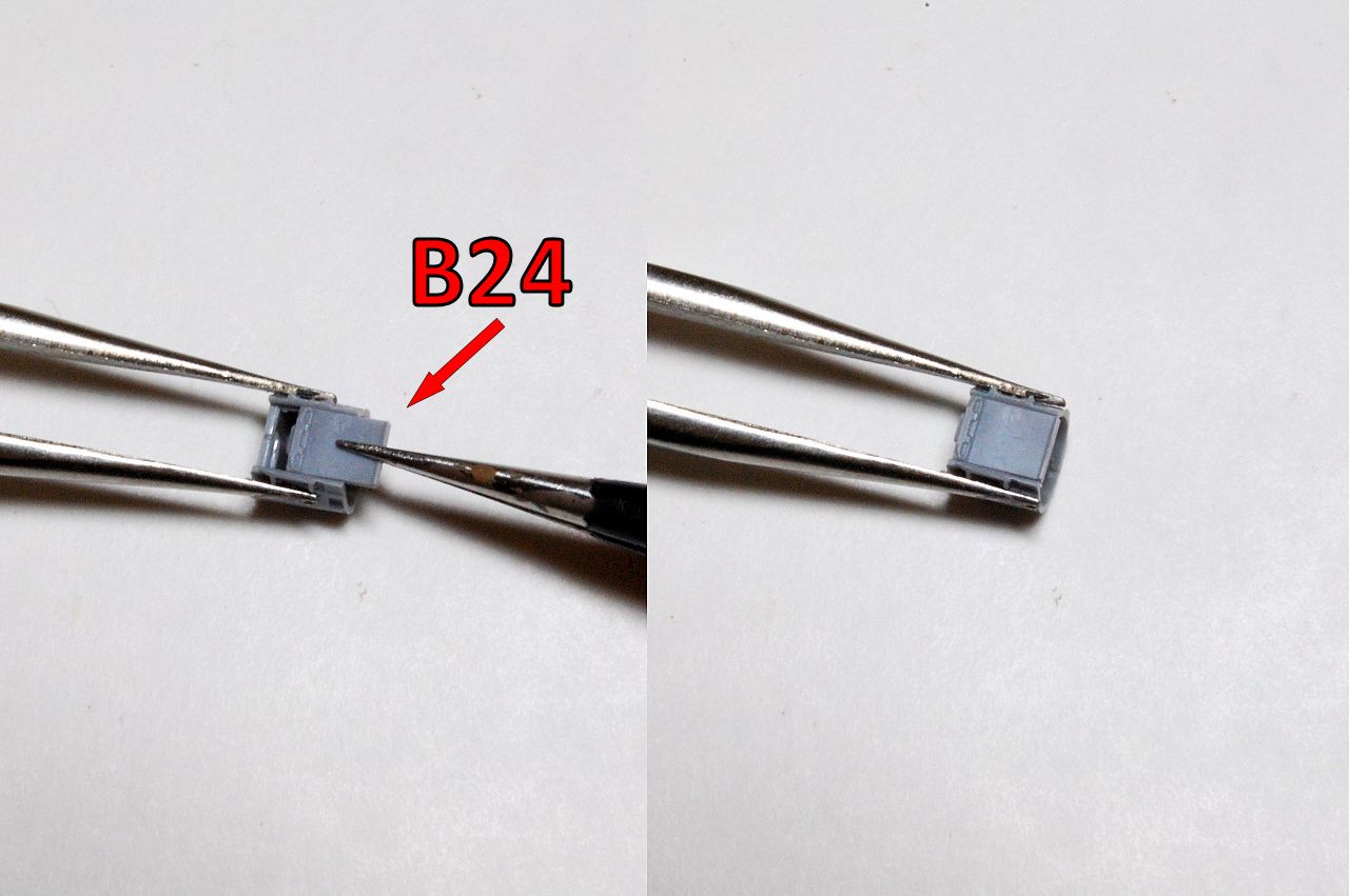
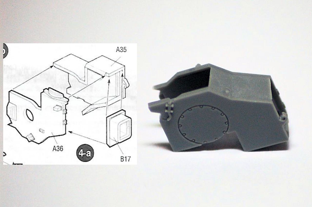
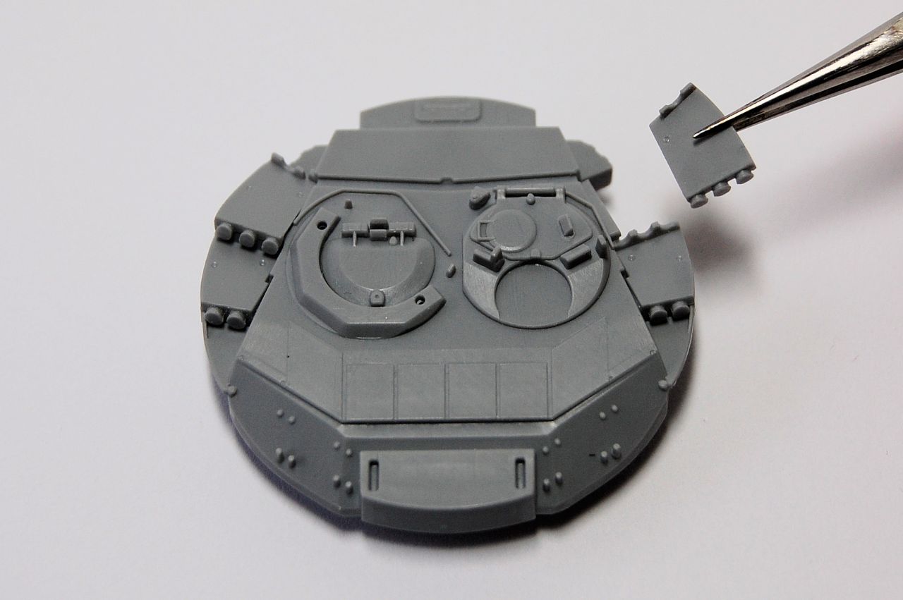
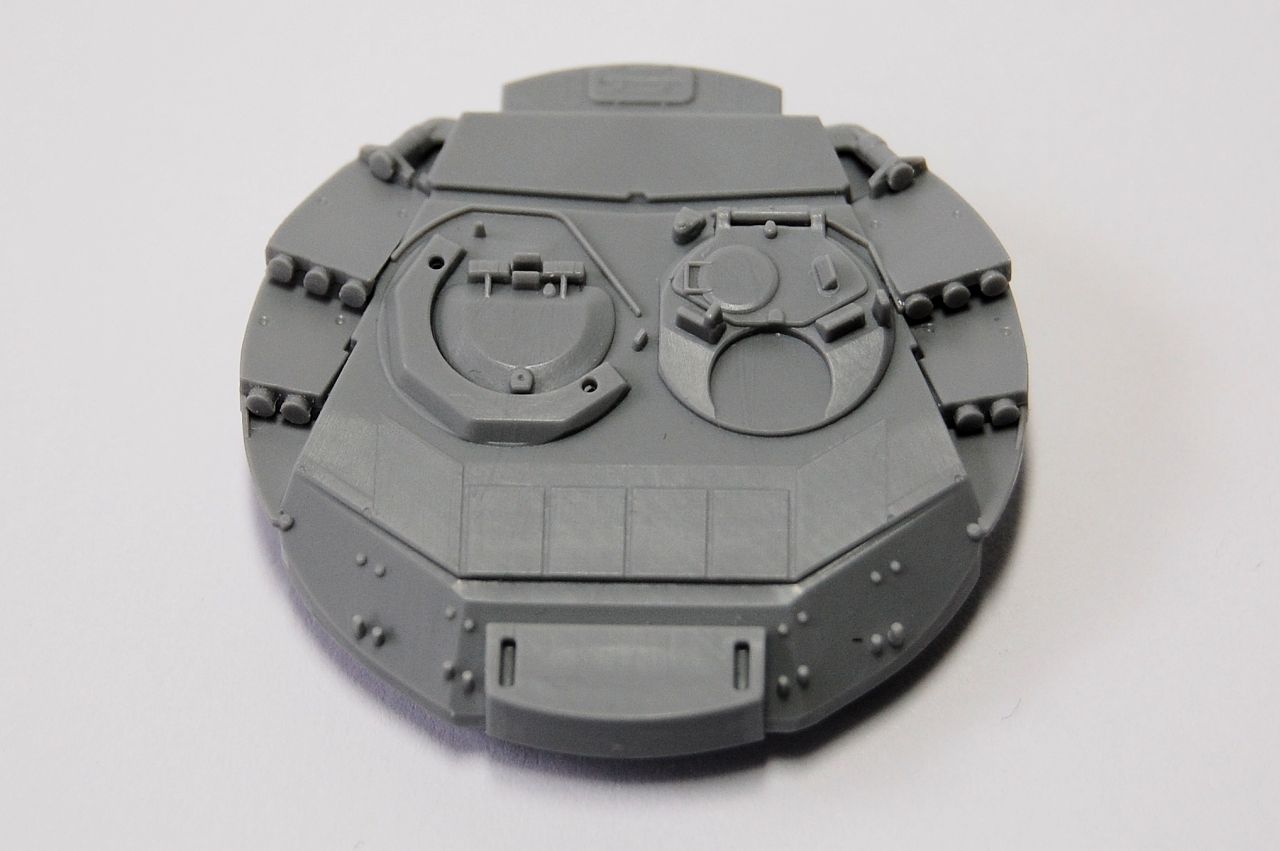
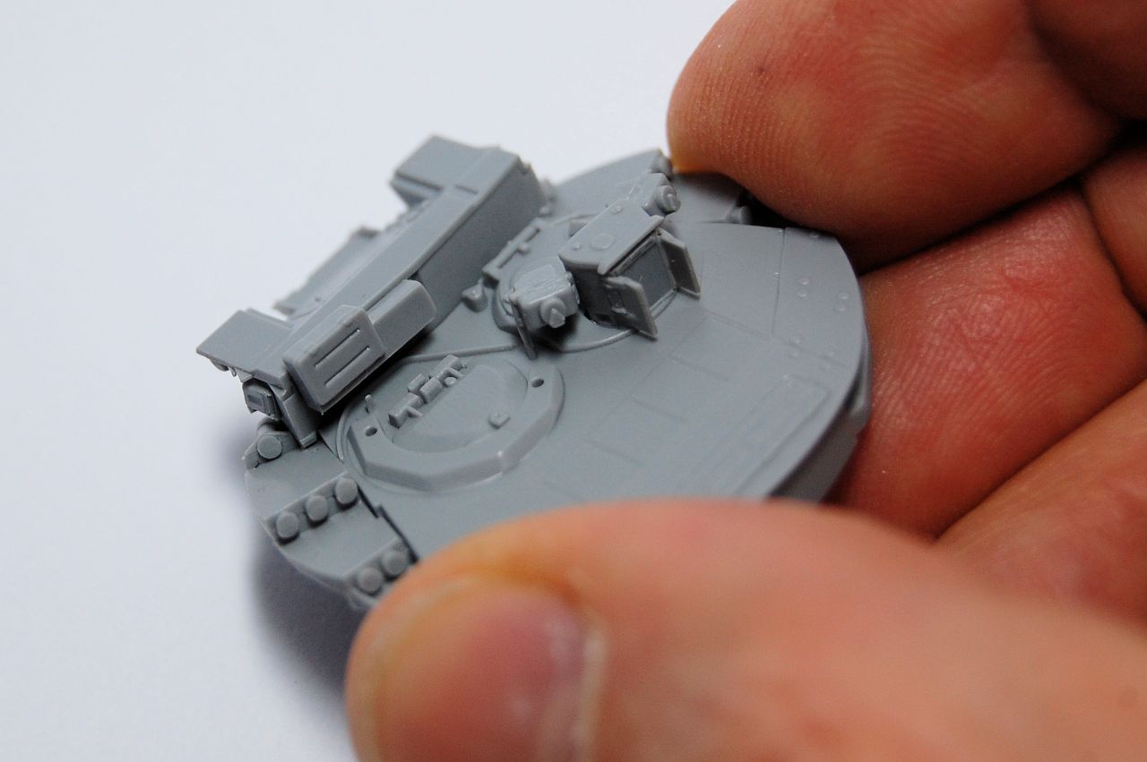
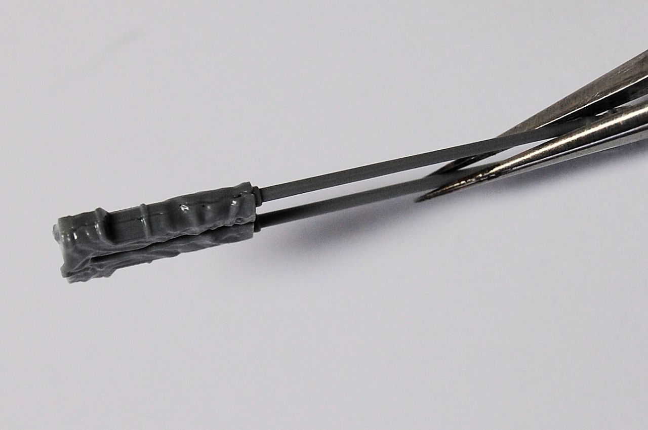
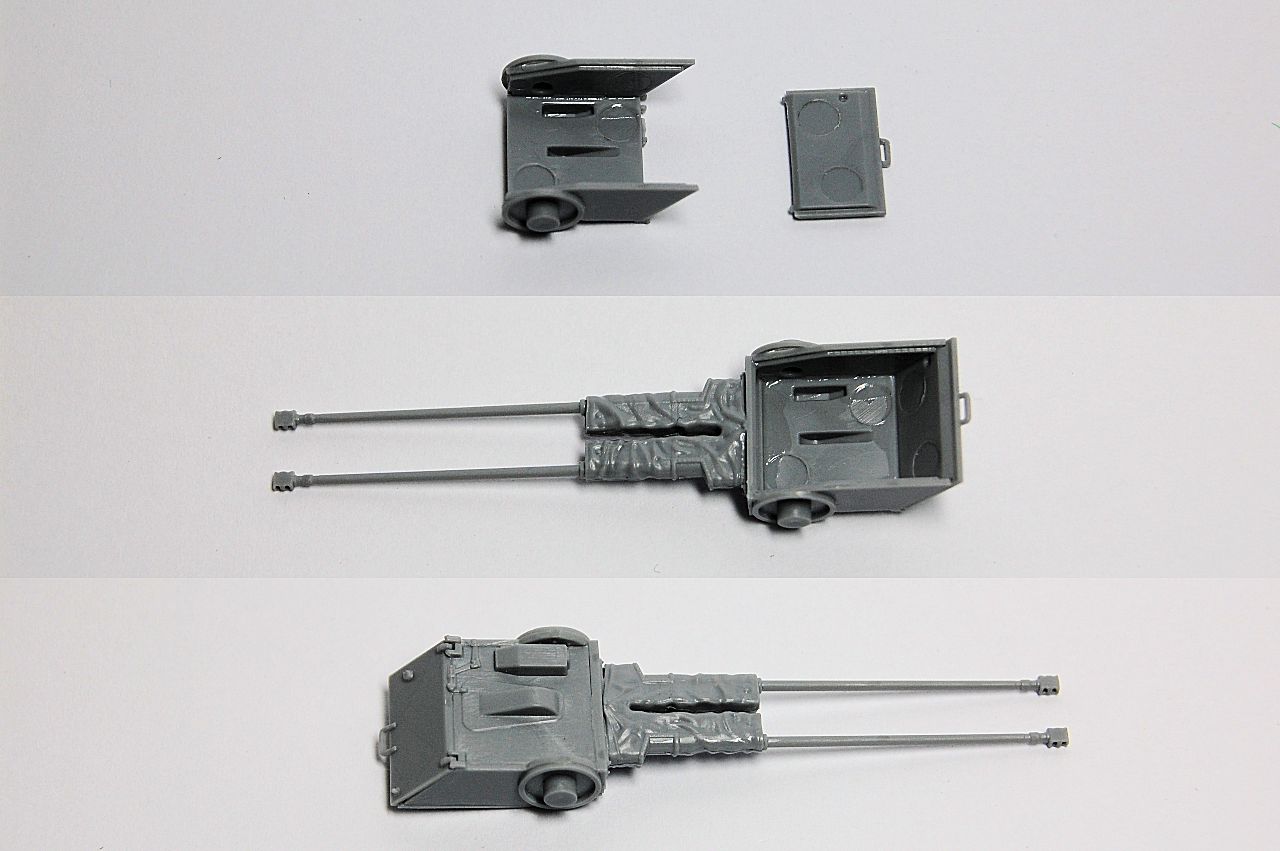
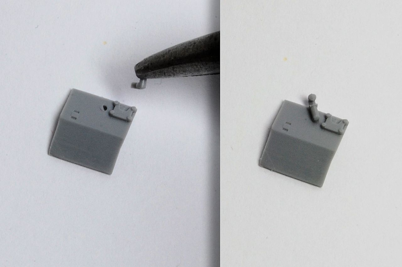
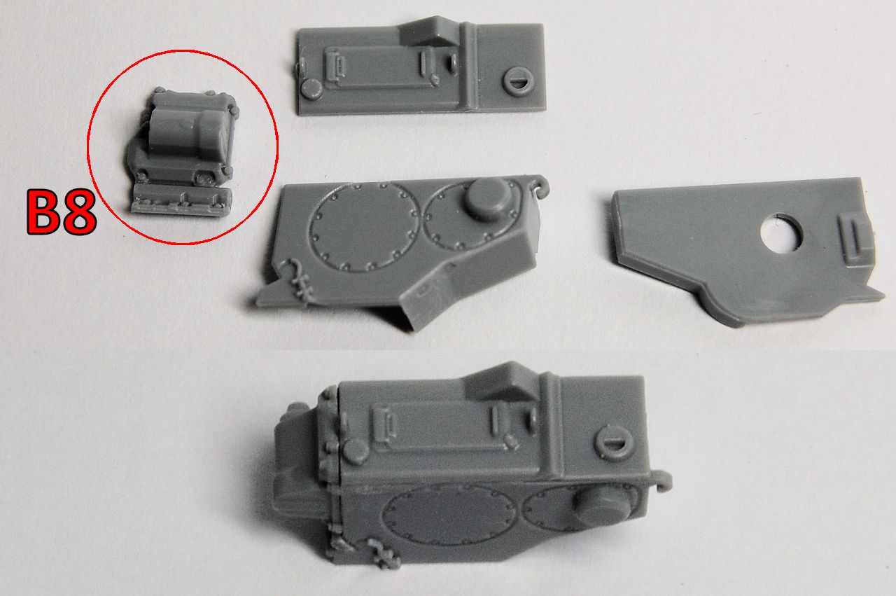
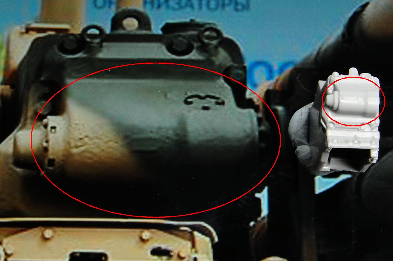
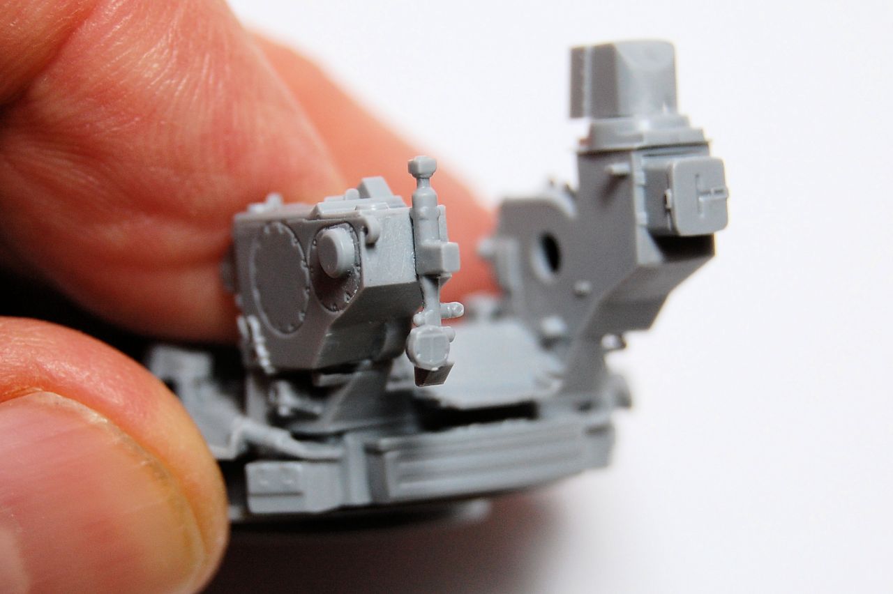
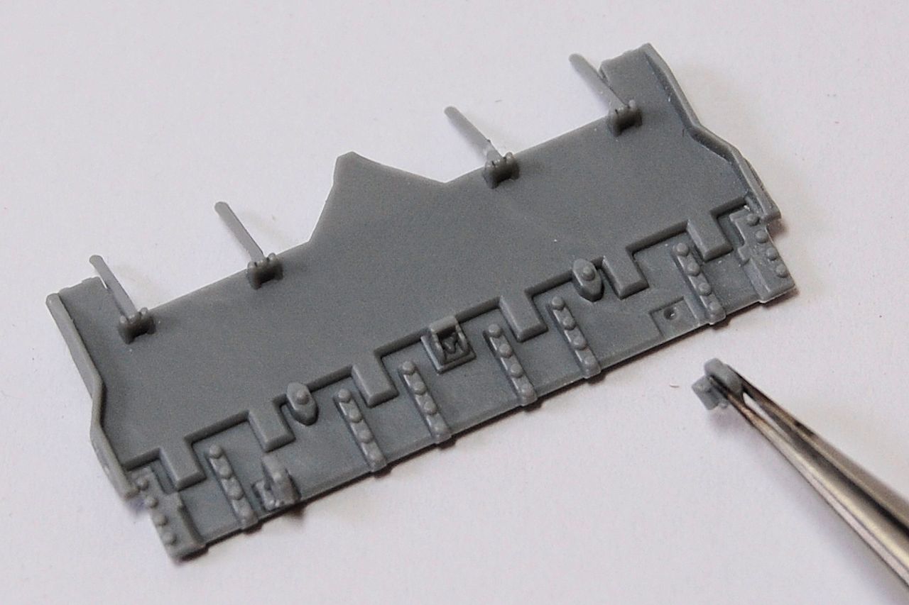
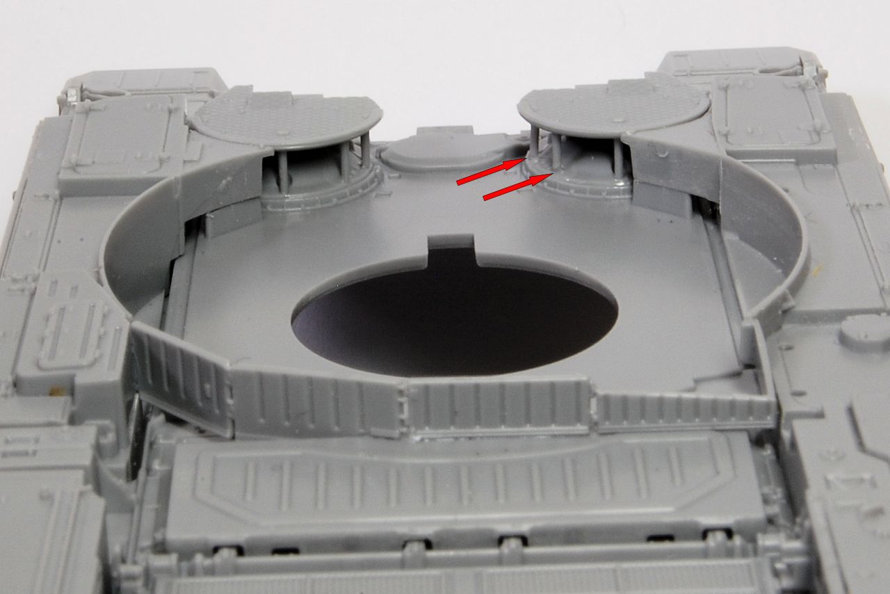
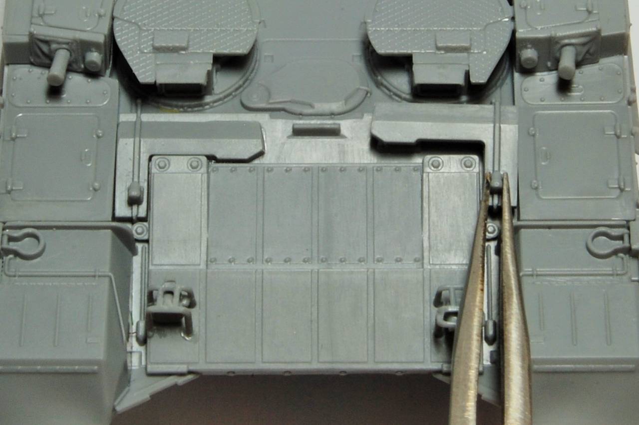
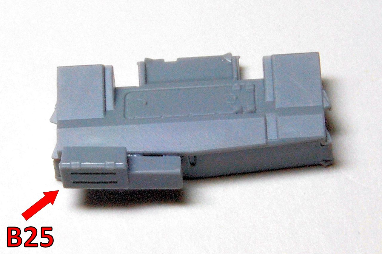
Those fitted together very precisely, and are followed by this, probably a housing for some electronic equipment or something, attaching to the front:

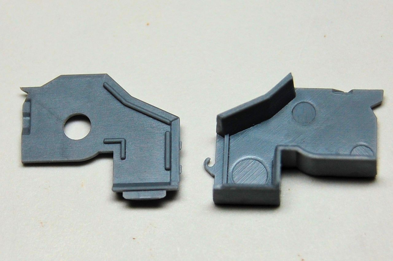
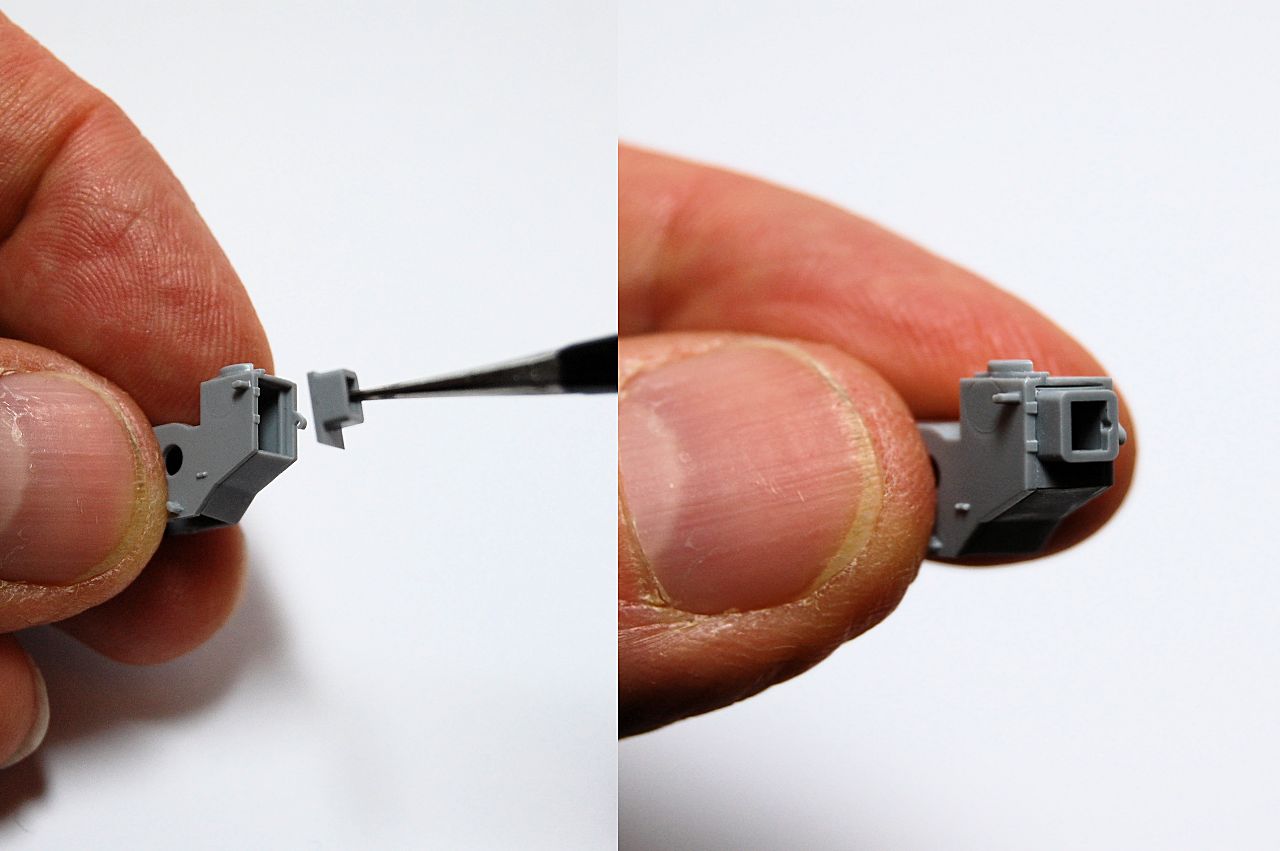
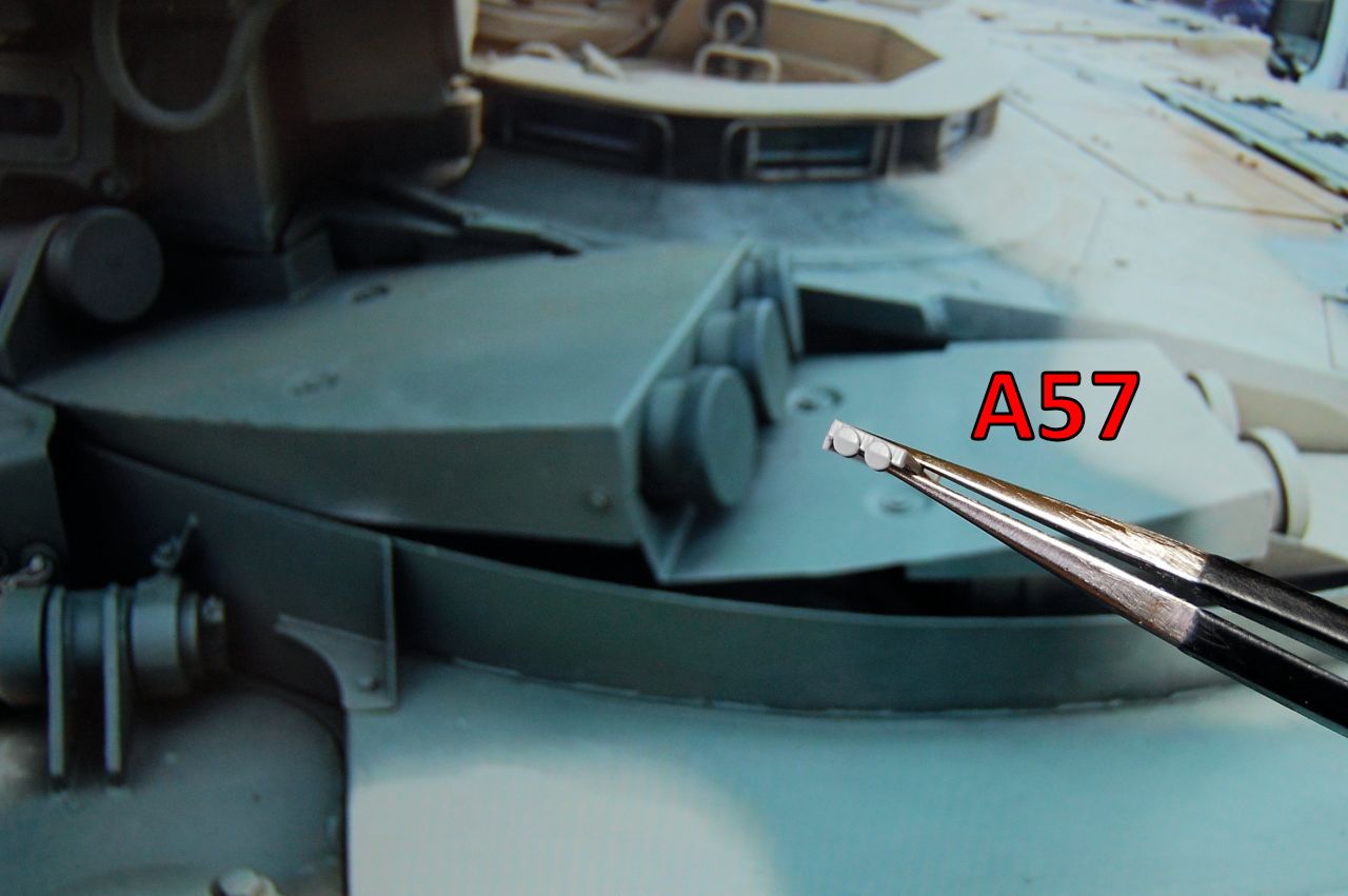
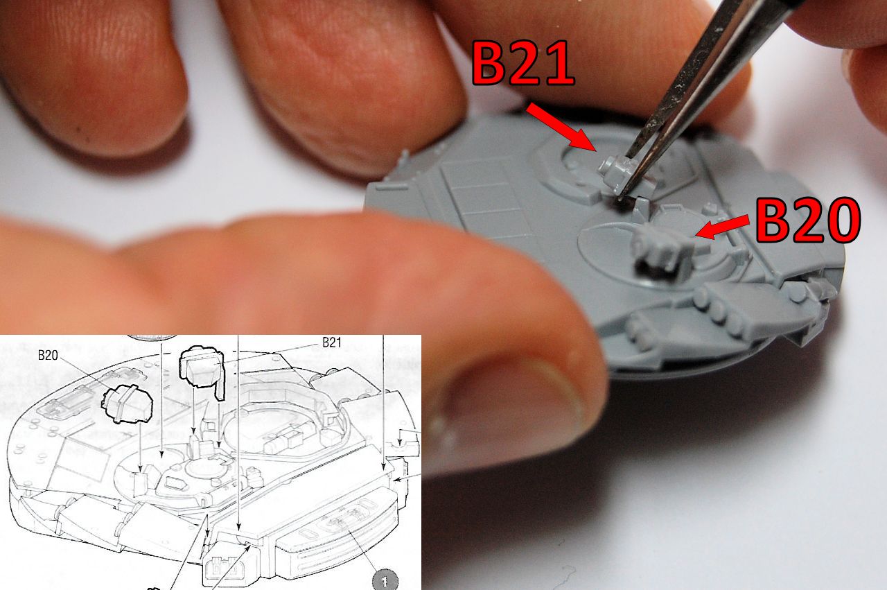
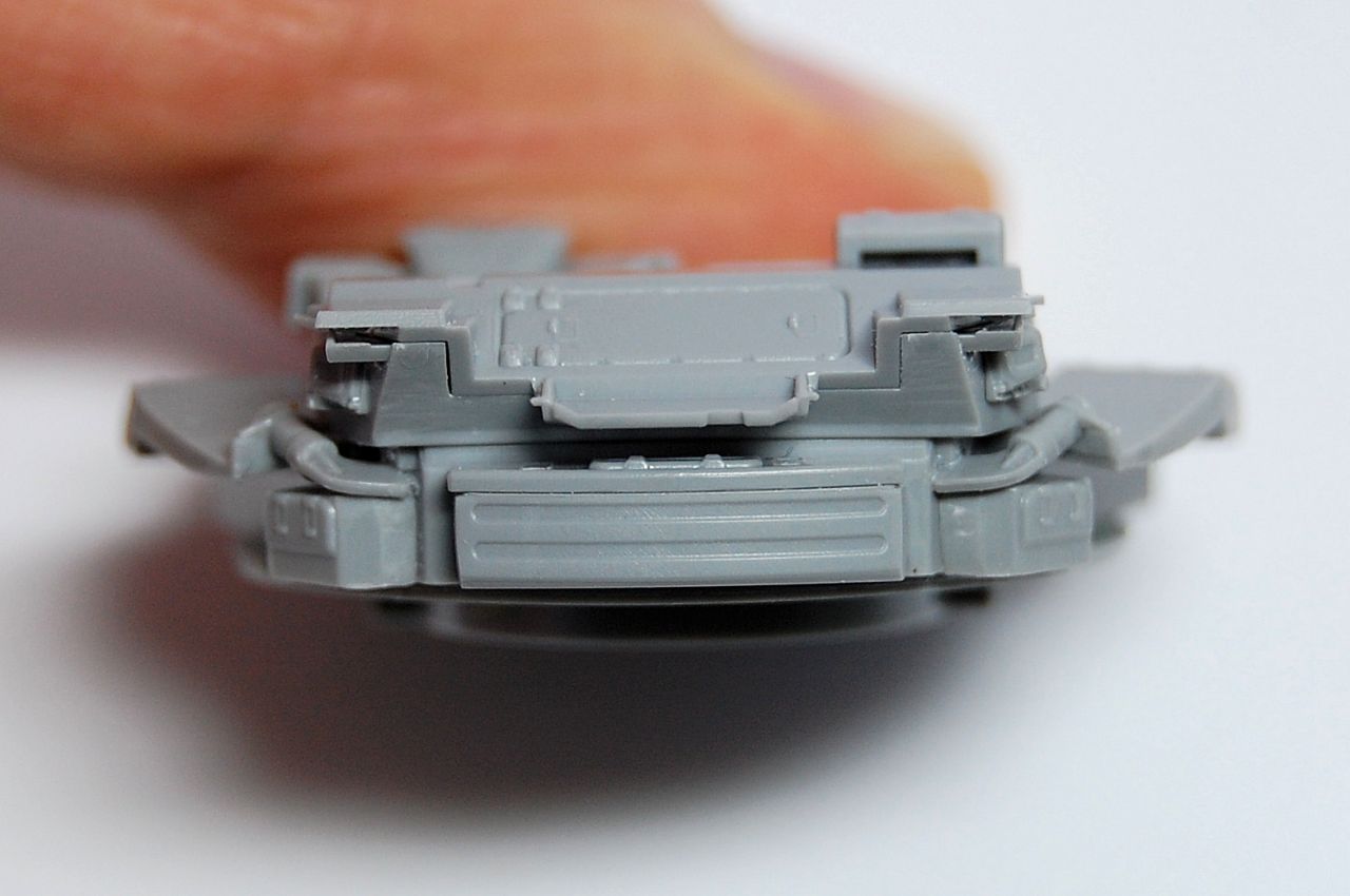
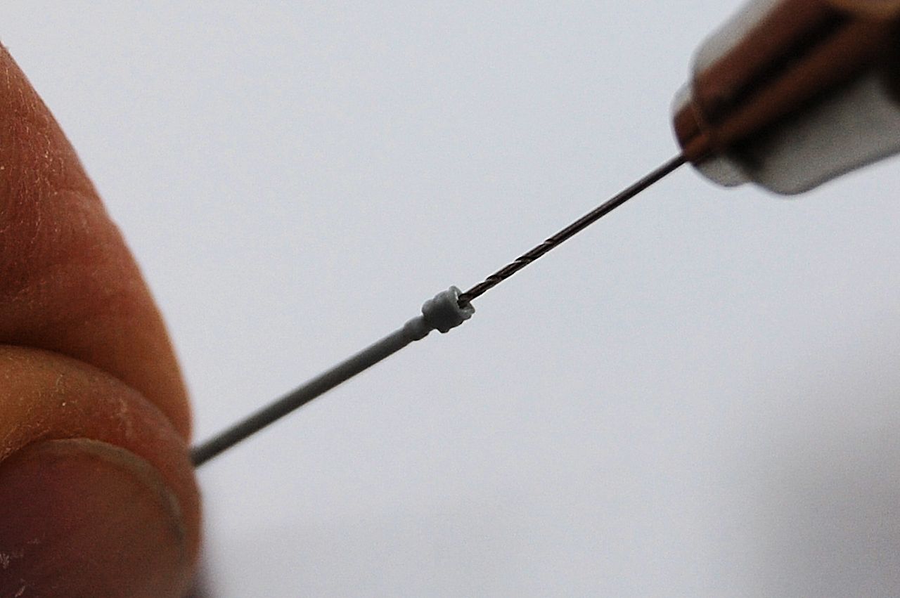
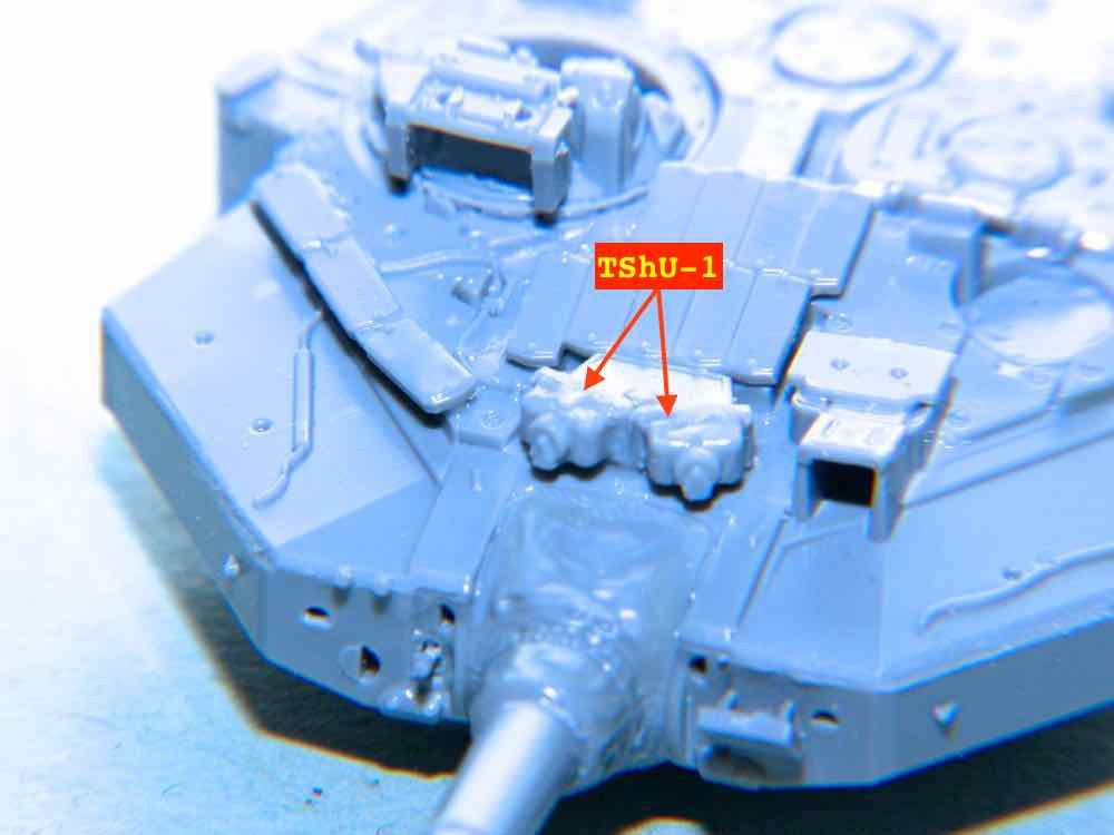
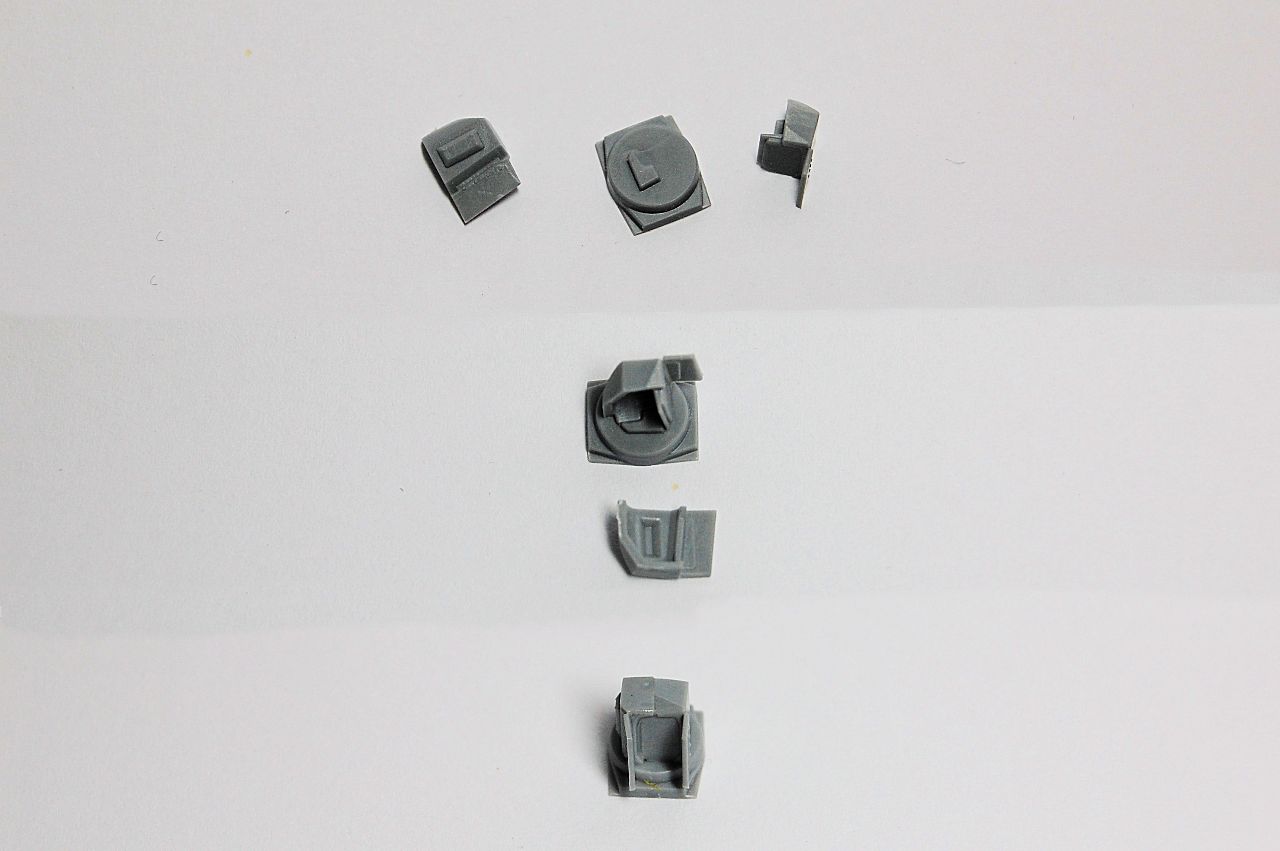
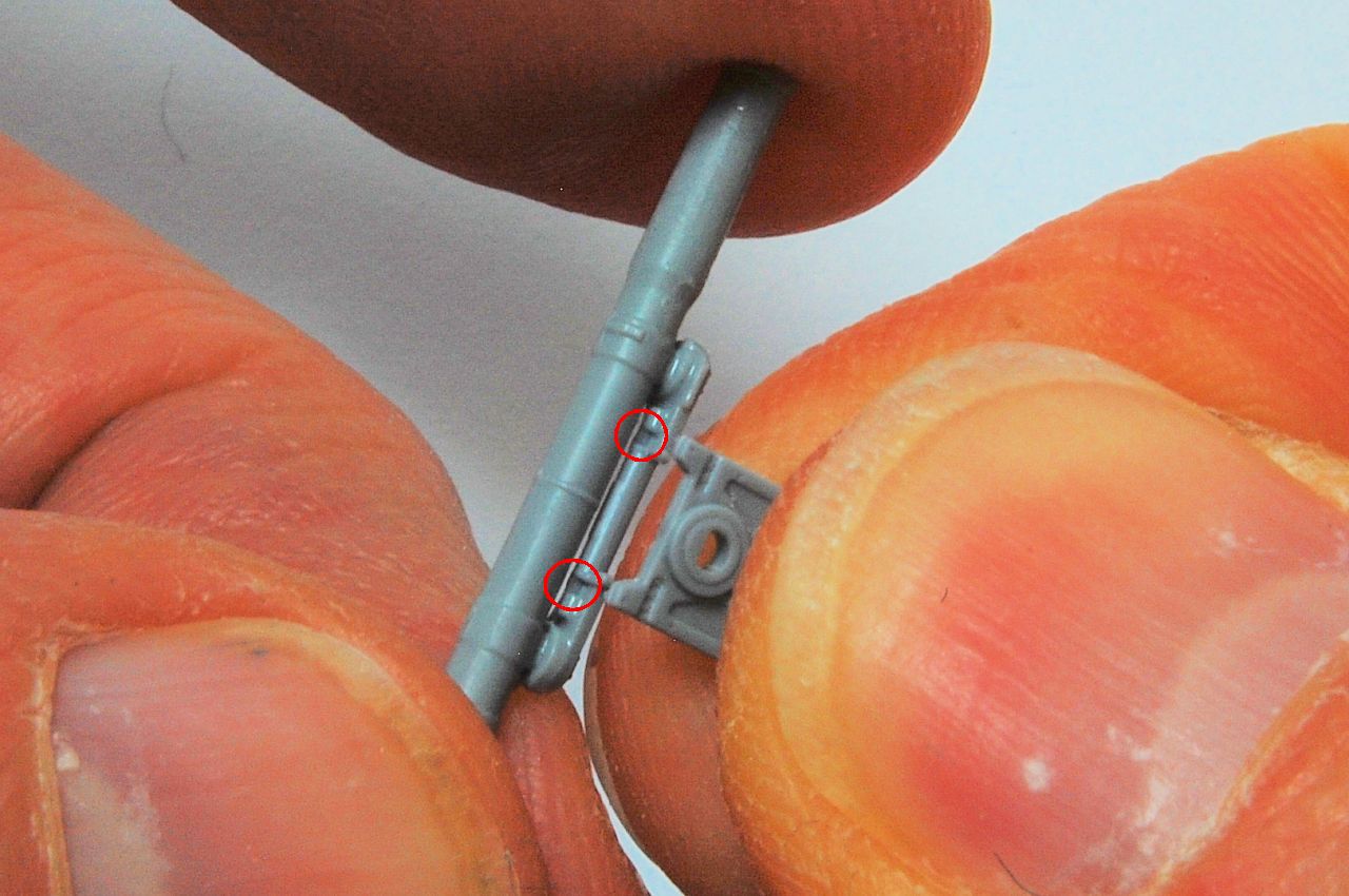
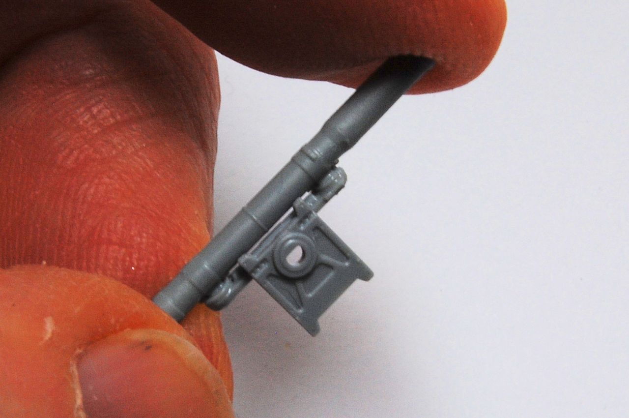
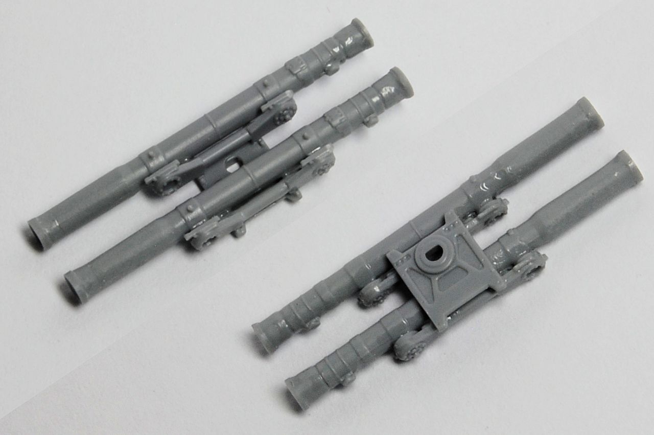
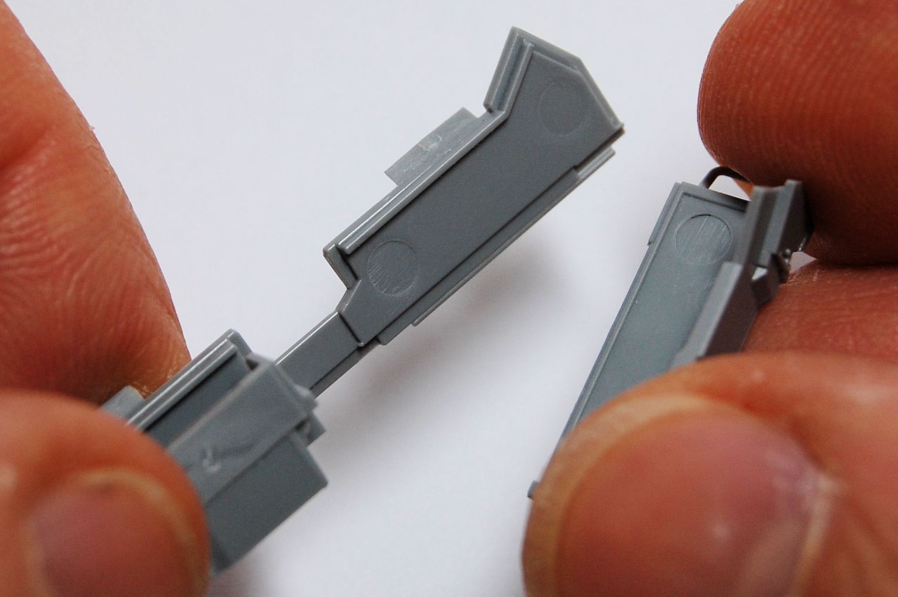
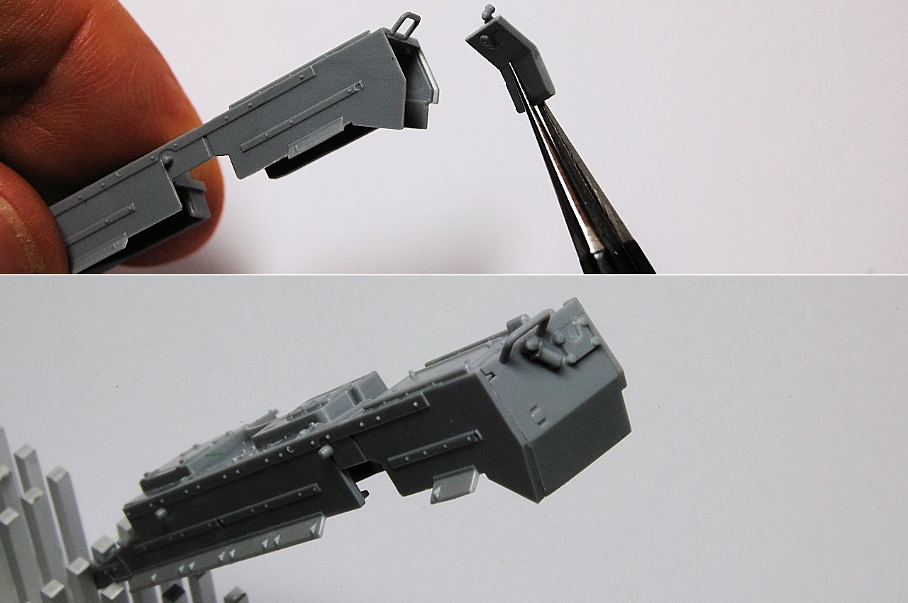
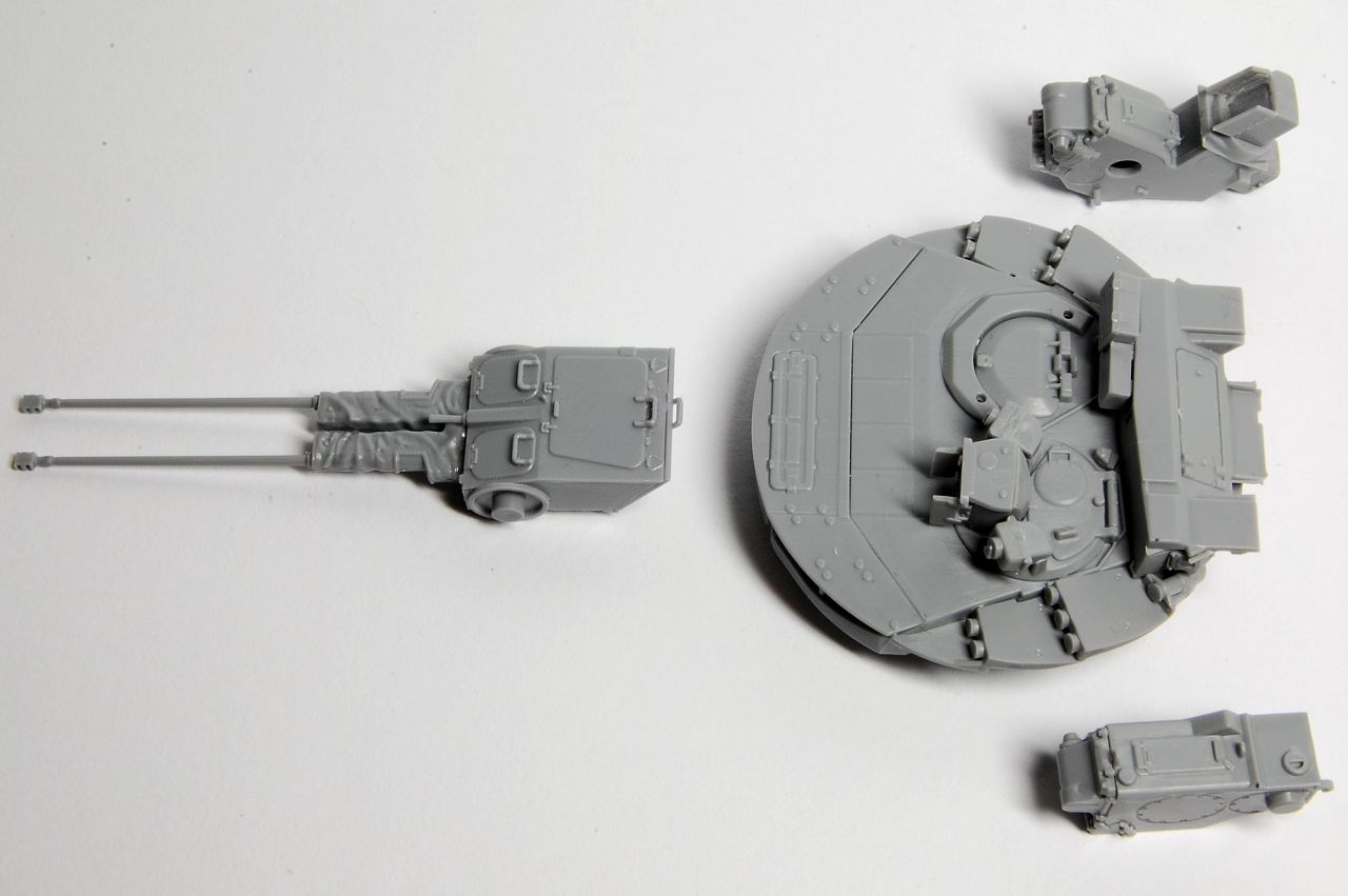
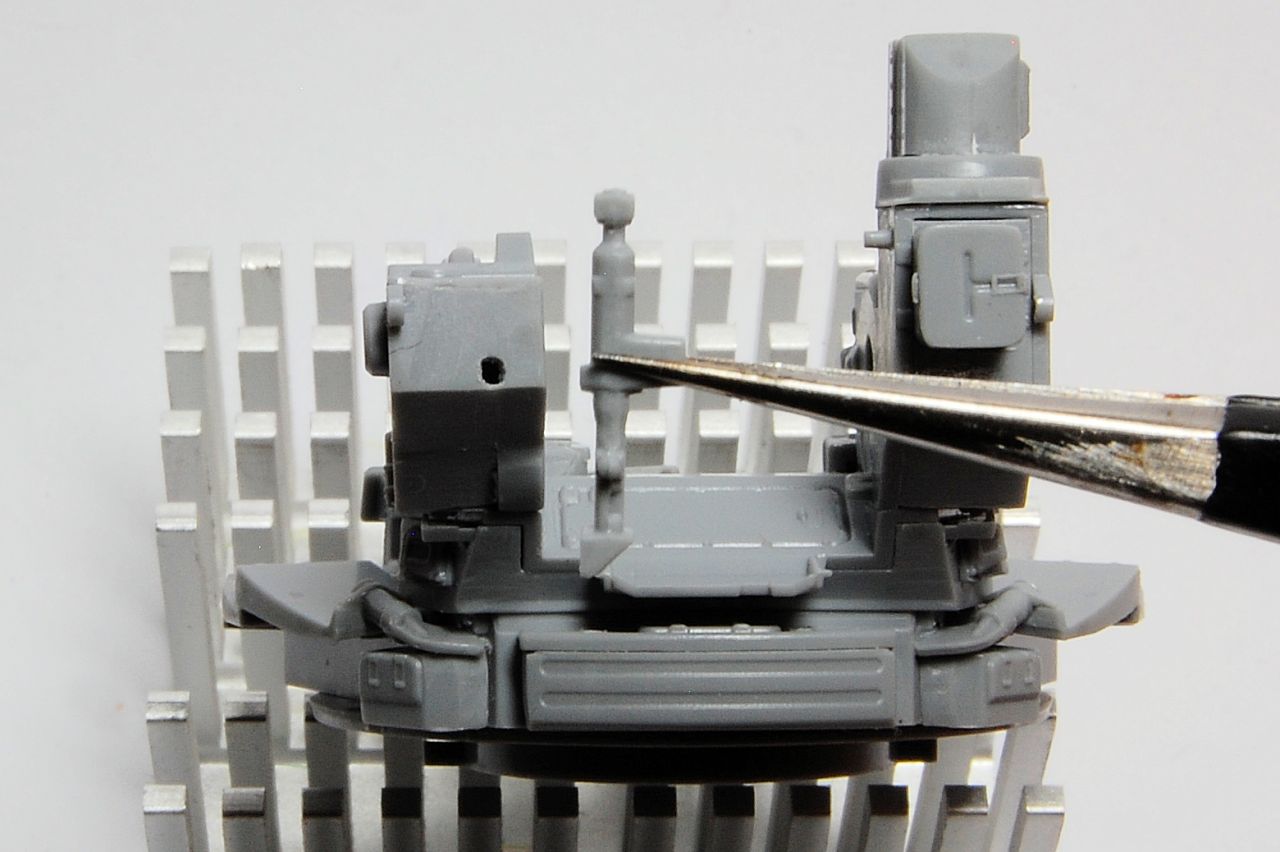
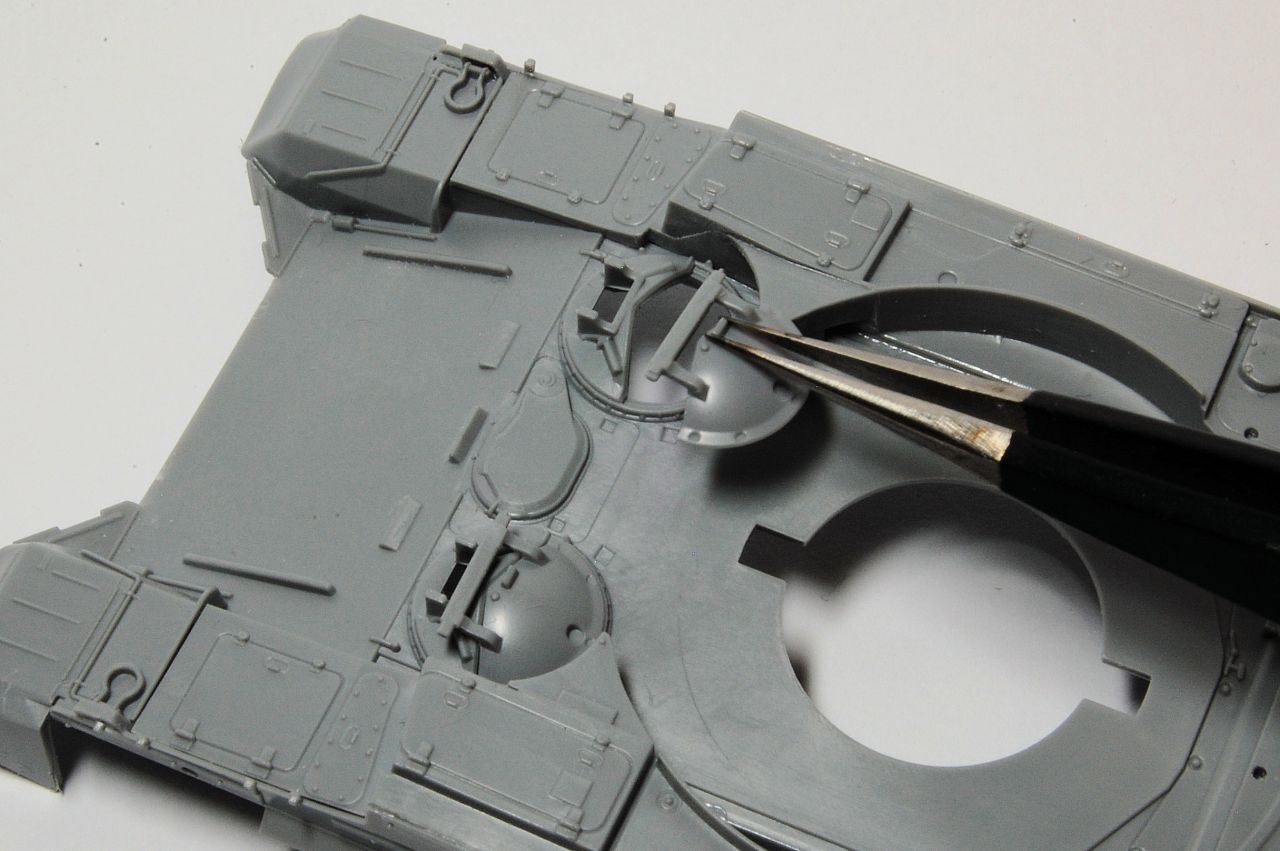
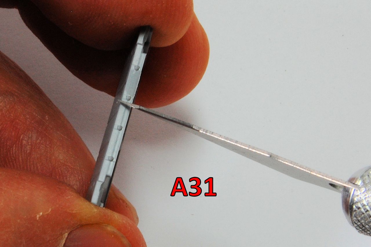
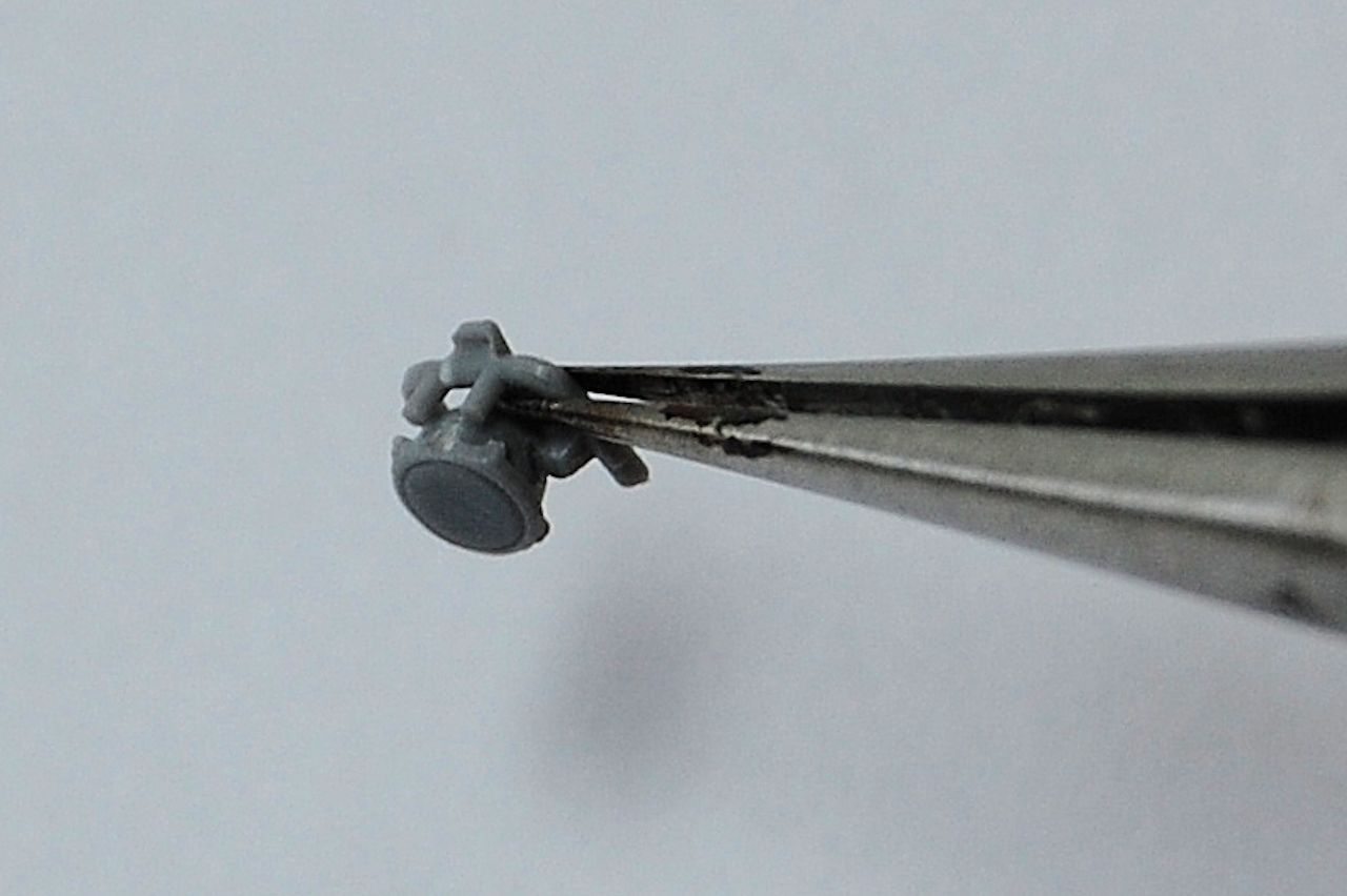
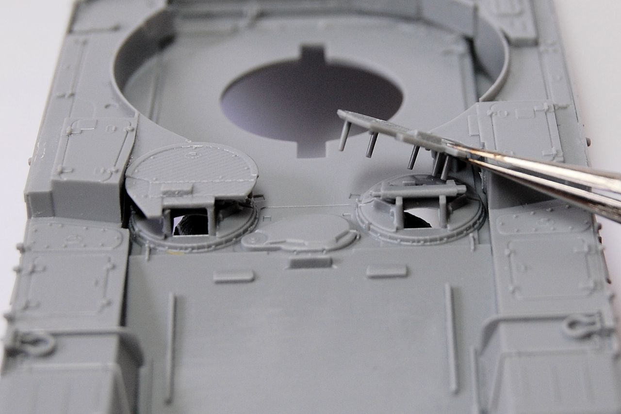
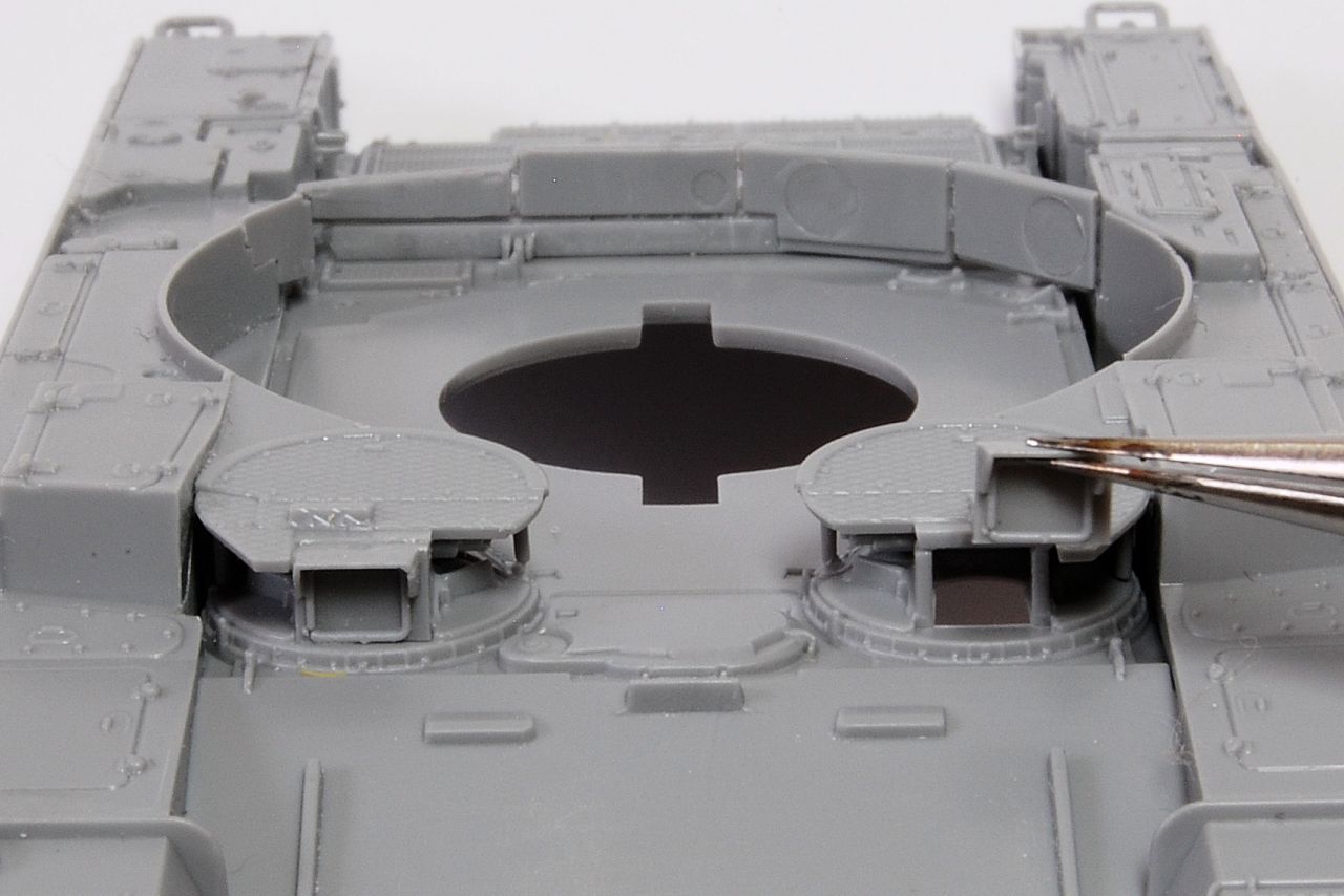
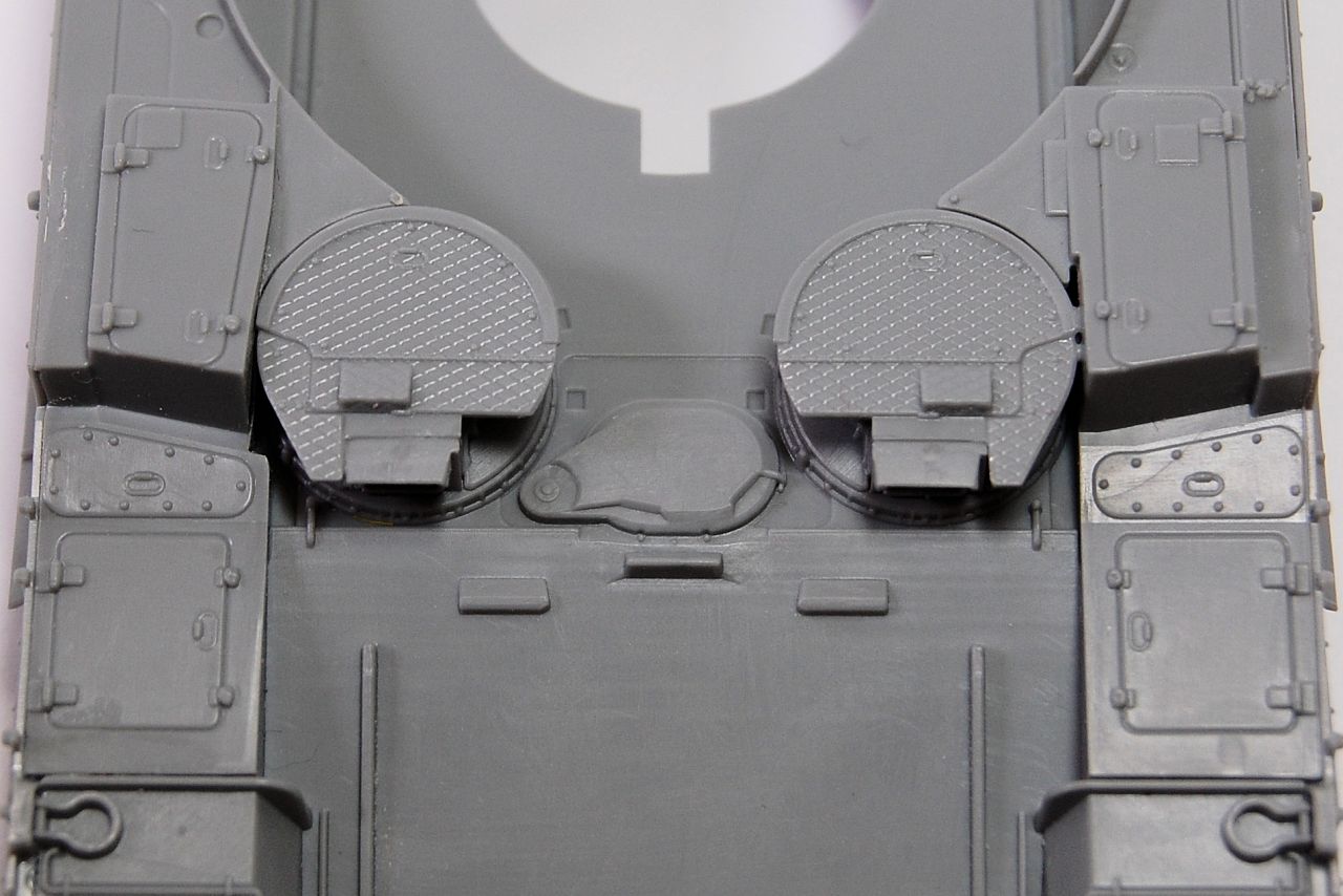
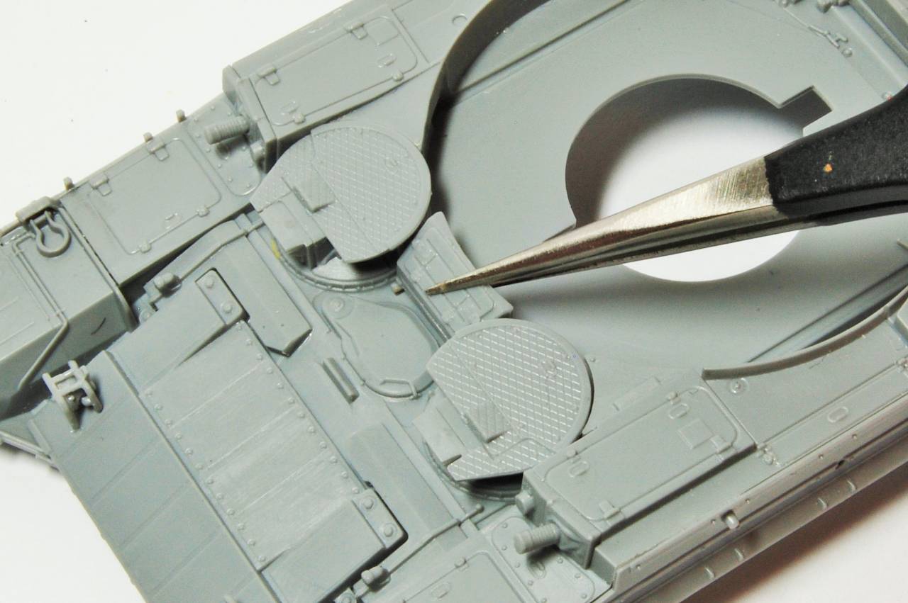
Then we get into something that may be a bit of a theme with this kit, in that when you feel like you've been dealing with a pretty small component, the next one is much smaller. These two, possibly optical devices, attach to the sides of that structure:

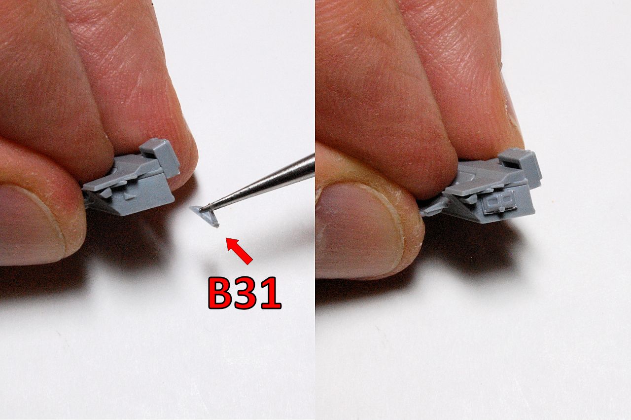
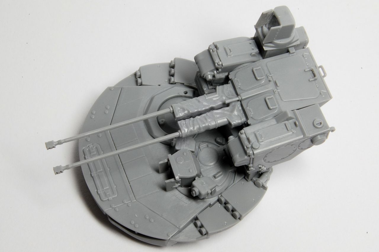
Having managed that without losing either of them, a rest is in order.
tread_geek
Visit this Community
Ontario, Canada
Joined: March 23, 2008
KitMaker: 2,847 posts
Armorama: 2,667 posts
Posted: Sunday, March 19, 2017 - 08:03 AM UTC
BRAVO, Matthew,

I'll be following this with great interest as I have the Zvesda T-90 in the building process and already I see a similarity with this kit. If this kit is like what I have experienced you are in for a very interesting time. Just remember to stay calm and carry on!

Cheers,
Jan
tread_geek
Visit this Community
Ontario, Canada
Joined: March 23, 2008
KitMaker: 2,847 posts
Armorama: 2,667 posts
Posted: Sunday, March 19, 2017 - 11:16 PM UTC
Matthew,

I typed the above using my iPad late yesterday evening and if you are wondering about the ( ) icon, I guess that my full size finger accidentally hit it on the miniature keypad. BTW, you showed me yours so I'll show you my Zvezda 1/72 kit box.


Cheers,
Jan
firstcircle
Visit this Community
England - South East, United Kingdom
Joined: November 19, 2008
KitMaker: 2,249 posts
Armorama: 2,007 posts
Posted: Monday, March 20, 2017 - 03:44 AM UTC
Don't worry Jan, I didn't notice the . From what I can see (not in your photo obvs...) the only common bits are the wheels and the lower hull, and this one looks a bit more full with two sprues on top of that.

I must admit to being slightly confused having read that this system was based on the T-72, so is the T-90 lower hull and running gear identical, or have they cheated slightly?

Anyway, on with the build:
Here we have the housing for more swivelling optical gear, built up as a shell from two halves. It's quite awkward holding this together while applying cement.

Once set the front screen of the device slides nicely into place:

Stepping away from that part while it fully cures we move to assemble one of the "cheeks" (do we still use that term?) of the two cannon, that big hole on the left is where one trunnion locates.


It fits together well, and it's possible to cement it all from the inside. Into the rear end (this bit will sit up on the back of the turret between the cannon and the rocket launchers) is inserted another kind of locker thing, which will get a door with a catch added later.

Then back to this optical device, we have a choice of protective flaps closed or open - we have to go open of course. The location of the hinges is not that definite, so a bit of adjustment is needed as the cement hardens to get the right angle. Photos of the real thing suggest they don't open wide, just point straight ahead as per the illustration:

More tiny pieces with little hinged doors on them attach to the turret rear, again it is possible to do all the cement underneath on the blind side:

Next up is an array of grenade launchers (I think) that sit in a tier around each side of the turret in a one-three-two arrangement. The front covers should be dead flat, so a small mould line needs to be eliminated from each...

...before they are attached. This is designed well and the parts fit together quite precisely, starting with the two tube part, followed by the three tube...

...with the single tube piece going on last at the back, the only one that needs a bit of careful adjustment to make them reasonably symmetrical:
celt15
Visit this Community
Wales, United Kingdom
Joined: September 16, 2016
KitMaker: 95 posts
Armorama: 91 posts
Posted: Monday, March 20, 2017 - 03:47 AM UTC
A very complex but interesting build.
firstcircle
Visit this Community
England - South East, United Kingdom
Joined: November 19, 2008
KitMaker: 2,249 posts
Armorama: 2,007 posts
Posted: Thursday, March 23, 2017 - 04:13 AM UTC
Thanks Kenneth. Next comes yet more of some kind of optical equipment, possibly cameras, two small devices that are represented with their covers on - in the real thing you can see these fold down to reveal the lenses.


Unfortunate that one sprue attachment is right on the top of each piece. They locate via one corner cut out and one leg. In between them goes the swivelling periscope assembled in step 2-a:


...and the sub-assembly from step 2B goes on the turret rear:


A rear view of the turret now looks like this:


Step 3-a starts to build up the pair of 2A42 30mm automatic cannon. These have a muzzle brake which at this scale is just represented as surface detail, and I thought about but rejected the idea of drilling them out; I did drill the ends out though:

The barrels mount with very definite precision into the two halves that are textured to simulate the fabric covers over the base unit. The two halves are only subtly different and it is worth keeping track of which is which:


When the two halves are sandwiched around the gun tubes there is a noticeable indentation at the join, so I gave it plenty of cement and will reshape it down later.


If you're interested in this gun, it has its own web page on the manufacturer's website:Tulamashzavod 2A42
There are also some very close up views of the muzzles at 2:50 on Uralvagonzavod's official Terminator video.

As well as a demo of its impact on a bus...


Knuckles
Visit this Community
Oregon, United States
Joined: March 09, 2017
KitMaker: 525 posts
Armorama: 266 posts
Posted: Thursday, March 23, 2017 - 04:30 AM UTC
I'm building this kit in 1/35 and see some of the same issues you're seeing repeated there. Especially the fabric gun cover--exact same issue, but bigger in scale. I also had some issues with the mounting of the two lasers on the sides of that hatch. Getting all of the clear parts into their spots, gluing them, and then masking was a NIGHTMARE.

It's a fine looking kit, and each portion of it was its own little build. That turret and weapons system took me longer than the running gear!

I primed it last night, and should be ready to begin the pre shading tonight.

I'll be looking forward to seeing how the tiny-T turns out!
celt15
Visit this Community
Wales, United Kingdom
Joined: September 16, 2016
KitMaker: 95 posts
Armorama: 91 posts
Posted: Thursday, March 23, 2017 - 05:12 AM UTC
I am not familiar with this AFV,but I am enjoying your build and am interested to see it progress.
tread_geek
Visit this Community
Ontario, Canada
Joined: March 23, 2008
KitMaker: 2,847 posts
Armorama: 2,667 posts
Posted: Thursday, March 23, 2017 - 07:38 PM UTC
Matthew,

And your adventure continues! The more I see of your build, the more I can discern the similarities in design and “logic” in its production between the Terminator and the T-90. As with many kits these are a “mixed bag” when it comes to ease of assembly, parts size and both simplicity and complexity!

Just for possible clarification the parts B20, B21 I believe are meant to represent the TShU-1 a laser guidance detector and part of an active ATGM defence system. Similar systems will be found on the turrets of modern Russian and Ukrainian tanks and similar “receptors/detectors” can be seen on the Zvezda T-90.


Not meaning to interfere with this thread but I am somewhat curious as to what the Terminator’s suspension looks like. I have read that the T-90’s is based on the T-72 But not totally the same. Here is the T-90 one for comparison.


I must offer my congratulations on your successful drilling out the bores on the 30 mm cannon. I have attempted this operation on the Zvezda Mi-28 Gunship cannon and appreciate how nerve wracking it can be. Thanks also for the interesting links to the Terminator videos. I will definitely see if I can’t order one from my local Zvezda retail agent. Can’t wait for the next installment.

Cheers,
Jan
firstcircle
Visit this Community
England - South East, United Kingdom
Joined: November 19, 2008
KitMaker: 2,249 posts
Armorama: 2,007 posts
Posted: Monday, March 27, 2017 - 01:18 AM UTC
Jan, thanks for the fill-in on those particular devices; I see it is also known as "Shtora" and is an electro-optical system that detects and interferes with the guidance systems of some anti-tank missiles. I might be wrong but these items in the Terminator kit look a bit more sharply defined than in your photo - or is that just your photo?

From your hull photo, I suspect that the hull is the same, and I am certain that the wheel sprues in the T-90 kit are the same as in this kit. I can't show you a picture yet though, because that'd be "getting ahead of myself" ((c) GFNewman).

The pair of gun barrels assembled in step 3-a are now built into the rest of the 2A42 unit:


The fit of this is fine, with the usual caveat when building up box sides like this, of letting the cement set enough so that it holds the parts together but they can be realigned.
Another of the many optical systems is then put together and added to the gun cheek made in step 4-a, which also receives additional parts to complete it:


That completes page one of four of the construction steps.
firstcircle
Visit this Community
England - South East, United Kingdom
Joined: November 19, 2008
KitMaker: 2,249 posts
Armorama: 2,007 posts
Posted: Monday, March 27, 2017 - 01:54 AM UTC
Page 2 starts with 6-a, the sub-assembly of one pair of the 9M120 Ataka anti-tank missile launchers. For each launcher there is a tube plus two end caps which are very tiny, so I cemented them in place and then cleaned up the attachment points. The photo shows three of the caps in place, one still on a piece of sprue. Don't mix the end caps up as each end is different.

The caps fit perfectly well, tight but not too tight, but it seems to me that the front end cap (the plain one) should have been much thinner so that the join was the ridge that is meant to be there, rather than effectively including several more scale centimetres of the tube so that you need to eliminate the join, leaving the narrow ridge at the end. You can see what I mean in this extract from the instructions:


So there's that, and there is removing the mould lines while not destroying the details on the tubes. This is all quite tedious and requires a good deal of concentration...

Parts A25 / 26 (see above) are brackets that attach to the missile tubes. These are OK to clean up, but note that they are not reversible, one end having a small additional part - small red rings on the above instruction step. These have to attach to the correct two studs on the tube (there're more than one set) and the assembly is not overly definite, so I let them set for a while, trying to ensure they were at the right angle, as this will be critical for them lining up correctly when mounted.

B49 is the plate that these are mounted on, and the attachment points are quite small, ringed in the photo below.


Put the two together to get this, which was put aside to set completely before any further tidying is done with file / emery paper etc. This is one set, a view of each side. I'm so looking forward to making the other pair...
celt15
Visit this Community
Wales, United Kingdom
Joined: September 16, 2016
KitMaker: 95 posts
Armorama: 91 posts
Posted: Tuesday, March 28, 2017 - 04:56 AM UTC
Still enthralled with this unusual vehicle.
tread_geek
Visit this Community
Ontario, Canada
Joined: March 23, 2008
KitMaker: 2,847 posts
Armorama: 2,667 posts
Posted: Tuesday, March 28, 2017 - 07:07 PM UTC

Quoted Text

... I see it is also known as "Shtora" and is an electro-optical system that detects and interferes with the guidance systems of some anti-tank missiles. I might be wrong but these items in the Terminator kit look a bit more sharply defined than in your photo - or is that just your photo?


Matthew, from my understanding and according to a local Russian equipment "expert", Shtora is the combination of several separate pieces that together make up the Shtora System. electro-optical sensors are one piece as are "jammers", computers and projector mortars (smoke dischargers?) that can launch "decoys" or even "hard kill" warheads to protect the vehicle to which they are attached. The "jammers" do not appear to be evident on the Terminator although the sensors appear to be present. And yes, the sensors on your kit do appear sharper than the T-90's.


Quoted Text

From your hull photo, I suspect that the hull is the same, and I am certain that the wheel sprues in the T-90 kit are the same as in this kit. I can't show you a picture yet though, because that'd be "getting ahead of myself" ((c) GFNewman). ...


My research is not definite on the possible Terminator suspension. A couple of sources note that later version T-72 suspension components appear similar to the same as the T-90 ones. One source strongly suggests that should T-72 components not be available that T-90 suspension ones may be used instead.

Great progress on the build and I see the missile tubes were a bit of a pain as were the ones for the Mi-28 Havoc. Zvezda kits aren't bad but each appears to a few shall we say "oddly designed" assemblies. Please keep up the good work and I can't wait to see more!

Cheers,
Jan
firstcircle
Visit this Community
England - South East, United Kingdom
Joined: November 19, 2008
KitMaker: 2,249 posts
Armorama: 2,007 posts
Posted: Wednesday, March 29, 2017 - 02:27 AM UTC
Kenneth, Jan, thanks... Jan, not 100% clear on the Shtora system - I found one source saying this does have it, and that it can automatically triggered the grenade launchers around the turret.

Anyway, having completed the second pair of missile launchers, we move to some bigger sub-assemblies, the hull sides, starting with 7-a to 7-c:


Start off with the rear lamps which, though tiny, fit into the rear track guard plate perfectly. I can see in the photo there is a bit of mould seam to clear up, easier done when attached.


This is both sides of the left track guard side (A65), with the cleaned up sprue attachment points ringed; these are on the thin edge, but what I have inset is a photo of this part as it attaches to the side skirt (B10), so you can see that the clean up is not crucial as it is hidden under the skirt.


The track guard side and top going together; the join is on the top and though the fit is good, care needs to be taken to get a good join along the whole length without any cement squeezing through to the top.


This is the inside rear part of the track guard, followed by back plate with the rear lamp on it.


Then it is a similar story with the right hand track guard:


Knuckles
Visit this Community
Oregon, United States
Joined: March 09, 2017
KitMaker: 525 posts
Armorama: 266 posts
Posted: Wednesday, March 29, 2017 - 02:41 AM UTC
I snapped both of those rear lamp guards off several times while fitting my tracks--beware my friend. I have #hamfists
firstcircle
Visit this Community
England - South East, United Kingdom
Joined: November 19, 2008
KitMaker: 2,249 posts
Armorama: 2,007 posts
Posted: Wednesday, March 29, 2017 - 02:55 AM UTC
So sprues A and B are starting to empty out and before the turret moves towards completion, here we have one more sub-assembly, the left cheek that the pair of 2A42 auto cannons are mounted on. This one is similar to, but slightly simpler than, the right hand item that we built in steps 4-a and 4, just five pieces (A68 is missing from the photo partly as I was afraid of it disappearing while I was messing around with the camera).


The curved item on the left, B8, is the armoured housing for the elevation mechanism for the missile launchers; note that it has some slight marks on the surface, but don't be tempted to smooth it all out as on the real thing this part is cast, so perhaps even some more texture could be added:


We now have the sub-assemblies ready to mount the auto cannon to the turret:


These photos are a dry run, though you can see that the fit is good enough that it holds together. The cannons sit tightly in one side cheek, but not the other, but these locate well on the turret so that they don't slide off.

Now I am thinking about how to paint this assembly. I don't think it is possible with it like this, so I think the choice is whether to assemble the cannons with the mounts, or the mounts to the turret. I think the join between the cannon unit and the side mounts is better hidden than between the mounts and the turret. Although it may not be possible to fit the cannon unit into the assembled mounts so that it elevates, and it may necessitate shaving off the locating trunnions, I think it will be cleaner to construct and easier to paint this way.


firstcircle
Visit this Community
England - South East, United Kingdom
Joined: November 19, 2008
KitMaker: 2,249 posts
Armorama: 2,007 posts
Posted: Wednesday, March 29, 2017 - 03:01 AM UTC

Quoted Text

I snapped both of those rear lamp guards off several times while fitting my tracks--beware my friend. I have #hamfists


Christian, thanks for the warning, I can see this happening somewhere around step 12 as the whole thing flips over. However the tracks are assembled to the lower hull first then the topside and lower joined... not sure if that's the same? Anyway, I'll take care.

I did notice last night that one idler axle pin is not on the hull lower, but is in the bag.
Knuckles
Visit this Community
Oregon, United States
Joined: March 09, 2017
KitMaker: 525 posts
Armorama: 266 posts
Posted: Wednesday, March 29, 2017 - 03:01 AM UTC
Really nice.

Have you decided on a color?
firstcircle
Visit this Community
England - South East, United Kingdom
Joined: November 19, 2008
KitMaker: 2,249 posts
Armorama: 2,007 posts
Posted: Wednesday, March 29, 2017 - 03:13 AM UTC

Quoted Text

Have you decided on a color?


I quite like the splinter camo that I've seen it in, and then I found this on eBay, so I've already taken delivery. No idea how easy they will be to use, but I suspect it will be a start, and it does hint that you may need to back it up with some of your own masking tape.
Knuckles
Visit this Community
Oregon, United States
Joined: March 09, 2017
KitMaker: 525 posts
Armorama: 266 posts
Posted: Wednesday, March 29, 2017 - 03:27 AM UTC
Beauty! Let us know how those work out. I've got mine going into an arctic scheme, white base, grey, and then black. Like this (kind of), but I'll be freehanding it or making custom stencils:
firstcircle
Visit this Community
England - South East, United Kingdom
Joined: November 19, 2008
KitMaker: 2,249 posts
Armorama: 2,007 posts
Posted: Monday, April 17, 2017 - 12:27 AM UTC
Following an Easter break in Wales the build resumes.

Decided that I would attach the 30mm cannon mounts to the turret now and work out a way to slot the cannon in later.


Some kind of device attaches to the top left rear plate by a single hole which had to be enlarged considerably:


The turret is mostly finished for now, so putting that aside to set, attention turns to the upper hull:

A few sprue attachment points to be cleaned up:


Then we can add the hull sides that were put together in sub steps 7-b and 7-d. These fit on really well; first the right side:


Followed by the left - this assembly flexes at about 3/4 towards the rear, and I attached that last 1/4 first (ringed) then cemented the rest from underneath:


Then we're adding nice details to the hull top. Engine deck cover (A1) and rear cooling vent (B47)


Crew hull hatches / visors; these are quite complex, with a domed rear facing hatch going on first, more to be added later:


Putting that to one side, we prepare the nose armour (A31), removing the mould seams which will otherwise be visible at the very front:


Before attaching that to the hull, the front lamps have to be part built up, back to some very small parts and quite fiddly construction. As usual with the assembly of several tiny parts that all have to align with each other to get the correct shape, it can be difficult getting the cement in the right place. On reflection I wonder if it would be better to attach the bracket to the nose armour (A31) first, then add the lamp itself, and then the front hoop; might be easier to make sure the lamp is pointing in the right direction and is in the centre of the hoops.


The nose lower plate is a nice moulding with which needs to be handled with care to avoid damage. Here the two towing eyes are being attached:


nikon1
Visit this Community
Kansas, United States
Joined: April 11, 2005
KitMaker: 622 posts
Armorama: 605 posts
Posted: Monday, April 17, 2017 - 05:46 AM UTC
The build is coming along nicely. It appears there are some small fiddly parts to this kit. Keep us posted.
Cheers
Charlie
spacewolfdad
Visit this Community
England - West Midlands, United Kingdom
Joined: May 23, 2010
KitMaker: 642 posts
Armorama: 593 posts
Posted: Monday, April 17, 2017 - 04:23 PM UTC
Hello Matthew,

Just gone through the whole of the blog and I have to say you are making a superb job of this very complicated model. For a 1/72 kit it has a large part count and seems to require the modeller to grow an extra arm at times. You have done a lot so far, how much is left to go? I shall follow further updates with interest, well done so far.

All the best,

Paul
tread_geek
Visit this Community
Ontario, Canada
Joined: March 23, 2008
KitMaker: 2,847 posts
Armorama: 2,667 posts
Posted: Monday, April 17, 2017 - 07:08 PM UTC
Matthew,

Delighted to see this beast progressing. Zvezda appears to have come yup with a winning combination with these newer, non-quickbuilt kits. As with the T-90 I see they still have some room for their design/assembly process' to improve but you get quite a kit for a fair price. From what your pictures show, the fine detail on this kit is an improvement and noticeably better than the T-90 kit was. Beautiful progress so far and wait with "baited breath" for the next instalment. BTW, still waiting for word from my local Zvezda distributor if and when the kit may be available in my area.

Cheers,
Jan
firstcircle
Visit this Community
England - South East, United Kingdom
Joined: November 19, 2008
KitMaker: 2,249 posts
Armorama: 2,007 posts
Posted: Tuesday, April 18, 2017 - 04:04 AM UTC
Charles, appreciated, I will keep going until the construction is complete, all being well, within a week or so.
Paul, currently we're half way through page 3 of 4 of build steps, so we're a fair way through.
Jan, I agree, and it does have to be said that this is a pretty nice kit, with a good amount of well fitting and finely moulded detail.

Moving forward on to step 8, there are some sections of spaced armour plates that fit around the rear of the turret. Again, these fit well, including a kind of hinged section between the centre plates meshing together acceptably. There are some ejector pin marks on the turret side, but I am confident that these will be hidden by the turret and an additional horizontal plate that will be added later.


As noted earlier, there are more parts to be added to the hull crew hatches / visors. These treadplate textured plates are added over the domed hatches on vertical supports.

For some reason one or two of the supports of the left hand component were a little too short to fully engage with the locating indents on the hatch ring (so on the right as we view from the rear, arrowed). To try to fix this the lazy way I just gave it more cement.


Next are the lens units of the periscopes / vision devices.


Then we add two items that are built up as a subassembly in 8-a and 8-b, that swivel and are mounted in what appear to be fabric covers. Both are moulded with plain fronts, though photos show some ring details on the ends, which I will look at more closely later...

In the above photo you will see that the big front section of reactive armour, with the headlamps has also been attached. Two raised bars are moulded to the hull front to allow this section to be cemented in place with glue only needing to be applied underneath, so there is no need to apply it around the edges and risk it leaking on to the flat plates.
Here two additional L shaped sections are being added, and again, these fit very well, and it is possible to fix them in place without too much cement:


Stepping back to step 7, this structure between the crew hatches with a hinged cover is added, it's just a single item and completes that page of the instructions.

With the addition of that part, section 8 is complete, as is the upper hull for now; next is the lower hull, and wheels.

 _GOTOTOP