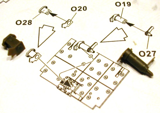
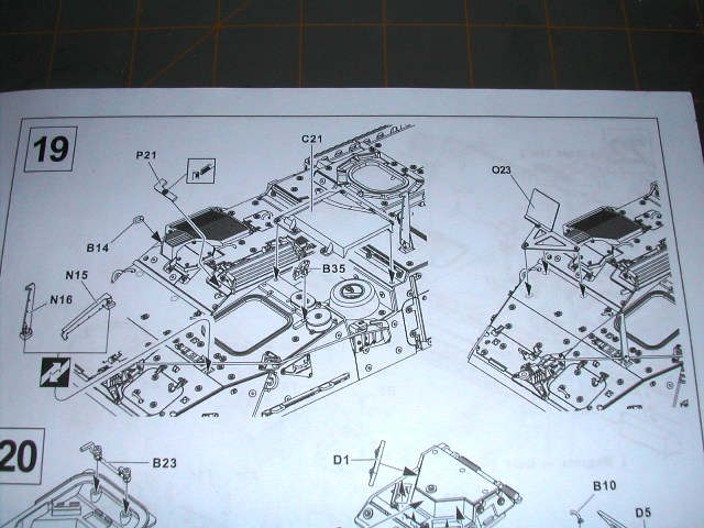
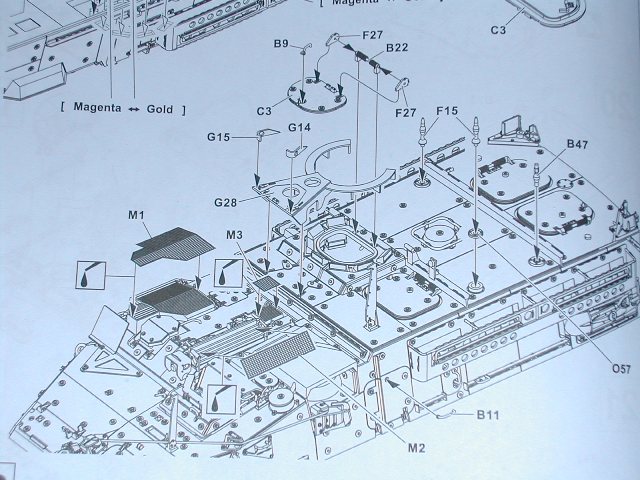
STEP 18:
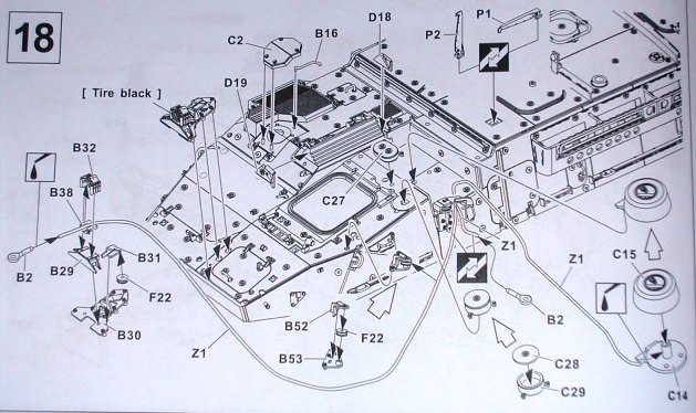
This step focuses mainly on front, upper hull details. The most significant assembly in this step is the winch drum and the corresponding winch cable guides. I had problems with many parts being brittle. I had the following parts break on me and had to scavenge them from another AFV Club kit: B16, B32, and D19. You get the choice also of having the winch cable run the full length of the front end or it can hang out just a little bit from the winch cable drum.
Here is my recommendation for the order of part installation on this step.
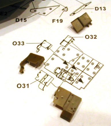
1. Parts C28/C29 (makes a sub-assembly), C27, D18, D19 and P2. You can install these parts in any order.
2. Parts B52/B53/F22 (makes a sub-assembly). Install on the upper hull accordingly.
3.B16 (remember to make the back end of this part not touch the upper hull)
4. C2
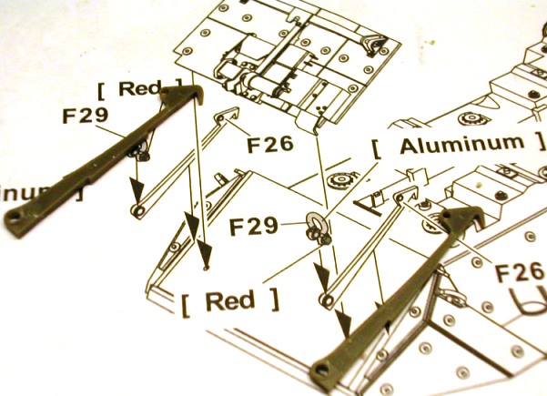
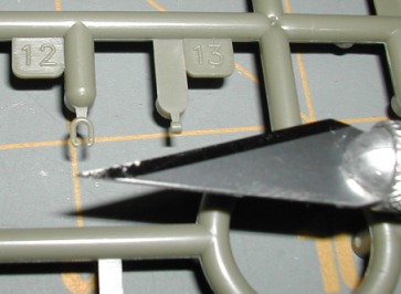
5. B30/B29/F22/B31/B38/B32 (front winch cable guide assembly). Be careful with B32 here. I had two of these break on me.
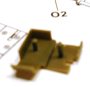
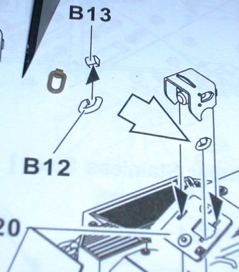
6. Glue thread (winch cable) to part B2
7. Install part C14 on upper hull. Leave part C15 off until the end of this step after you have tightened up the winch cable.
8. Take the loose end (end without part B2 attached) of the winch cable, run it through the front winch cable guide, around the winch cable guide assemblies and then back to the winch drum (C14).
9. Remove slack/excess winch cable by wrapping excess around center post on C14. Super glue 'wrapped' winch cable into place.
10. Install part C15.
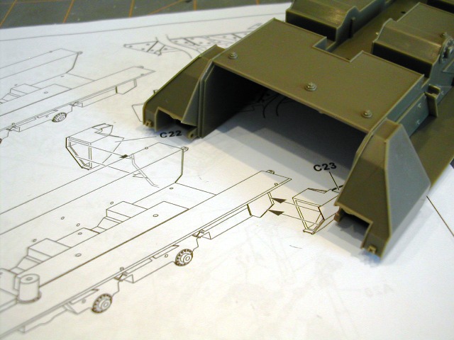
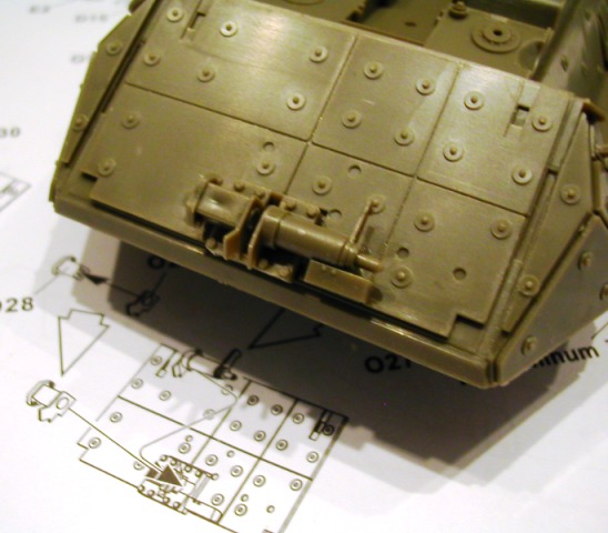
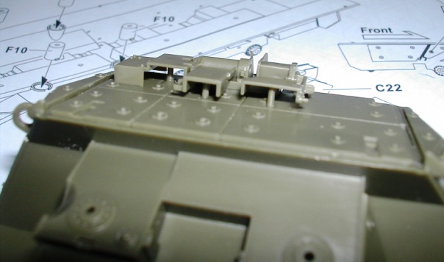
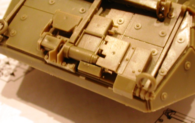
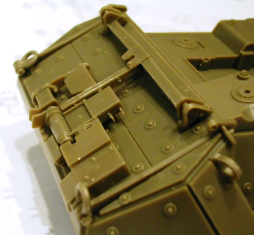
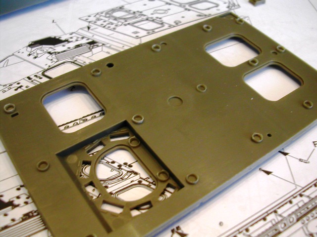
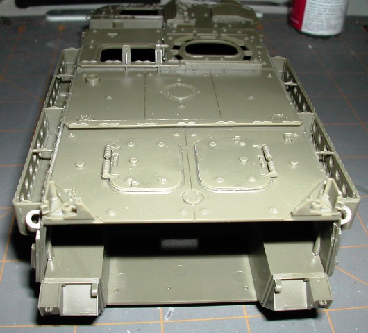
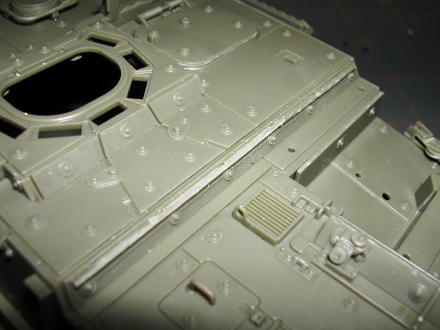
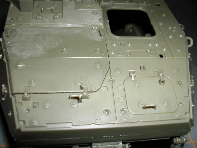
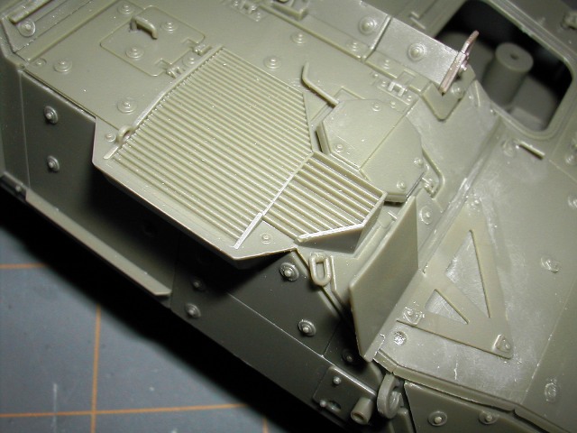
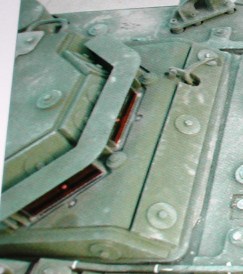
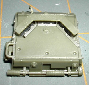
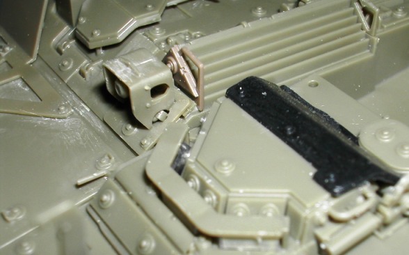
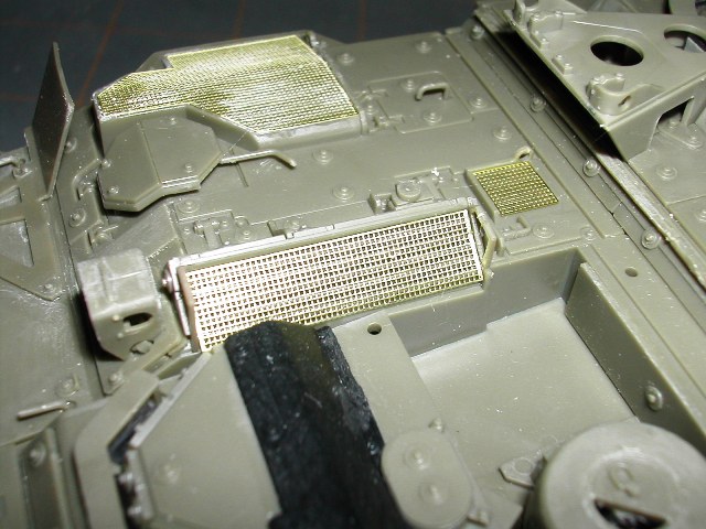
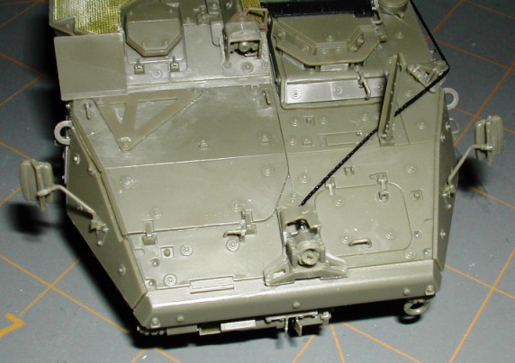
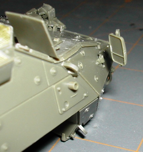
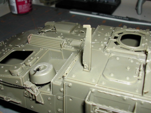
This first photo shows you parts D18 and D19 in place. You will see that part D19 is a different color than the rest of the kit. That is a result of it being a replacement part scavenged from another kit. There must be some variance in the color of the plastic from one molding run to the next.
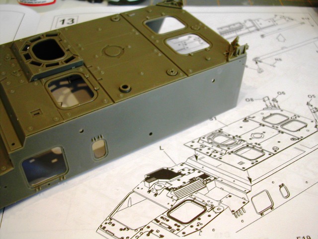
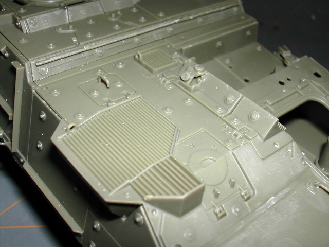
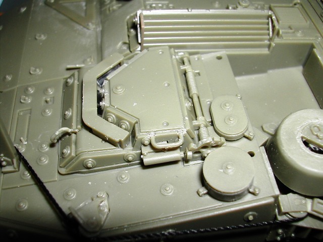
Back by the air intake/exhaust vent you see parts C2 and B16 in place. You must install part B16 before installing part C2. The reason for this is that the install hole for B16 actually sits under C2 after C2 is installed. You don't have enough clearance to get B16 in place under C2 if you try to put it on after C2 is in place. I learned this the hard way.

B16 must be installed carefully. It isn't visible in the kit instructions but the end of B16 does not touch the upper hull. The only part of B16 that touches the kit is the end that gets installed under C2. I figured this detail out after studying photos in the Stryker books by Ralph Zwilling again.
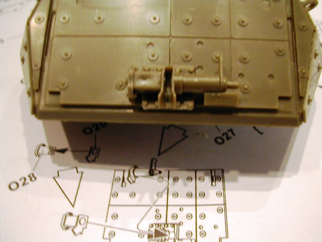
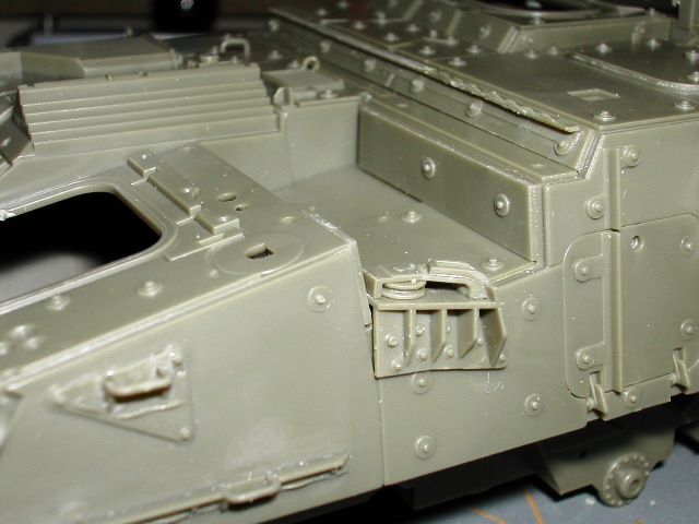
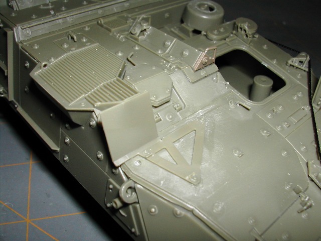
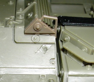
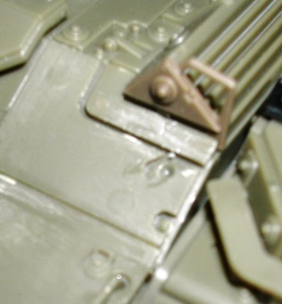
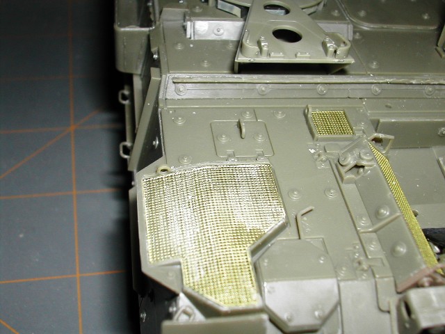
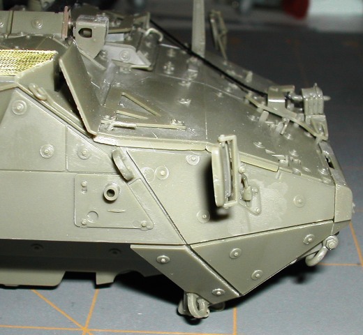
The next photo shows part P2 (wire cutter) in place. You have the option of using part P1 (wire cutter folded down) or P2 (wire cutter extended).
To the left of the winch drum, you can see parts C28/C29 and C27 installed. In the background is another angle of parts D18, D19, C2 and B16 installed.
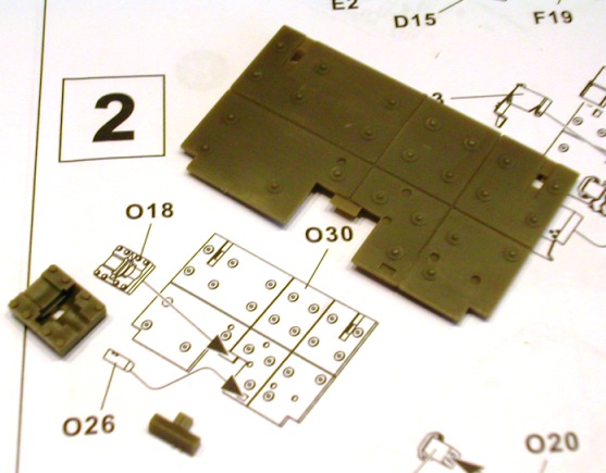
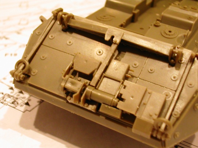
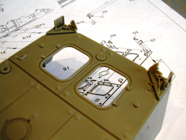
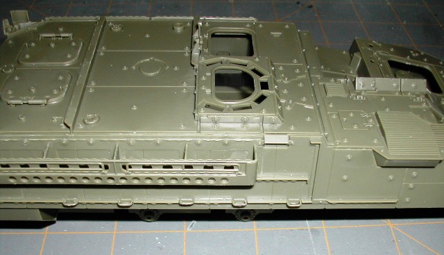
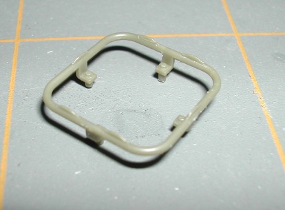
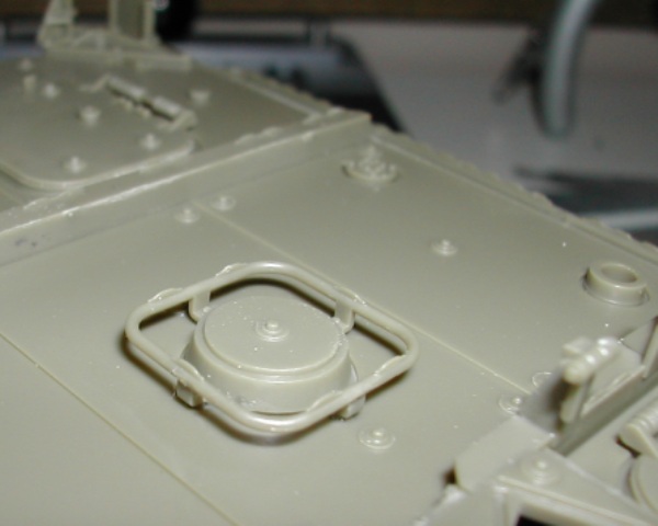
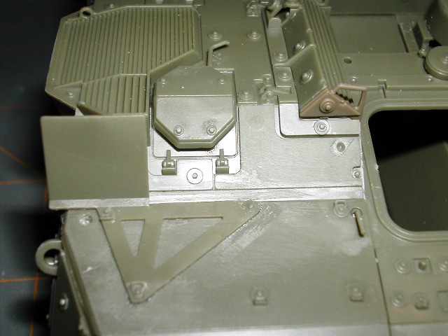
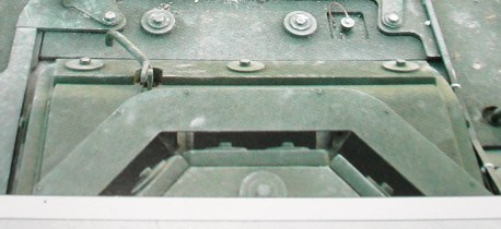
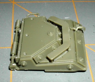
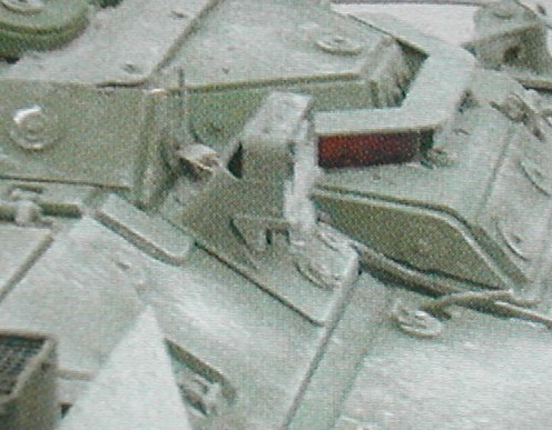
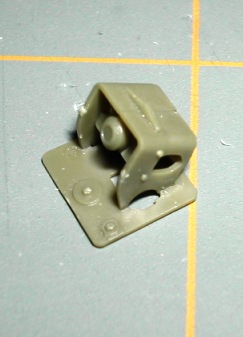
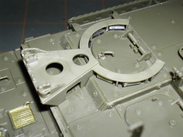
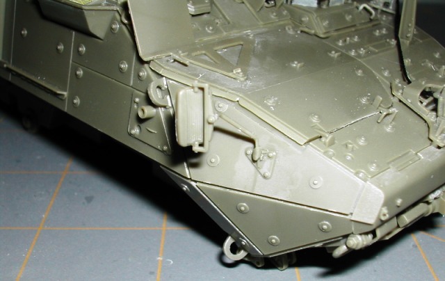
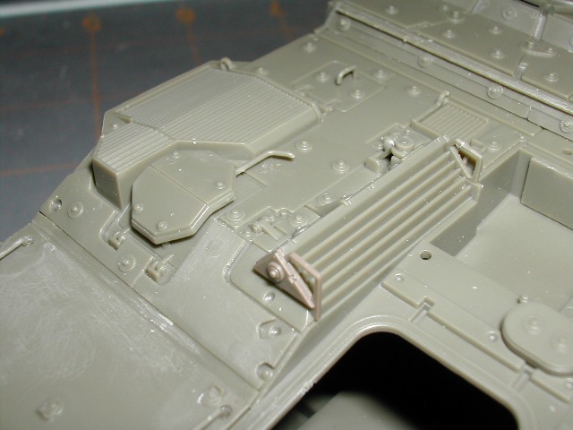
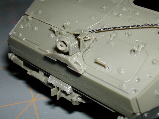
In this next image, you get a close up of B52, B53, F22 (winch cable guide assembly) installed on the upper hull. To the right is another view of C28/C29 and C27 installed on the upper hull. To the left of the screen, you can see part of the front winch cable guide assembly.
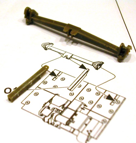
I'm going to spend a few minutes sharing some words of wisdom regarding the assembly of the winch drum (parts C14, C15 and thread) and the assembly of the front winch cable guide houseing (parts B2, B29, B30, B31, B32, B38 and F22). The assembly steps listed at the beginning of this Step 18 post were determined as a result of me making some mistakes.
One of the first things I did in this step, per the instructions, was to glue my thread (winch cable) to part C14 (ran the thread up through a hole in the bottom of C14). I then glued C15 to the top of C14 and then glued the winch drum sub-assembly into place on the upper hull. I then ran the loose end of my thread (winch cable) up through the winch cable guides on the hull side up to and through the front winch cable guide housing. After doing this, I realized how much thread (winch cable) was left over.
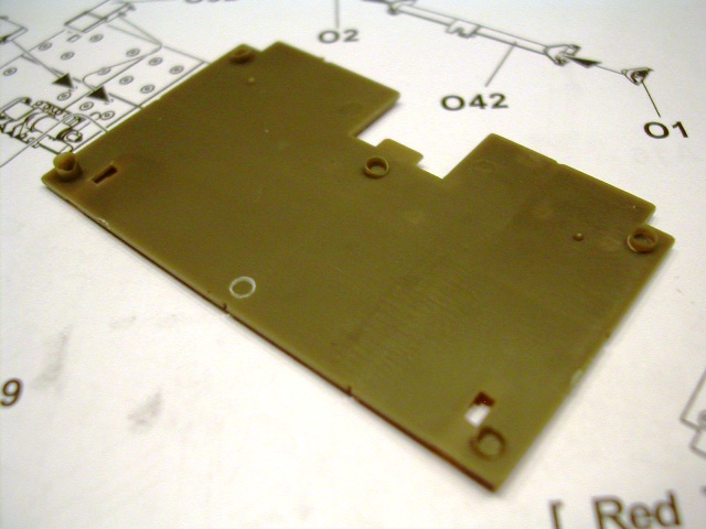
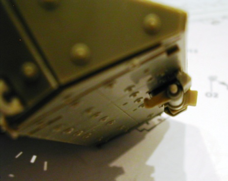
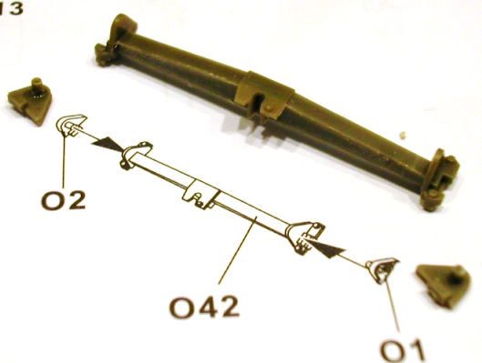
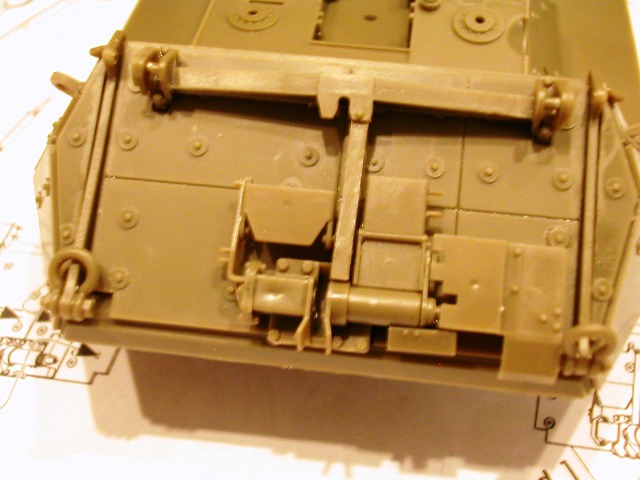
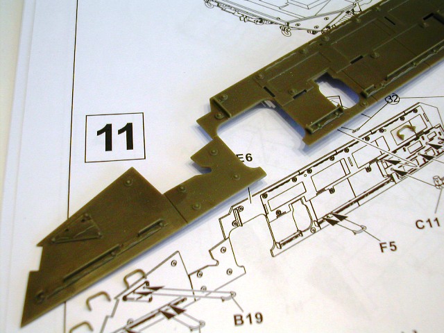
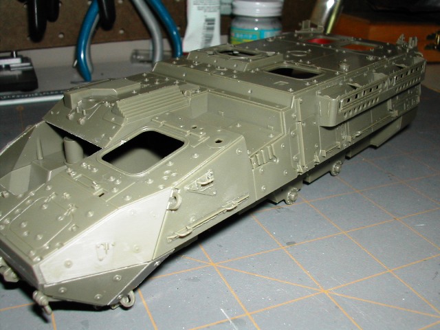
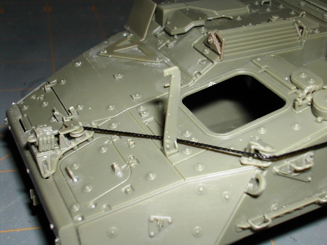
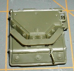
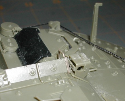
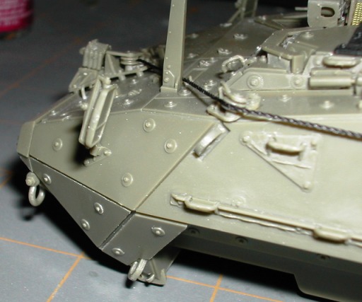
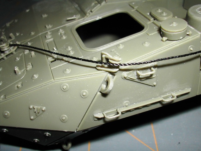
Here is a photo that shows the length of the 'winch cable' with the way I had it installed.
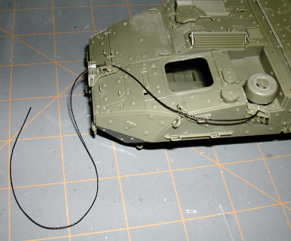
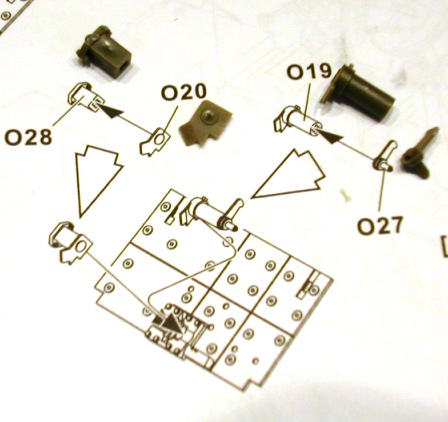
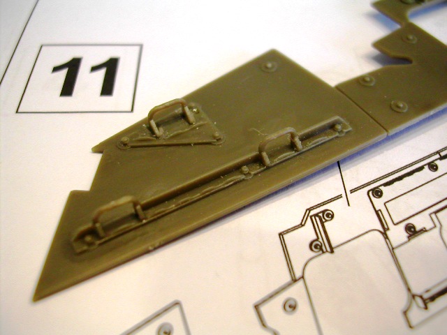
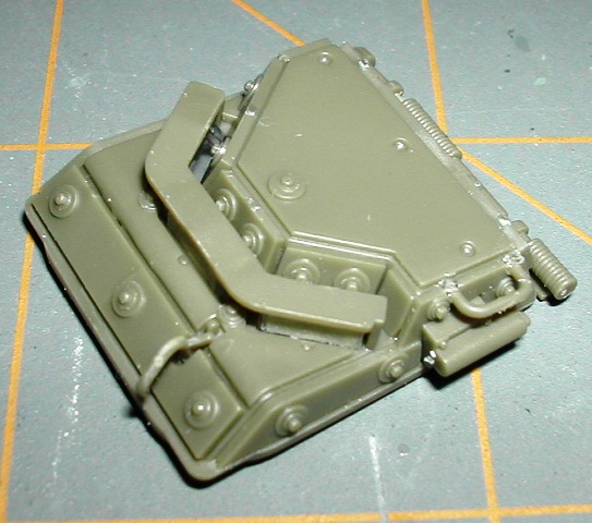
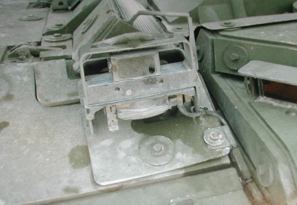
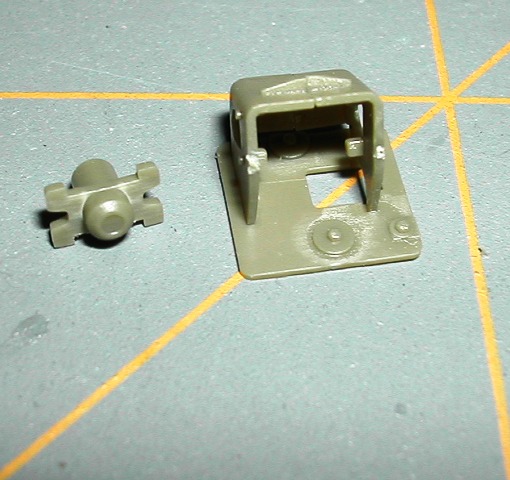
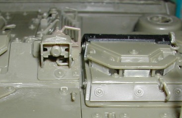
I quickly realized this wasn't going to work the way I assembled it because it leaves to much excess thread with no way to shorten/tighten it. Well, to fix this problem, I had to cut the thread at the bottom of part C14/C15 so that I could pull all the excess back through the front winch cable guide housing until the tow clevis stopped tight in the front winch cable housing...See pic below.
Once the excess was mostly pulled back, I ran the thread up through another hole in the bottom of C14/C15. After all of the winch guide sub-assemblies have had time to dry, I will pull the remainder of the excess thread tight out of the top of C15 (hence the small end sticking out) and shorten/glue in place accordingly.
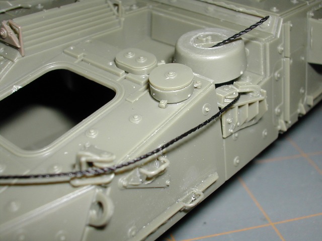
I am keeping all of the excess thread tucked into the winch drum until I'm ready to do the final 'pull tight' and glue the thread into place.
If you follow the steps I listed above, you will avoid the problems that I have had to deal with.