

Hi Mike
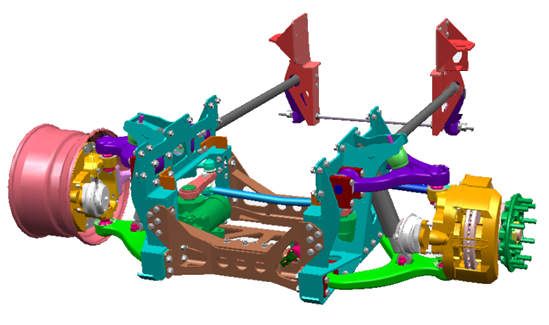
The images above are very interesting - will be fun to see how you decide to resolve the rear steering - it looks like the truck would essentially include three front suspension/steering modules - with one up front and two in the rear (but flipped back and forth). I can't remember if you purchased two kits or not...I've scratch built TAK 4 suspension modules for a MAXX Pro conversion - not exactly the same, but I'm sure a guy with your skills can tackle it if needed!
The steering mechanism for the rear will be interesting to see too - wow - lots of good stuff. Looks like there's a bracket (in blue in the diagram) between the frame rails supporting the mechanism...sorry to be stating the obvious - just a very interesting challenge.
I'm sure it will be fun to see in any case! You know....now that you're no longer making leaf spring packs...who knows what you'll tackle next!?!
Looking forward to this -
Cheers
Nick
Edit: the suspension modules I built, and noted above are the Axletech International 5,000, which while similar to the TAK 4 are not the same - each unit has two coil springs. You can see them on page 4 of a build I did a few years ago called 1/35 truck fabrication shop, on the dio forum. In any case, I'm looking forward to your solution!
Armor/AFV
For discussions on tanks, artillery, jeeps, etc.
For discussions on tanks, artillery, jeeps, etc.
Hosted by Darren Baker, Mario Matijasic
Mk23 MTVR & 16.6 ton LHS

Stickframe

#362

Joined: December 01, 2013
KitMaker: 1,661 posts
Armorama: 1,202 posts

Posted: Saturday, November 12, 2016 - 06:38 AM UTC
165thspc

#521
Joined: April 13, 2011
KitMaker: 9,465 posts
Armorama: 8,695 posts
Posted: Saturday, November 12, 2016 - 09:46 PM UTC
Nick let me first say that to have you be willing to even comment on my work is an honor! Your scratch work is nothing short of amazing! Thank you.
Setting that aside for a moment . . . . I continue to be more than a bit impressed/amazed/questioning of the TAK-4 suspension design being based on every axle having a potentially steerable spindle/king post/hub. (Whatever you want to call that.) To create a fixed, non-steering axle they just add a fixed, non-moving connecting rod to the assembly. To reverse that idea this design allows them to add a steering mechanism when necessary and create a movable axle. (I don't mean in the field but in the design office.)
Given that, I don't see the great problem with converting/creating the needed steering axles on the plastic model. The Mk23 rear axle design allows for the addition of steering gearboxes, pitman arms and drag links to turn them into steerable axles.
Is there a problem with this that I am not seeing?
To build the 16.5 ton LHS I will need one extra non-steering axle and a total of four steering gear boxes. Buying two kits, though pricey, I think will accomplish this.
(I'm gonna miss those leaf spring packs - also you're way better at coil springs than me.)

Stickframe
#362
Joined: December 01, 2013
KitMaker: 1,661 posts
Armorama: 1,202 posts
Posted: Saturday, November 12, 2016 - 11:00 PM UTC
Hi Mike -
I'm sure you're already several steps ahead of me on this! I was curious tho about how you might choose to proceed!
Yes - the module suspension is something pretty cool. From your diagram, it appears that the rear (axle) is the same as the front - just inverted - coil springs facing rearward on the back unit. Next, I suppose (axle) 3 will, as you indicated, be a conversion of the typical module from non-steer to steer. I've got to hand it to the design team for creativity - as you point out, not only does it appear that each module can be made to steer, but it also appears that they can face two different direction - differential input shaft and all!
As for the steering, I'm guessing you are indeed right, with two kits you ought to have plenty of parts - but might need to fab up a carrier - which ought to be interesting in that it will need to direct two opposing axles - I say cool! and look forward to your next update -
Keep building -
Nick
165thspc
#521
Joined: April 13, 2011
KitMaker: 9,465 posts
Armorama: 8,695 posts
Posted: Saturday, November 12, 2016 - 11:15 PM UTC
Yes it looks like they can face either way, be powered or unpowered, steering or non- steering OR EVEN . . . .
Coil spring or torsion bar!
Coil spring or torsion bar!


Thirian24
Joined: September 30, 2015
KitMaker: 2,493 posts
Armorama: 2,344 posts
Posted: Saturday, November 12, 2016 - 11:29 PM UTC
Michael,
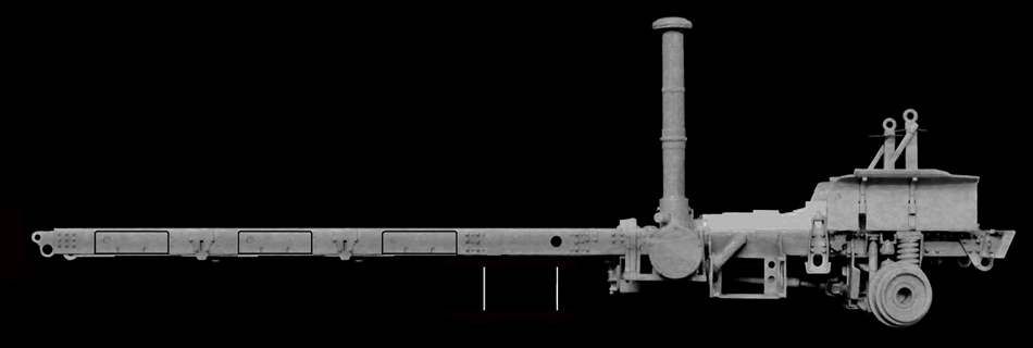
All independent suspension/axle assemblies can be made to turn. When they are setup as a "rear end" non-turnable assembly, they are then limited by a radius rod.
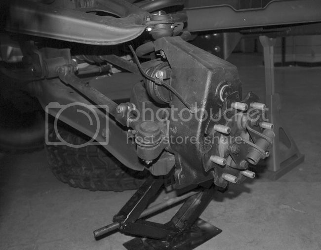
Here is an example from a HMMWV. You can see that the hubs are the same as the ones used on the front, except they use the radius rod to keep it in place and therefore it can't turn. That radius rod is also how they set the alignment "toe in/out" on the rear.
Not to imply that you don't already know this though.
All independent suspension/axle assemblies can be made to turn. When they are setup as a "rear end" non-turnable assembly, they are then limited by a radius rod.
Here is an example from a HMMWV. You can see that the hubs are the same as the ones used on the front, except they use the radius rod to keep it in place and therefore it can't turn. That radius rod is also how they set the alignment "toe in/out" on the rear.
Not to imply that you don't already know this though.

165thspc
#521
Joined: April 13, 2011
KitMaker: 9,465 posts
Armorama: 8,695 posts
Posted: Saturday, November 12, 2016 - 11:56 PM UTC
Well I did know that, including the point about adjusting the rear alignment, however, for instance on a Formula One race car, the non-steering rear spindles connect to the A-arms with a four point connection. (Like the rear axles on a MA3-537.) Therefore the rear spindles cannot be made to steer but I would think this four point connection would be stronger and more durable so I have spent some time wondering why Oshkosh/Pierce went with a two point connect on all axles?
Perhaps interchangeability of parts and reducing inventory is/was a more important consideration to the military?
CORRECTION - SOME Formula One cars have a four point connected independent rear suspension. Most have a non-steering three point connection.
Perhaps interchangeability of parts and reducing inventory is/was a more important consideration to the military?
CORRECTION - SOME Formula One cars have a four point connected independent rear suspension. Most have a non-steering three point connection.
165thspc
#521
Joined: April 13, 2011
KitMaker: 9,465 posts
Armorama: 8,695 posts
Posted: Sunday, November 13, 2016 - 12:07 AM UTC
p.s. Since unsprung weight is so important for improved axle mobility and vehicle handling I half expected Oshkosh to go with inboard mounted disc brakes as well?
Once I started to study the TAK-4 suspension I kinda expected I would also find unpowered axles that still had U-joints and half-shafts to connect the wheel hubs to inboard brake assemblies - either disc or drum!
Once I started to study the TAK-4 suspension I kinda expected I would also find unpowered axles that still had U-joints and half-shafts to connect the wheel hubs to inboard brake assemblies - either disc or drum!
165thspc
#521
Joined: April 13, 2011
KitMaker: 9,465 posts
Armorama: 8,695 posts
Posted: Sunday, November 13, 2016 - 12:24 AM UTC
Yes, I will have to fabricate a carrier for the rear steering gearboxes but that should be little or no problem once the suspension units are mounted to the frame.
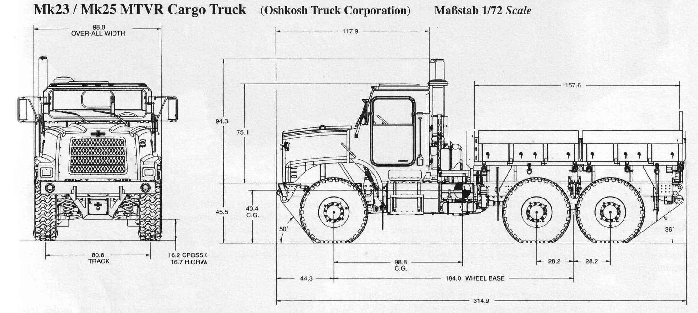
If you study the steering arms on the #3 and #4 axles in the Oshkosh/Pierce drawing you may notice that they are of different lengths. The rear most axle's steering arms are longer. This allows the rear most axle to turn to a greater degree (angle) than the #3 axle.
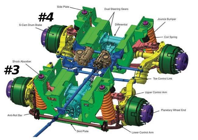
I suspect both the axle #3 steering arms and the pitman arms attached to the steering gearboxes are a shorter length as well.
I must admit I tip my hat to the designers. I MAY perhaps know how something like this might work theoretically but how the folks at Oshkosh worked out all the engineering math to make this all function in reality is WAY beyond me!
Kudos to those folks!
165thspc
#521
Joined: April 13, 2011
KitMaker: 9,465 posts
Armorama: 8,695 posts
Posted: Sunday, November 13, 2016 - 12:48 AM UTC
Most all this stuff is just my conjecture based on the research I have found so far. Please feel free to shoot holes in my theories if you think I have something wrong.
To me it is way more important for the model to be right than it is for me to be right!
To me it is way more important for the model to be right than it is for me to be right!
Thirian24
Joined: September 30, 2015
KitMaker: 2,493 posts
Armorama: 2,344 posts
Posted: Sunday, November 13, 2016 - 01:42 AM UTC
I really respect the level of research you put into your builds.
165thspc
#521
Joined: April 13, 2011
KitMaker: 9,465 posts
Armorama: 8,695 posts
Posted: Sunday, November 13, 2016 - 01:51 AM UTC
Pierce Fire Equipment "Rear Steer" video demos:
https://www.youtube.com/watch?v=UkyjDwOA6Cw
https://www.youtube.com/watch?v=1VSVnuXCeYc
https://www.youtube.com/watch?v=UkyjDwOA6Cw
https://www.youtube.com/watch?v=1VSVnuXCeYc
165thspc
#521
Joined: April 13, 2011
KitMaker: 9,465 posts
Armorama: 8,695 posts
Posted: Sunday, November 13, 2016 - 02:53 AM UTC
Dustin - Thanks! I do try in the research dept.
__________________________________________________________________________________________
As to the steering gear this is what I am now thinking:
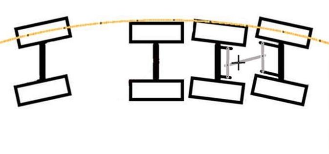
At the center of the black cross is where I think the steering gearbox or boxes would be located.
__________________________________________________________________________________________
As to the steering gear this is what I am now thinking:

At the center of the black cross is where I think the steering gearbox or boxes would be located.
165thspc
#521
Joined: April 13, 2011
KitMaker: 9,465 posts
Armorama: 8,695 posts
Posted: Sunday, November 13, 2016 - 06:08 AM UTC
This is more of my photoshop work and NOT actual construction but I think I'm getting close to cutting actual plastic.
I added the fourth axle of course, then added a frame extension right behind the cab. (The two white tick marks below the frame show the length of this extension.) Finally, I shortened the length of the tail frame just behind the last axle.
I added the fourth axle of course, then added a frame extension right behind the cab. (The two white tick marks below the frame show the length of this extension.) Finally, I shortened the length of the tail frame just behind the last axle.

165thspc
#521
Joined: April 13, 2011
KitMaker: 9,465 posts
Armorama: 8,695 posts
Posted: Sunday, November 13, 2016 - 06:36 AM UTC
Would anyone happen to have basic dimensions on the 16.5 ton LHS?
__________________________________________________________________________________________________
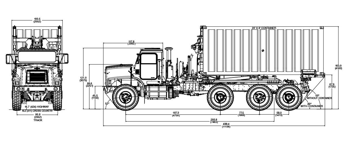
At Gino's recommendation I scaled out the entire vehicle based on the container being 20' long.
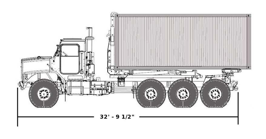
CORRECTION: I finally found the overall length posted in an OSHKOSH publication. Their published figure is 33 feet, 6 inches measured to the rear end of the "tilt-load" equipment!
For the time being I am not going to rely on this overall vehicle length measurement being exactly correct. I don't completely trust it just yet! I want to find the same data printed somewhere else before I trust my attempts to scale this drawing.
__________________________________________________________________________________________________
At Gino's recommendation I scaled out the entire vehicle based on the container being 20' long.

CORRECTION: I finally found the overall length posted in an OSHKOSH publication. Their published figure is 33 feet, 6 inches measured to the rear end of the "tilt-load" equipment!
For the time being I am not going to rely on this overall vehicle length measurement being exactly correct. I don't completely trust it just yet! I want to find the same data printed somewhere else before I trust my attempts to scale this drawing.
165thspc
#521
Joined: April 13, 2011
KitMaker: 9,465 posts
Armorama: 8,695 posts
Posted: Sunday, November 13, 2016 - 09:38 PM UTC
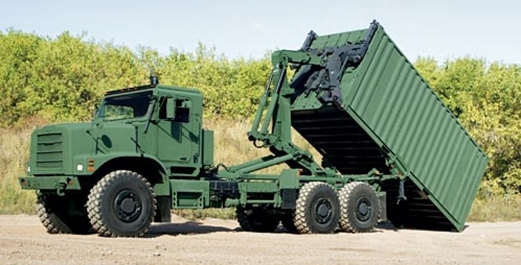
Just an F.Y.I. - this vehicle also comes in a 9 ton three axle LHS version. In this photo it looks like the #2 axle possibly uses torsion bar suspension???

M4A1Sherman
Joined: May 02, 2013
KitMaker: 4,403 posts
Armorama: 4,078 posts
Posted: Sunday, November 13, 2016 - 10:43 PM UTC
Quoted Text
This is more of my photoshop work and NOT actual construction but I think I'm getting close to cutting actual plastic.
I added the fourth axle of course, then added a frame extension right behind the cab. (The two white tick marks below the frame show the length of this extension.) Finally, I shortened the length of the tail frame just behind the last axle.
YESSS!!!

More Mike Koenig-type WONDERFULNESS!!!

HeavyArty

Joined: May 16, 2002
KitMaker: 17,694 posts
Armorama: 13,742 posts
Posted: Sunday, November 13, 2016 - 10:58 PM UTC
Quoted Text
Would anyone happen to have basic dimensions on the 16.5 ton LHS?
No measurements, but by scaling this up to 1/35, you should be able to work them out pretty easily, esp. knowing that the container is 20' long.
You should also be able to extrapolate the numbers by comparing it to this one too.
I also found this. It looks like it has a different wheel spacing and something else between the cab and load though.
165thspc
#521
Joined: April 13, 2011
KitMaker: 9,465 posts
Armorama: 8,695 posts
Posted: Sunday, November 13, 2016 - 11:31 PM UTC
Well you are right Gino, having a 20' container in the drawing SHOULD make it fairly easy to scale up! Sometimes I can be rather stupid, woods for the trees and all that!
Do not know what that bottom drawing might be, an early design prototype perhaps or a product for the European market???
Do not know what that bottom drawing might be, an early design prototype perhaps or a product for the European market???
HeavyArty
Joined: May 16, 2002
KitMaker: 17,694 posts
Armorama: 13,742 posts
Posted: Sunday, November 13, 2016 - 11:44 PM UTC
Quoted Text
Do not know what that bottom drawing might be, an early design prototype perhaps???
No clue. It came off a French site, so I couldn't understand what it was saying.

Frenchy

Joined: December 02, 2002
KitMaker: 12,719 posts
Armorama: 12,507 posts
Posted: Monday, November 14, 2016 - 12:20 AM UTC
Here's a larger version of the side view in Gino's post :
http://www.maquetland.com/v2/images_articles/33333.JPG
The French website is the one where I've found the pics I sent to you yesterday Mike
H.P.
http://www.maquetland.com/v2/images_articles/33333.JPG
The French website is the one where I've found the pics I sent to you yesterday Mike
H.P.
Frenchy
Joined: December 02, 2002
KitMaker: 12,719 posts
Armorama: 12,507 posts
Posted: Monday, November 14, 2016 - 02:42 AM UTC
Mike
I've just realized that the Eurosatory pics I've sent you show the longer variant seen in these drawings :
http://www.maquetland.com/v2/images_articles/33333.JPG
so they may be not as useful as I thought they could be...
H.P.
I've just realized that the Eurosatory pics I've sent you show the longer variant seen in these drawings :
http://www.maquetland.com/v2/images_articles/33333.JPG
so they may be not as useful as I thought they could be...
H.P.
165thspc
#521
Joined: April 13, 2011
KitMaker: 9,465 posts
Armorama: 8,695 posts
Posted: Monday, November 14, 2016 - 06:21 AM UTC
Thanks Frenchy - I am still managing to get info out of them that can work for my truck.
HeavyArty
Joined: May 16, 2002
KitMaker: 17,694 posts
Armorama: 13,742 posts
Posted: Monday, November 14, 2016 - 06:28 AM UTC
Quoted Text
Do not know what that bottom drawing might be, an early design prototype perhaps???
Quoted Text
I've just realized that the Eurosatory pics I've sent you show the longer variant...
Maybe it is a version they are offering to the European market. Still not sure what is between the cab and lift mechanism though.
Larger pic.
165thspc
#521
Joined: April 13, 2011
KitMaker: 9,465 posts
Armorama: 8,695 posts
Posted: Monday, November 14, 2016 - 08:02 AM UTC
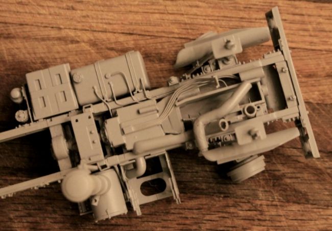
Took a tip from Gino (just one?) and added the intake and exhaust pipes under the hood. Then took it one better to add some piping and electric lines under the cab.

165thspc
#521
Joined: April 13, 2011
KitMaker: 9,465 posts
Armorama: 8,695 posts
Posted: Monday, November 14, 2016 - 08:05 AM UTC
 |

WEB HOSTING BY


Copyright ©2021 Armorama and Kitmaker Network, a subsidiary of Silver Star Enterprises
All Rights Reserved. Please read our Conditions of Use and Privacy Policy.
All Rights Reserved. Please read our Conditions of Use and Privacy Policy.