Quoted Text
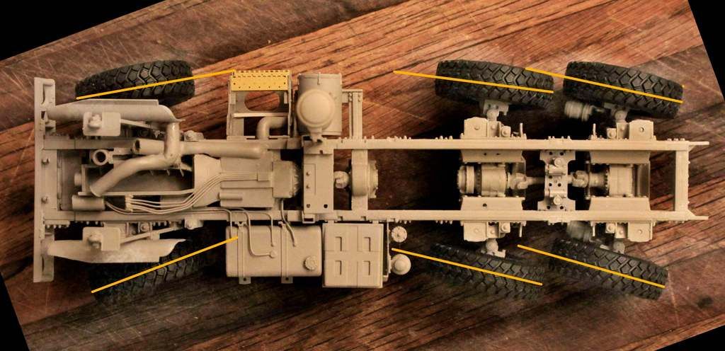
Dennis is it possible that you are looking at the rear axles as having what you would consider an excessive amount of toe-in?
I believe that in rear wheel steering the "toe value" is roughly a reverse mirror image compared to that of the front steering axle. The rear steering axles toe-in should be looked at, and measured, as though the vehicle were rolling in reverse.
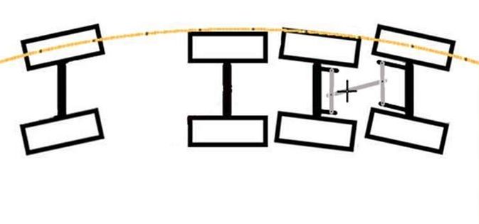
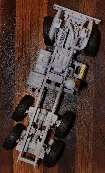
I know my wheel steering angles are not EXACTLY right but I think they are in the ball park, however I realize I could be totally wrong.
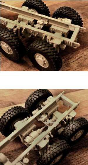
As to the wheel camber, I let the structure of the model itself dictate what camber that it would, which I admit is very little. However the double A-arms of the Oshkosh suspension are of equal length and it appears the design itself does not allow for much in the way of camber in the steering geometry. If I am correct in this camber question I do not know. Also what this may imply for this particular vehicle design I again, do not know.
Hi, Mike, and Everyone else!

OK, let me try a different tack, here. Whether it's the Front Wheels/Tires or the Rear set, the same rules of Caster, Camber, Toe-In, and Toe-Out On Turns still apply:
Camber: Looking "Head-On" from the Front, (standing at the Front of the vehicle, and looking at the Nose) AND the Rear, (standing at the Rear of the vehicle, and looking at the Rear End), the Wheels/Tires should be splayed OUTWARDS, i.e, Right and Left, at the TOPS of the Wheels/Tires- This shouldn't be exaggerated by any means, but this characteristic should be, at the very least, noticeable if one looks closely.
What I do to present Camber, is that I like to GENTLY apply slow, steady pressure downwards to the Axle Spindles, altering the Axles to point slightly down, when viewed from "head-on", or from the rear. Too much pressure will break the Axle Spindles, so a light hand is essential in doing this. For "newbies", I suggest practicing on pieces of sprue before attempting this technique.
Toe-In: If the Wheels/Tires are modeled as traveling "straight-ahead"- Looking from Above and/or Below the vehicle, ALL Wheel/Tire assemblies, regardless of their positions on the Chassis, i.e, Front, Middle or Rear, should show a VERY slight Toe-In, or what I sometimes call "pigeon-toed-ness".

On real vehicles, this is essential in order to prevent the Wheels/Tires from splaying Outwards at the Front when the vehicle is traveling Forwards. This outward splaying becomes progressively worse as road speeds are increased. We travel forwards probably 99% of the time, rather than backwards as a general rule. As I mentioned in my previous post, this is to prevent the splaying of the Wheels/Tires. This splaying in turn, will cause the the vehicle to wander VERY excessively, and cause excessive Tire & Tie Rod End Wear, because the Right and Left Wheels/Tires want to travel in opposite directions as you're driving forwards. Tires and Tie Rod Ends are expensive, plus constantly having to fight your steering directions and maintaining a straight line down the road can be pretty darned frustrating into the bargain...

The Upper and Lower "A" Arms don't necessarily need to be of equal lengths; the designs of the "A" Arms vary between vehicle manufacturers- The adjustments for Camber are made at either the Top "A" Arm, or at the Bottom "A" Arm, most commonly in the Upper and/or Lower Ball Joints, depending on the design that any particular manufacturer chooses to use in their products. The actual Length of the Upper and Lower "A" Arms have NOTHING to do with ANY Wheel Alignment adjustments.
I'm SURE that you understand the Toe-Out On Turns, judging from your latest line-drawing in your last post.
Now, on plastic models with "pose-able" steering, the model manufacturers all too often leave you with way too much "slop" in the Steering assemblies' parts, just to facilitate ease of "posing" your Wheels/Tires in any direction you happen to choose. This "slop" will COMPLETELY throw the model's "Wheel Alignment" out of kilter. The WEIGHT of the model will determine how much the Wheels/Tires will splay OUTWARDS AT THEIR BOTTOMS, rather than at the TOP, when the model is placed on a flat and level surface. The model's "Wheel Alignment" will thus be rendered as COMPLETELY INCORRECT, presenting a decidedly "KNOCK-KNEED" appearance when viewed from virtually ANY angle. The ONLY way that proper Wheel Alignment really works on wheeled vehicle models, is to CEMENT the parts of your whole steering assembly in place, once you've decided on which direction you want to pose your Wheels/Tires. IMO, if you leave all the "slop" in your Wheels/Tires and their respective Steering Mechanisms, you're gonna wind up with a model that has cock-eyed looking Wheels...
Call me obsessive, but over 25 years of experience in the Automotive and Heavy Machinery businesses have made me a STICKLER for accuracy. Once AGAIN, let me STRESS that I AM NOT CRITICIZING your work, merely making SUGGESTIONS...

BTW, speaking to the modellers who "cross-cultures", these basic Wheel Alignment tenets also apply to scale Aircraft Landing Gear Wheels and Tires, EXCEPT for Toe-Out On Turns. Aircraft are steered without any automotive-style steering mechanisms-
Aircraft steer by several different methods, i.e, with "Tail-Draggers", (Aircraft with tail Wheels, as opposed to Aircraft with Nose Wheels), by the Pilot(s) applying brake pressure at the tops of either the Right or Left Rudder Pedals where the Brake Actuating Mechanisms are located, OR by unlocking the Tail Wheel, AND using the Rudder Pedals, applying Brake Pressure at the same time. Interestingly, this method of steering is kind of similar to steering tracked vehicles, along with Steering Levers which activate the Steering Clutches, which are located internally, outboard of the Transmission...
In the predominating cases of Aircraft with Nose Wheels, the Pilot(s) will use the Control Wheel (as with wheeled ground vehicles), along with Brake Pressure, applied by using the tops of the Rudder Pedals.
Slight Camber and Toe-In are DEFINITELY required on Aircraft, what with their high Take-off & Landing speeds, and their much heavier weights notwithstanding...



_files/otu18.jpg)


