

1⁄35Sdkfz 251/17 Ausf C
7
Comments
Detailing the Interior
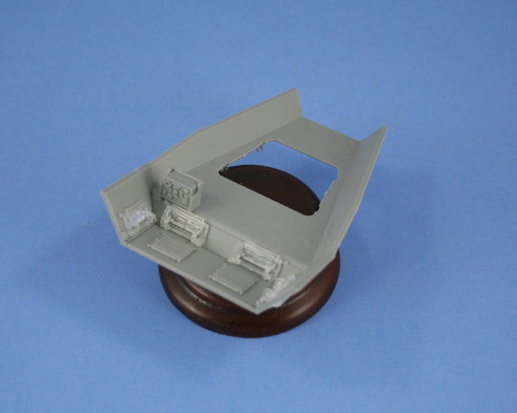
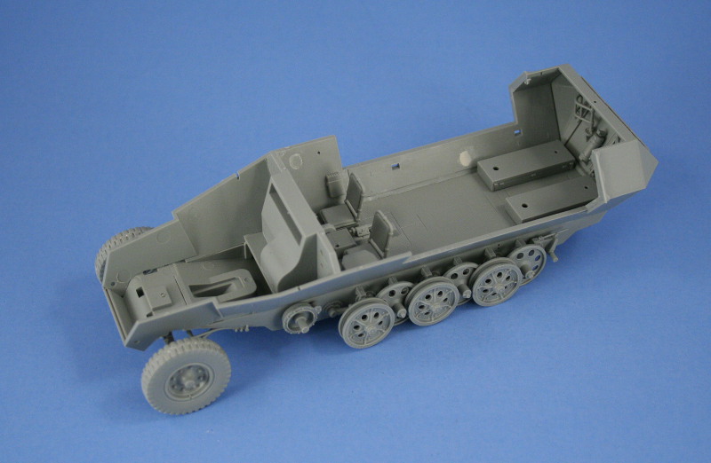
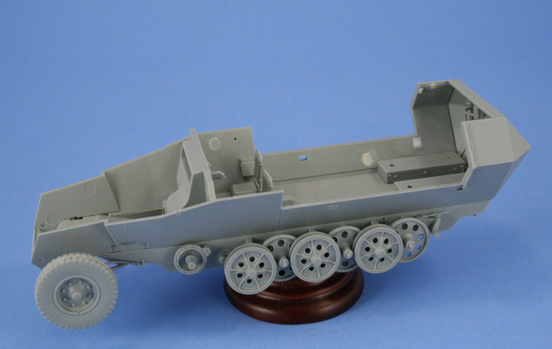
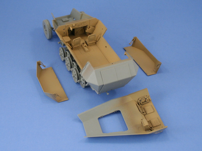
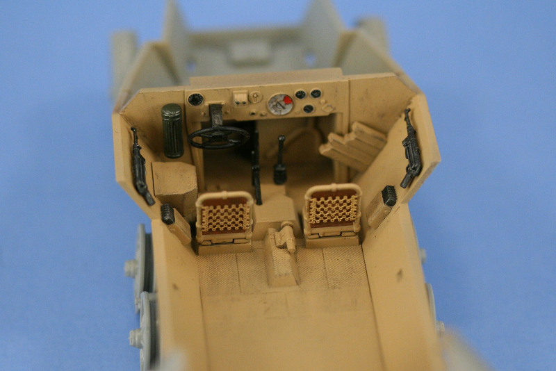
The kit provides the standard interior details for the drivers area from previous Ausf C kits, including the instrument panel with raised details for the gauges. In order to facilitate easier detailing, only the large parts were installed at first and the seats were secured with blue tack to allow them to match the rest of the interior when painted before the seat cushions and PE spring backs were detailed or added. The kit instructions indicate that decals are available for the faces of the instrument gauges but these are not included in this kit since the decal sheet they normally are on was replaced with a new sheet specific for this variant, leaving hand-painting them as the only option to add their details. Since the design of the 251-17 results in so much of the interior being exposed, I elected to hold off installing the floor and drivers area until I had the hull sides and rear hull areas completed and could insure an even fit with the floor and side hull panels. The side panels had several large sink marks that needed to be dealt with at the front and rear which ordinarily would be hidden by the standard seats and bins but on this version they are visible, so some putty and sanding attention was required. At the rear of the compartment an option is provided to install the standard bench-type seats or single post support seats on either side. The floor has mount holes designed for the bench-type already opened which would have to be filled if using the post support seats. I decided to go with the bench-type design to avoid this after checking the one photo showing the rear interior available in Squadron's [i]251 In Action[/i] seemed to indicate the bench style was the type used. I also constructed the rear hull section, including the top, off the vehicle in order to get a solid fit on both areas prior to installation. The rear crew doors have a complicated hinge construction and installation that can be assembled to have the doors remain workable if careful but I opted for the permanently closed position for convenience and added support for the doors. Care was needed on the Step 9 instruction diagrams as the posts are designed to be trapped between hinge points on both the doors and the sides and hull tops, however the instructions dont call for that to happen until Step 10, making the assembly tricky if followed to the letter. The front hull and cab roof were also assembled at this time, with the drivers front and side visors a combination of grey and clear styrene parts. All of the visors were installed in the closed position with the armored glass portions masked off with blue tack to protect them during painting. I also installed the two head-bump pads on the underside of the cab roof for both the driver and radio-operator seats, although this is strangely neglected in the instructions. The parts, B32 and B33, are present on the sprues but marked as not for use but once located they were installed in their proper places. The final detail for the interior before painting involved the hull drop-down sides. These are provided as excellent one-piece parts requiring the construction of their hinge arms and locking plates for attachment to the front and rear hull sides. The instructions have the hinge arms parts numbers reversed, just one of many pitfalls encountered in the instructions for this kit to watch out for. The hull sides were then installed along with the floor and another issue appeared. The hull side panels have square cut-outs designed to take the mount tabs for the fenders and the rear-most cut-outs would be visible if left unattended. I elected to use some sheet styrene, cut to 3mm x 3mm squares and glued directly to the hull with liquid glue, then sanded flush, to address the problem instead of installing the fenders and using putty to fill the holes. Once that was accomplished, the interior was primed with Testors enamel Italian Dark Brown and then given a base coat of RAL 8020 Afrika Braun. The interior details left off previously for the drivers area were painted and installed along with the rear seats. Once satisfied, the upper hull and roof were joined to the lower hull along with the armored nose plate, requiring only some light finger pressure in various spots to get a solid join and keep everything aligned.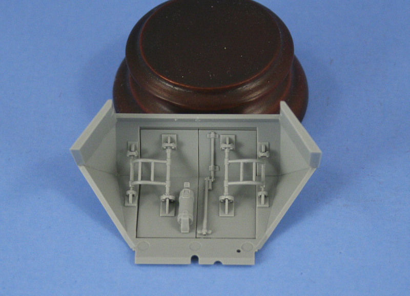
About the Author


FROM: TEXAS, UNITED STATES
Like many, I started out in the hobby as a kid building airplanes to hang from my bedroom cieling. I took a long break from the hobby, returning in 2001 with an interest in armor inspired mostly by online gaming. WW2 armor, 1/35 scale, is my preferred genre with a special taste for the stranger vehi...
Comments


Bill, as always a nice feature from you. Good build (love the camo) and good concrete article.
Thanks for your time and effort
JUN 18, 2007 - 09:55 PM


Great build article Bill and one i will definatly be refering to when i get around to building my halftracks, the painting and weathering turned out great also.
Ron.
JUN 19, 2007 - 03:30 AM
Copyright ©2021 by Bill Plunk. Images and/or videos also by copyright holder unless otherwise noted. The views and opinions expressed herein are solely the views and opinions of the authors and/or contributors to this Web site and do not necessarily represent the views and/or opinions of Armorama, KitMaker Network, or Silver Star Enterrpises. All rights reserved. Originally published on: 2007-06-17 00:00:00. Unique Reads: 35728

WEB HOSTING BY


Copyright ©2021 Armorama and Kitmaker Network, a subsidiary of Silver Star Enterprises
All Rights Reserved. Please read our Conditions of Use and Privacy Policy.
All Rights Reserved. Please read our Conditions of Use and Privacy Policy.