

1⁄35Sdkfz 251/17 Ausf C
7
Comments
Exterior hull and fenders
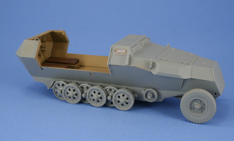
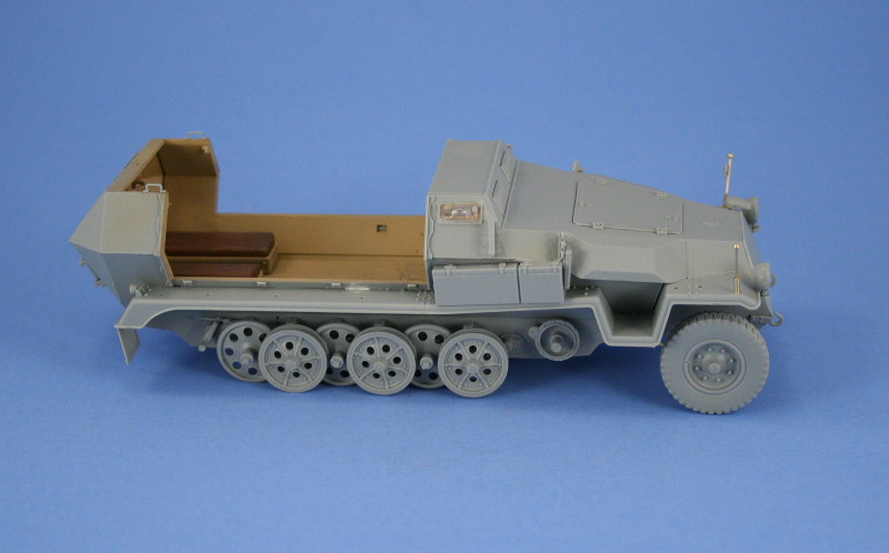
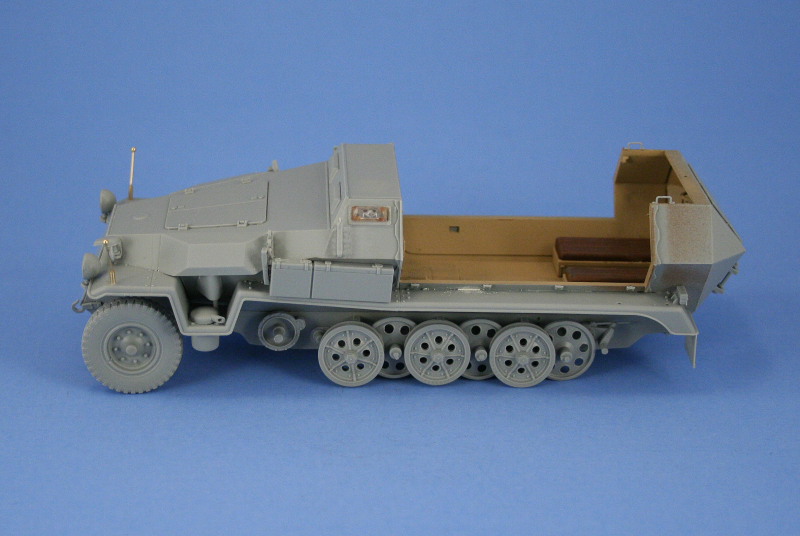
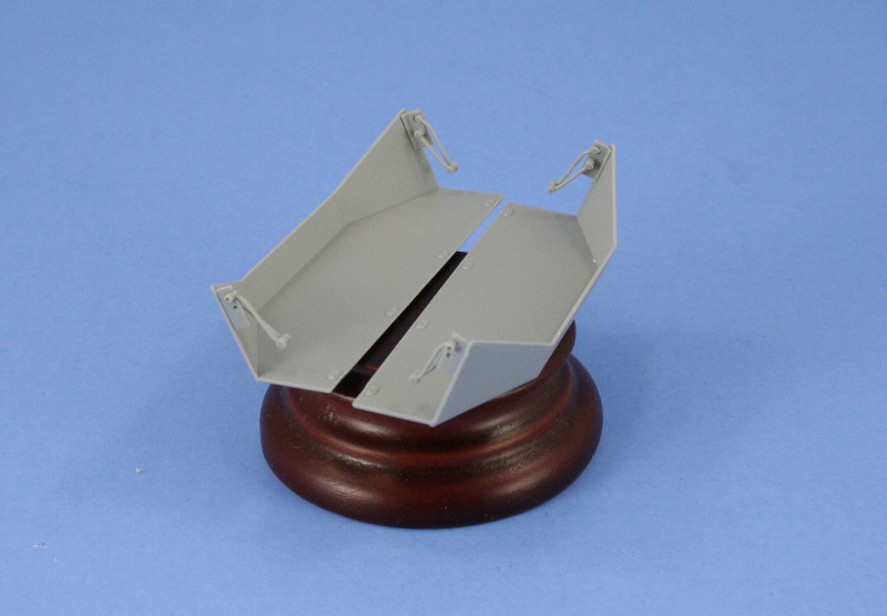
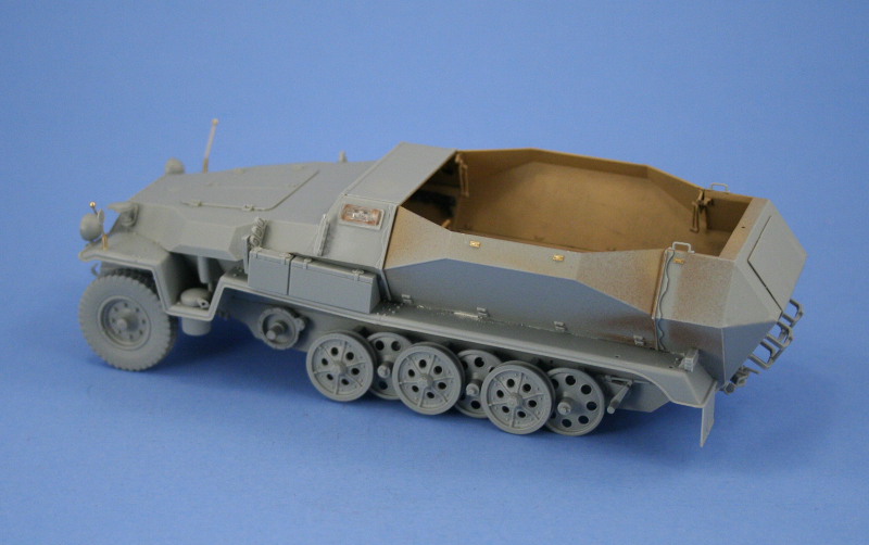
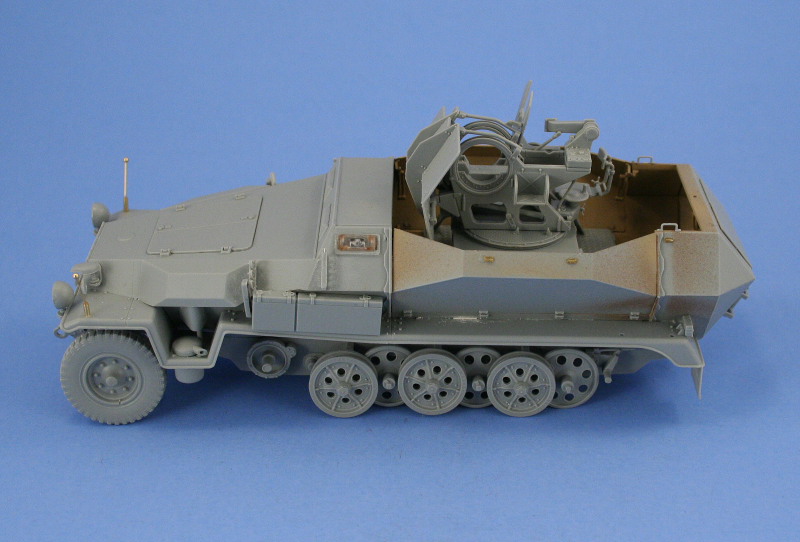
With the interior squared away, my attention turned to the exterior details and items that had been bypassed in the preceeding steps. The engine hatches and armored vent covers were installed on the front hull along with the crew rifle racks. The kit includes 6 Mauser rifles to mount in these but all the reference photos available to me showed them empty, so I opted to leave the rifles off and destined for the spares bin. I also elected to install on the rear crew doors a pair of jerry can racks to add some additional variation suitable for a N. Africa vehicle as a personal choice. I was unable to find any reference photos of Tunisia 251/17s, so it's pure speculation on my part that they would be fitted, but I felt they added a little detail touch especially since the included cans have nice details themselves as well. Next up were the fenders and I discovered that Step 11 in the instructions contains numerous errors ranging from parts mislabeling to incorrect parts assembly, so a lot of caution and checking was necessary to get through this phase of the build. The largest error came in the form of the unique side storage bins which are supposed to be installed with the smaller box at the front on both sides and the instructions gets this wrong. The boxes are also supposed to install directly to the hull, not to the fenders, since the boxes overhang the fenders and need to sit flush against the hull. This step also ignores the installation of the blackout convoy light on the left side and the rear brake light for the right although both are provided on the sprues as parts B9 and B13 and marked as not for use. I ignored this and installed them in their respective locations. The remaining details for the front fenders in the form of the front blackout lights, brass width indicator poles bent to shape using the jig on the back of Sprue C, turn indicators, Notek light, and pot exhaust/muffler were also installed. The pioneer tools were left off to allow for separate painting and detailing before being installed later on. The final little touches involved the still visible gaps for the slot tabs on the exterior. These were filled with putty and sanded down. The lower hinges for the drop down sides were also installed and the drop sides fitted into place. These are a tight fit, requiring careful adjustment to get them to sit straight on both sides and just a little bit of liquid glue to secure in place. I opted to fix these in the closed position as the hinge arms arent workable and I didnt have any diorama plans for the finished build. The kit-included PE foliage loop brackets were installed as well to finalize this area, these are very small and very fragile, and even with the greatest of care throughout the paint and finish stages, not all of them made it to the finish line unfortunately.Flak 38 Assembly
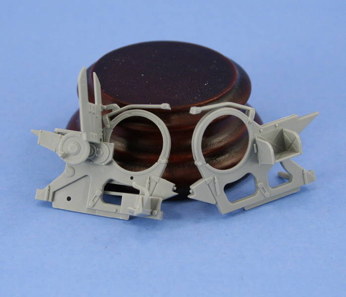
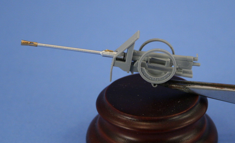
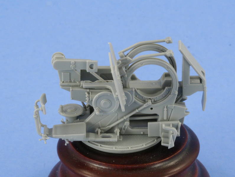
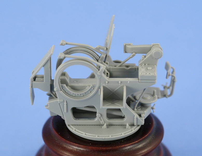
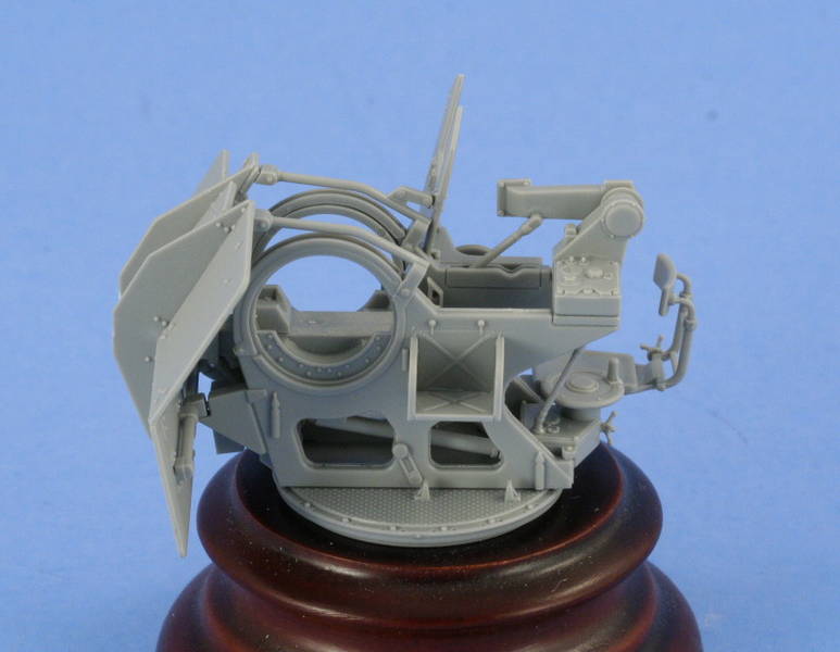
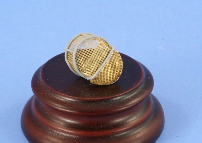
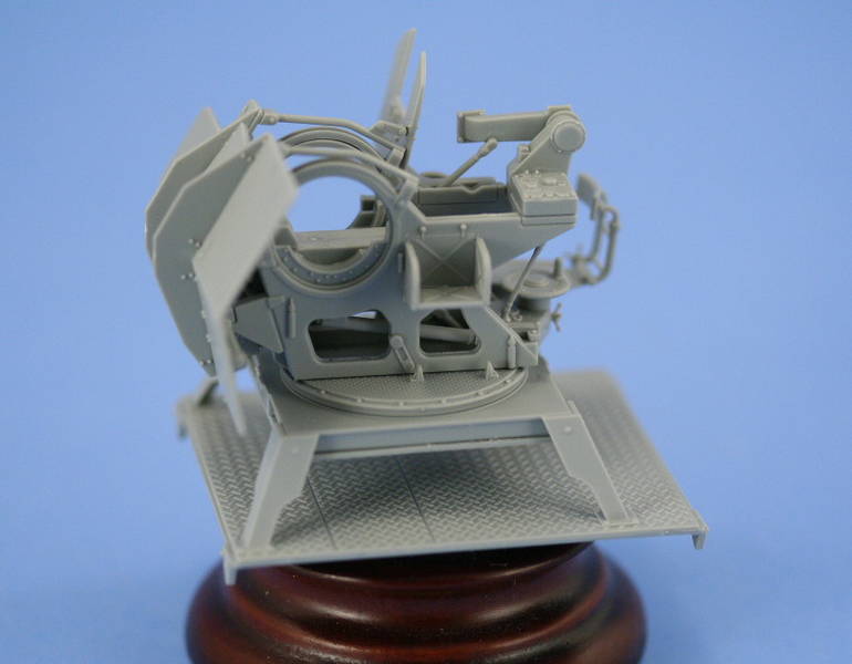
Construction of the Flak 38 proceeded smoothly. The kit parts are all from the previous kit release including the trailer and other details, although most of those arent used for this vehicle. The left and right sides of the gun mount assembled without issue and while the kit includes PE parts for the gunners sight splinter shield, I opted to stay with the styrene one-piece to stay consistent with the rest of the splinter shield parts for the gun itself. The barrel replacement surgery to accommodate the Armorscale barrel was very straightforward, requiring the removal of the matching portion on the kit supplied one-piece styrene barrel with sprue cutters, drilling a hole in the remaining styrene base to accept the barrel, then gluing with CA gel to mate the two up. I left the barrel removable from the cradle to allow it be detailed and painted separately before final installation. Assembly of the mounts and attachment to the base plate proceeded with appropriate parts chosen to construct the gun at 0 degrees elevation. The kit provides the options for 0, 20, 40, or 60 degrees but the choice must be made between one of the 4 during assembly to get the proper elevation match between the gun and the gunners sight. I also assembled the kit supplied PE and styrene parts for the spent-shell basket. The PE parts are a combination of delicate fine mesh for the interior portions and pre-formed brass halves for the bottom basket. The mesh was carefully installed and tacked in place with CA gel, taking care to form the pieces to the frame supports with the end of a paint brush handle and avoid tearing the mesh in the process. The pre-formed halves were soldered together and then glued with CA gel to the base of the basket frame to complete the assembly. I assembled the gun-sight and drilled out the eye-piece on the direct-fire scope with a pin vise, leaving it off for now to allow for later detail painting. In later steps, the sight would be painted with Aircraft Interior Black with the main sight glass simulated with Silver over painted with Tamiya Clear Green and then installed. The main splinter shields were assembled and dry-fit to insure they mated up properly with the gun mount top and bottom points. The shields were left removable to facilitate painting of the mount and also to prevent overspray when the camo pattern would be applied. The pedestal mount and base plate for the interior were assembled and test-fit to insure the gun would sit properly inside the hull and everything was ready for painting.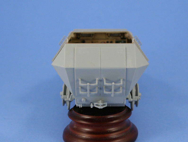
About the Author


FROM: TEXAS, UNITED STATES
Like many, I started out in the hobby as a kid building airplanes to hang from my bedroom cieling. I took a long break from the hobby, returning in 2001 with an interest in armor inspired mostly by online gaming. WW2 armor, 1/35 scale, is my preferred genre with a special taste for the stranger vehi...
Comments


Bill, as always a nice feature from you. Good build (love the camo) and good concrete article.
Thanks for your time and effort
JUN 18, 2007 - 09:55 PM


Great build article Bill and one i will definatly be refering to when i get around to building my halftracks, the painting and weathering turned out great also.
Ron.
JUN 19, 2007 - 03:30 AM
Copyright ©2021 by Bill Plunk. Images and/or videos also by copyright holder unless otherwise noted. The views and opinions expressed herein are solely the views and opinions of the authors and/or contributors to this Web site and do not necessarily represent the views and/or opinions of Armorama, KitMaker Network, or Silver Star Enterrpises. All rights reserved. Originally published on: 2007-06-17 00:00:00. Unique Reads: 35728

WEB HOSTING BY


Copyright ©2021 Armorama and Kitmaker Network, a subsidiary of Silver Star Enterprises
All Rights Reserved. Please read our Conditions of Use and Privacy Policy.
All Rights Reserved. Please read our Conditions of Use and Privacy Policy.