Hi Everyone,
Been a little while since the last update, but that's due to having to actually BUILD before I can post!

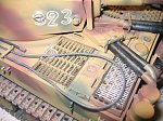
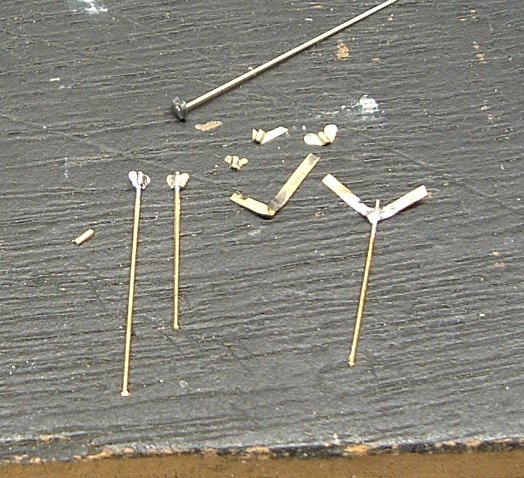
After the supporting flanges were in place on the sponson, I had to make some bolt heads for the top chord. They were made easily enough out of little stubs of stretched sprue glued, then cut and sanded to height.
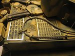
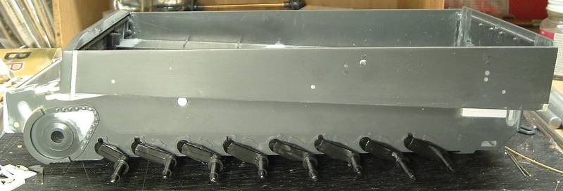
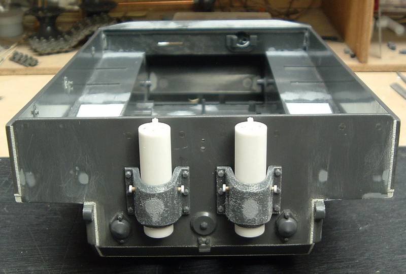
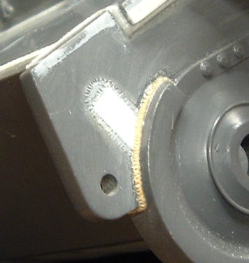
An overview of the finished flange in place:
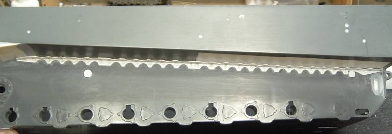
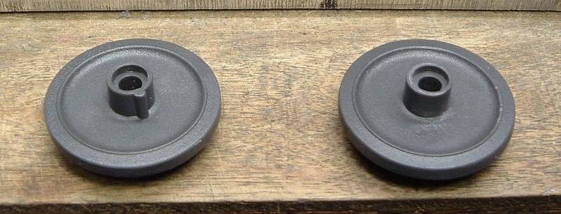
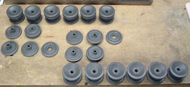
Also note in the overview, I cut some disks from Evergreen to simulate the shock absorber mounting points. Anyone know if these were thicker than I've depicted?
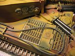
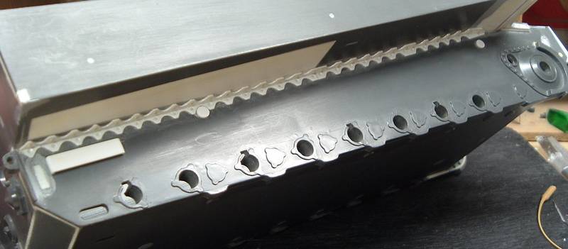
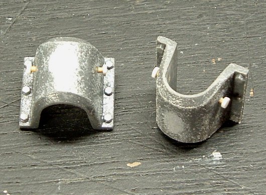
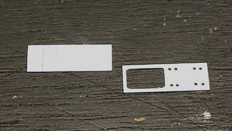
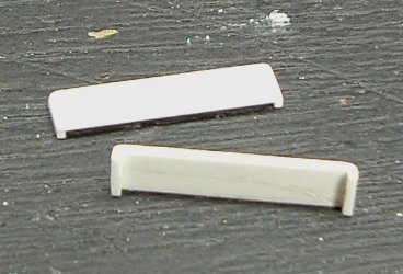
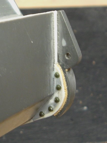
The lower hull detail is almost done at this point with the exception of the track pin plate. It's made up of some Evergreen stock cut to size, short legs glued on the ends, then rounded the corners over.
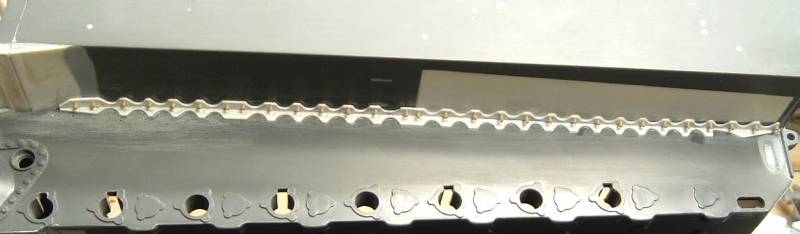
Here it is in place with the (groan) weld beads.
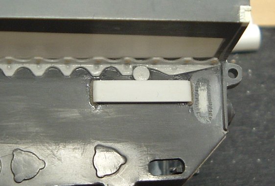
Now I just have to finish up the other side ...
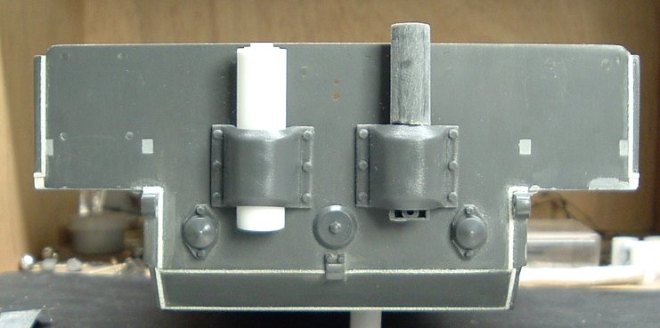
Jumping around a bit, there was some work to be done to the front end before I could move to the hull rear.
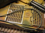
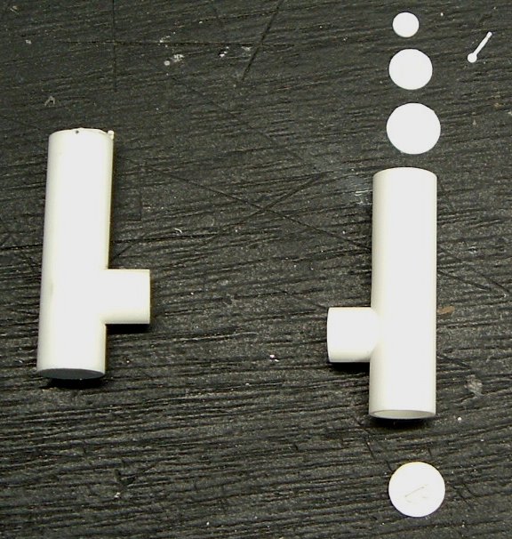
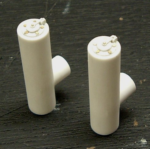
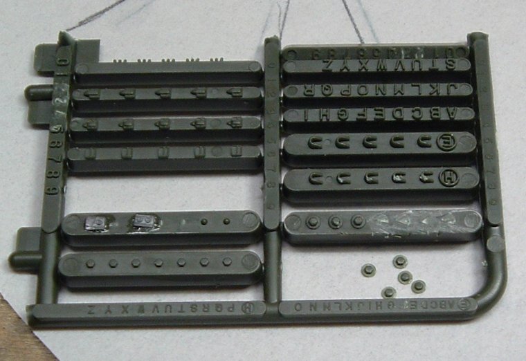
The insides of the final drives needed some bolt heads and weld beads. I used the bolts from an Academy sprue someone sent me. Think it's from a US M-10 or something like that???
And glued into position with the accompanying weld beads.
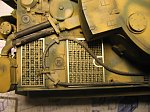
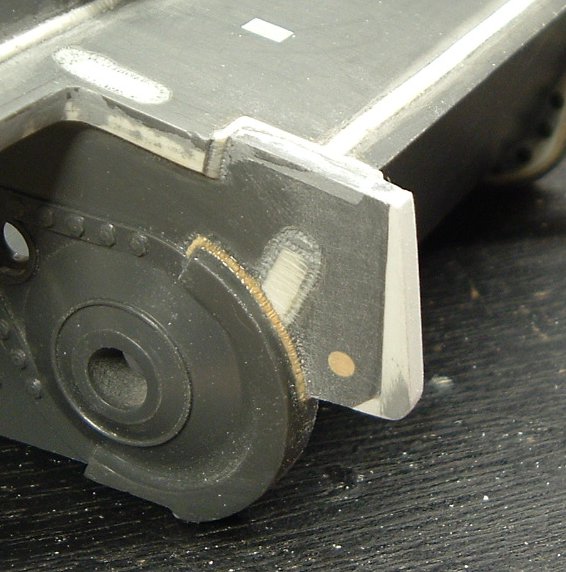
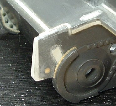
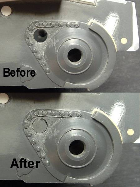
Looking at the model with a pair of somewhat fresh eyes, I saw a MAJOR weld bead missing between the bow armored plate and the hull sides. Here is a little SBS on how I added them.
Disclaimer: this is NOT my technique, but something that I've seen, and works for me. Tony Greenland's? Pat Stansell's? I forget, but definitely can't claim any credit on my part lol
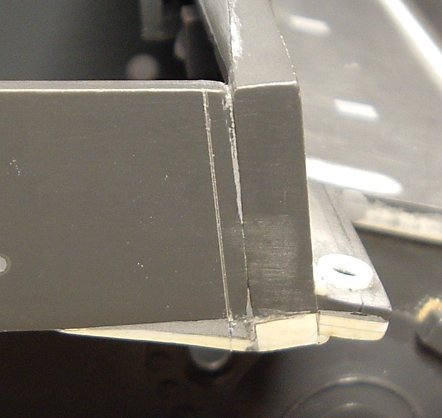
1. Measure weld bead width.
2. Cut a V shaped notch into the plastic.
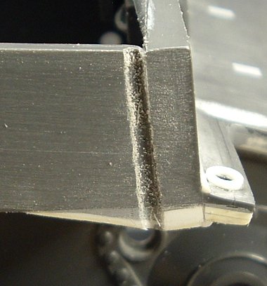
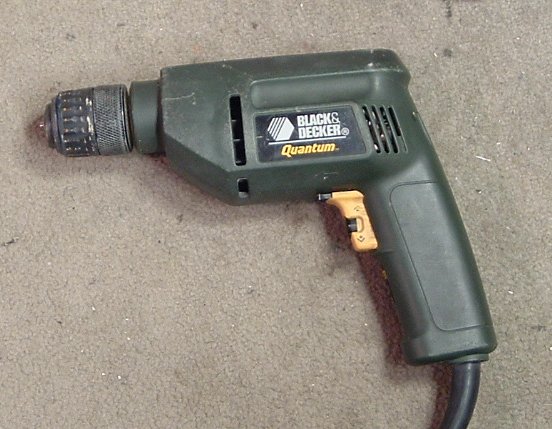
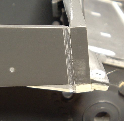
3. Clean out notch with motor tool.
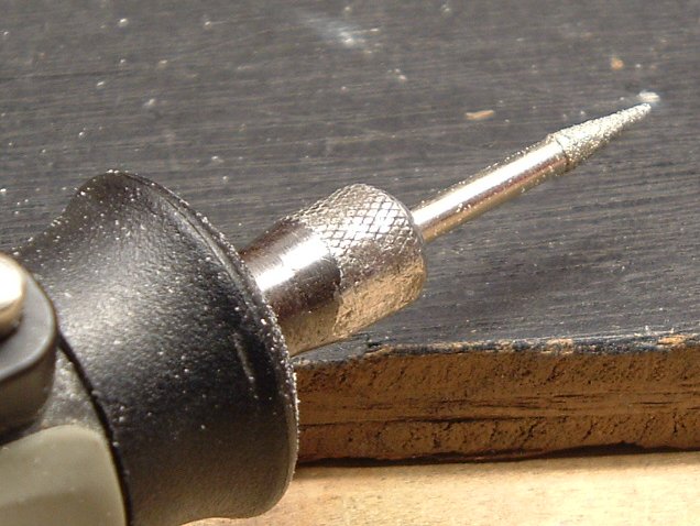
(Said motor tool and bit)
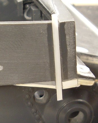
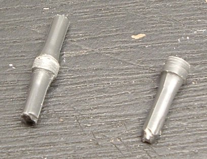
4. Glue in half round Evergreen stock.
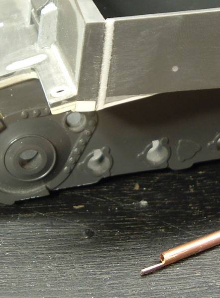
5. Finished textured weld bead from the other side.
That's about it for now, currently working on the driver's visor and MG mount. Questions, comments, corrections welcomed as always!
Matt