_GOTOBOTTOM
Armor/AFV: Allied - WWII
Armor and ground forces of the Allied forces during World War II.
Hosted by Darren Baker
IBG Marmon-Herrington Mk II Middle East Type
Thudius
Visit this Community
Uusimaa, Finland
Joined: October 22, 2012
KitMaker: 1,194 posts
Armorama: 1,077 posts
Posted: Sunday, May 11, 2014 - 10:47 PM UTC


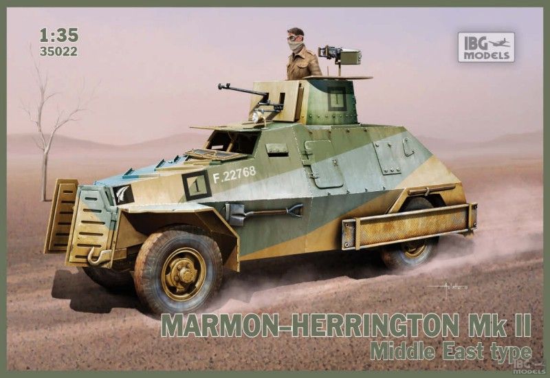
The fine folks here at Armorama have seen fit to let me do another build review, this time around it's the lovely little Marmon-Herrington Mk II Middle East type (kit 35022) from IBG in 1/35th scale. I've typically done straight out of the box builds previously so that the reader could see what they get in the box rather than what you could get when you start to add missing details. This will be mostly OOB, there are a few, let's call them oversights, that mean a strict OOB didn't make sense to me. More on these oversights as we get along.


First off, to see what you get in the box, I refer you to Russ Ammot's look at IBG's Panzerspahwagen Marmon-Herrington (e) https://armorama.kitmaker.net/review/9724

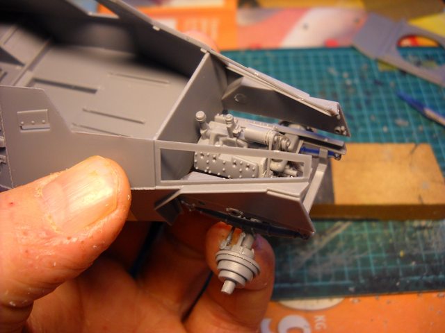
A quick comparison of sprues shows that the only differences with these two kits are the hull sides and front fenders, a turret (different from the Mk I), markings and the inclusion of a weapons sprue. Only a few parts are marked as not used, so not much left over for the spares bin.

I'll be using whatever references I could source from the internet, sadly there isn't much. There is a book available that by all accounts is quite good and useful https://armorama.kitmaker.net/news/13846

A big shout out and thanks to Stephen Tegner for making the following photos of a Mk I, Mk III and No 19 radio set available:

http://s554.photobucket.com/user/Tegner/library/Marmon%20Herrington%20Mk1?sort=3&page=1

https://plus.google.com/photos/+StephenTegner/albums/5872261696003956033?banner=pwa

https://plus.google.com/photos/+StephenTegner/albums/5871659203693131793

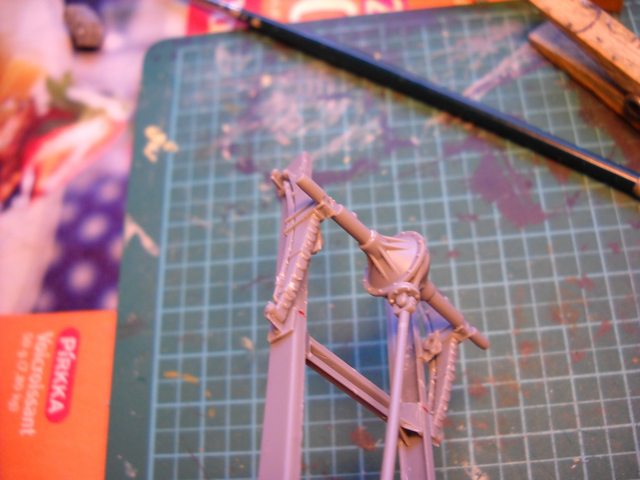
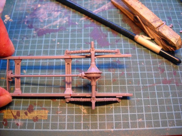
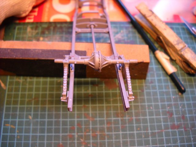
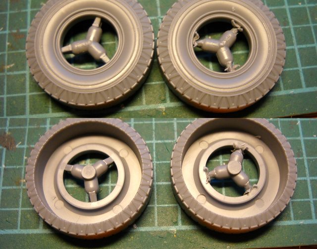
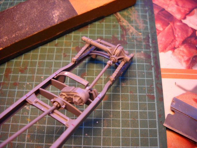
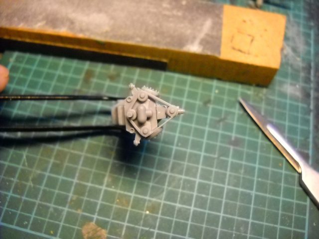
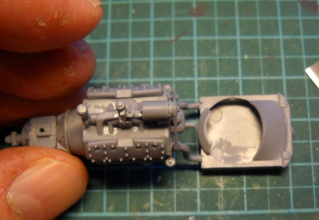
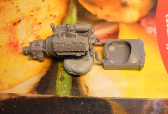
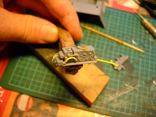
So, if armoured cars are your thing, pull up a chair and follow along. Questions or comments are encouraged and welcome. I will try to keep a steady stream of WIP photos and observations coming.

Kimmo
russamotto
Visit this Community
Utah, United States
Joined: December 14, 2007
KitMaker: 3,389 posts
Armorama: 2,054 posts
Posted: Monday, May 12, 2014 - 12:30 AM UTC
I'll be watching. I have started construction of mine, which is going very slowly at the moment.
Thudius
Visit this Community
Uusimaa, Finland
Joined: October 22, 2012
KitMaker: 1,194 posts
Armorama: 1,077 posts
Posted: Monday, May 12, 2014 - 01:30 AM UTC

Quoted Text

I'll be watching. I have started construction of mine, which is going very slowly at the moment.


I just started gluing, slow going sounds about right.

Kimmo
Thudius
Visit this Community
Uusimaa, Finland
Joined: October 22, 2012
KitMaker: 1,194 posts
Armorama: 1,077 posts
Posted: Monday, May 12, 2014 - 01:48 AM UTC
As alluded to, the going may be a little slow with this kit. I figured I'd start with the chassis, it's a multi piece affair and the locating pins are rather tiny. I wanted to get this all lined up nice and square as possible to make sure the body sits nice and that the wheels all touch the ground.

Cleaning up the various parts posed no real problems, some of the attachment points are in delicate areas so be very careful removing parts. I found it easier to not snip too close with the side cutter and then clean up the nubs with a scalpel or razor blade. Mark your cross members so you don't get them mixed up and pay very very very close attention to the instructions. The plastic is on the soft side so use a fresh blade and trim carefully. I sanded the locating pin on the transfer case for a better fit, also take note which way parts F11 and 13 align, you get a better view in Step 26.


Glue the little wings (F 24/25 and Ca 10/11) to their respective braces, the fit is pretty good so you don't have to fiddle too much here. Do not glue part B41 (the first cross brace) until last and watch how it mounts to the chassis. Mark the locating pins to aid in lining up the slots. Do one side first, let set for a bit, then flip it over and glue the back cross members first. Again, let dry a little, then do the forward ones. Make sure you leave clearance for the drive shaft.


I checked to see that everything was more or less square with the cutting mat as a guide, then clamped the assembly to my sanding block. I left off the rear springs and mounts for now as they can be added later.


While that sets, I'll work on the engine.

Kimmo

Thudius
Visit this Community
Uusimaa, Finland
Joined: October 22, 2012
KitMaker: 1,194 posts
Armorama: 1,077 posts
Posted: Monday, May 12, 2014 - 05:18 AM UTC
The engine went together reasonably well, small parts notwithstanding. There was a bit of a gap to deal with for B14, perfect putty was brushed in and wiped down with a cotton bud then a coat of primer to check the seam. Parts B16/17 don't have locating pins so watch alignment. Be careful with parts B47 and B50. Removing the two attachment points of B50 is tricky and I'd recommend attaching it to the fan belt assembly before gluing the belt assembly to the engine proper. It's a tight fit so be very careful it doesn't go flying. The rear housing (B51) will fit better if you slightly enlarge the hole. The instructions are a little vague on what the orientation of it is so I attached mine with the switch(?) pointing to the right. I left the fan and filter off for the time being, I'll pain the engine first and then glue those on.


I got started on the radiator as well. The rear cover has some unfortunate attachment points at the thinnest part of the cover. Do not attempt to trim these until it's been glued to the front piece. There's also a couple of nasty ejector pin marks, these might be hidden but trim and fill to be on the safe side. I should have consulted the refs before I glued, hopefully the back side of the radiator screen won't be visible once the fan is blocking the opening.


This is as good a place as any to stop for the day. Hopefully I'll get some more bench time tomorrow.

Kimmo
russamotto
Visit this Community
Utah, United States
Joined: December 14, 2007
KitMaker: 3,389 posts
Armorama: 2,054 posts
Posted: Monday, May 12, 2014 - 09:02 AM UTC
It looks very good. I do wish the instructions were more clear on placement with some items (almost every kit has this issue) Even though the plastic is soft, I also found it brittle. A sharp knife and good magnifiers are most certainly needed.
VintageRPM
Visit this Community
Texas, United States
Joined: November 28, 2010
KitMaker: 300 posts
Armorama: 207 posts
Posted: Monday, May 12, 2014 - 09:17 AM UTC

Quoted Text


I'll be using whatever references I could source from the internet, sadly there isn't much. There is a book available that by all accounts is quite good and useful https://armorama.kitmaker.net/news/13846


Excellent book. Available in the US from Squadron and Amazon. (Not an inexpensive book, but about $20 cheaper at Amazon.)
Thudius
Visit this Community
Uusimaa, Finland
Joined: October 22, 2012
KitMaker: 1,194 posts
Armorama: 1,077 posts
Posted: Monday, May 12, 2014 - 11:54 AM UTC
Russ, haven't had any brittle issues yet, but it does feel as if the plastic might peel if you dig deep with the blade.

Mike, I wish I could buy every book published

Kimmo
Thudius
Visit this Community
Uusimaa, Finland
Joined: October 22, 2012
KitMaker: 1,194 posts
Armorama: 1,077 posts
Posted: Tuesday, May 13, 2014 - 12:35 AM UTC
Slight update and a mea culpa, should have studied the instructions a little better. Parts Ce9 do not go into the chassis frame but on top. Step 24 is vague on this but it is apparent in Step 25. Fortunately I was able to remove the parts. A little clean up will be necessary. An interesting side note: the glue had not fully cured even though it had been applied yesterday. Something to bear in mind if you absolutely need to make sure a bond has cured.


Moving on to the rear axle, I cleaned up the leaf springs. Tedious. Be careful removing them from the sprues and in cleaning off the attachment points. There are actually locating stubs on the top of the spring. I removed mine accidentally and made attachment a little trickier than need be. I wish manufacturers would stop putting attachment points on mounting stubs. Very annoying and the potential for problems just increase. Right, next rant.

The axle and transfer case are in four pieces, the axles do not have keyed stubs meaning you have to eyeball the alignment. If you shave the leaf spring stubs off like I did, you now have to fiddle that much more to get everything aligned. Some fiddling is unavoidable here in any case. I would almost recommend gluing the axles to the leaf springs and then glue that assembly to the frame rather than the sequence indicated in the instructions. The drive shaft is also a little fiddly. The instructions have a slight error with F15, it actually goes onto the cross frame and not the transfer case as shown. The picture showing it installed is correct. Pay close attention to the way the holes line up for F15 and B46 and the drive shat stubs. The longer stub on the drive shaft points forward, it is a little unclear in the instructions. Do not try to remove parts F3/4 while they are still on the sprue, cut the entire sprue loose and then chop them off.


I moved on to the wheels so the suspension could sit and dry. The tires have very thick attachment points, don't try to chop them off, you'll just run the risk of damaging something. Shave the points down, then chop.


Check that the rims sit in deep enough. I found a quick run of my fingernail on the mating edge gave a better fit. I also scraped the mold lines on the spare wheel cutouts, they shouldn't be seen on the main tires.


That's it for today, more tomorrow. Knock on wood.

Kimmo
djohannsen
Visit this Community
Virginia, United States
Joined: June 24, 2005
KitMaker: 364 posts
Armorama: 355 posts
Posted: Tuesday, May 13, 2014 - 01:34 AM UTC
Very enjoyable so far; thank you. With an ever growing interest in both the North African campaign and in armored cars, I'll be continuing to follow this build.
Thudius
Visit this Community
Uusimaa, Finland
Joined: October 22, 2012
KitMaker: 1,194 posts
Armorama: 1,077 posts
Posted: Tuesday, May 13, 2014 - 05:32 AM UTC
Thanks Dave. Always nice to have another happy customer.

Kimmo
Thudius
Visit this Community
Uusimaa, Finland
Joined: October 22, 2012
KitMaker: 1,194 posts
Armorama: 1,077 posts
Posted: Wednesday, May 14, 2014 - 03:09 AM UTC
No bench time today, but I did get notice that some nice photo etch is heading this way. Looks like the build just got a little more detailed. While I wait for it to come in, I'll mainly do parts clean up so things might be a little dull for a while as far as updates go. This will give me a chance to go over references and planning.

Kimmo
Thudius
Visit this Community
Uusimaa, Finland
Joined: October 22, 2012
KitMaker: 1,194 posts
Armorama: 1,077 posts
Posted: Thursday, May 15, 2014 - 06:09 AM UTC
Continued with the suspension, engine and got started on the radio. I also filled in the hairline seam on the tires. Using thinned down Perfect Putty, I brushed it into the seam and then removed the excess with a moistened stiff stipple brush. This stuff is great for these kinds of applications where there is a lot of detail that might get damaged using solvent based putty.


I did the front suspension next. Just like the rear, it's a multi piece affair. I had to sand down the stub on the leaf spring for a better fit and then clamped it. As that was setting, I cleaned up the drive shaft and mounts. The transfer case had managed to come loose during the last session which turned out to be a good thing as I was able to get the shaft to line up nicely. So, if you haven't already glued it in place, leave it off until you install the shaft. I added some sliced rod to the universal joints, they got shaved off because the sprue attachment points were there, again. I left off all linkages and brake drums as with rear, I'll add them later. I also added a few pieces here and there and did some filling.


The engine got some work, starting with thinning the fan belt by scraping the inner edges. I did the upper runs only, I don't think the bottoms will be seen.


Next, the coolant hoses were glued in place on the engine only. Align them by eye, let the glue dry for a few minutes, then use the radiator to check alignment and set aside to dry some more.


When that had all set, I added the exhausts. 3 separate pieces here, so you will have some fiddling. It wasn't as bad as I expected. Use these photos as guides for how they sit. I plopped the engine in place and everything seemed to be where it should be. I'll let that dry overnight and then fill in seams and sand. The muffler and tail pipe will go on later.


Turning to the radio, I decided to add some detail. First off, the handles got replaced with wire. The molded on solid handles were very very carefully removed, then holes drilled for the wire. The instructions are a bit vague on how the set up sits on the shelf, so I used the refs listed at the start of the blog as an aid, and made some judgement calls.

Glue the connector cable Ca3 first, then a strip of 20 thou under the radio units to bring them up as per photos. Ca2 should have another connector C10 to be more accurate. I had already glued it in place so just turned the box around. The shelf needs sanding to get the unit to sit flush. Either the shelf is too small, or the units are all oversized a touch. Maybe a bit of both. I added the cable connecting Ca2 to the main radio with 2 Mbit cable. Protip: make friends with telecoms engineers. It worked easily because it has a core and sheath. Just drill holes into both C10s and fit the wire.


And that's where we sit for now. I should get more time tomorrow and Saturday.

Kimmo
Thudius
Visit this Community
Uusimaa, Finland
Joined: October 22, 2012
KitMaker: 1,194 posts
Armorama: 1,077 posts
Posted: Saturday, May 17, 2014 - 04:19 AM UTC
Didn't get any time in yesterday after all, funny how life interferes with modelling. Today I continued with the suspension. The front steering assembly is a tricky little step that should be explained better in the instructions. It is designed so that the wheels can rotate and be positioned to show them turning. Almost.

Right, Ce 10/11 are ball mounts that get trapped between Ce15/Ce14 and F17/F18 respectively. Cleaning up the balls are fun. Trust me. Fit the parts together and run a little glue on the outside edges so that none gets on the ball. Easy enough. Ce7/Ce8 are glued on the flats of Ce15/14. C1s are trapped between C2s and F17/18. Sand C1 to make sure it rotates freely. Dry fit, then apply glue to the outside edges. After these assemblies have dried a bit, then attach to the axles. This sounds complicated, but is pretty straight forward when you get going. As you remove pieces, orient them as shown on the instructions to keep parts on the correct side, dry fit everything and consult the instructions and photos below.


Now the linkage arm. This is where you need to think ahead, or do some minor surgery. Not having done anything like this in years, I assumed the linkage arm would swing with the wheel disk thingies. Very technical term. Of course it doesn't.


To make it swivel, you will need to drill through the joints and shafts and insert a pin, or just glue the wheel mounts at whatever angle you wish, then install the arm.


The rear wheel mounts are fairly simple. Glue C3 to C5 trapping C4 in between. Careful with the glue. Sand C4 a bit to make sure it rotates and sits in the recess.

I dry fit the tires to see if everything is more or less level, so far so good.


While all that was drying, I started on the body. The floor plate needs a few nasty ejector pins removed, they looked to interfere with a cross frame. Don't worry about the other ejector marks apart from the ones in the wheel wells, just make sure they aren't sitting proud.


I glued in the parts in step 29 except for B15 and cleaned up the hull sides and taped everything together to check fit. Be careful removing stubs from the hull sides and pay attention to the bevels. The front has some very thin edges and there are a few ejector marks to deal with. The fit appears to be quite good and no warped parts were evident other than the rear left fender well on the floor pan. This area is the only part that bothers me, it's a butt join to the hull side, care will be needed here.


I decided to also check the fit of the firewall and to see how much room I have for adding details in the engine compartment.


I did some other clean up etc. I think I can get away with adding the interior detail after the sides are glued up. I dry fit the roof too and it looks to sit well enough. I'm slightly worried about what the interior join will be like. It will be tough to fix so extra care and attention will be needed. As I wait for the pe to arrive, I'll start on detailing the engine compartment. I can't really do too much more until I see what the pe includes so stay tuned and I'll update as we go along.

Kimmo
russamotto
Visit this Community
Utah, United States
Joined: December 14, 2007
KitMaker: 3,389 posts
Armorama: 2,054 posts
Posted: Saturday, May 17, 2014 - 06:05 AM UTC
It looks really nice. I haven't gone that far with my build. It will be good to have this as a reference.
Thudius
Visit this Community
Uusimaa, Finland
Joined: October 22, 2012
KitMaker: 1,194 posts
Armorama: 1,077 posts
Posted: Saturday, May 17, 2014 - 06:33 AM UTC

Quoted Text

It looks really nice. I haven't gone that far with my build. It will be good to have this as a reference.


Thanks Russ. That's why they pay me the big bucks: to go out and get shot at

Kimmo
Robbd01
#323
Visit this Community
Arizona, United States
Joined: February 13, 2013
KitMaker: 791 posts
Armorama: 344 posts
Posted: Saturday, May 17, 2014 - 06:42 AM UTC
Sweet a build review. I ordered mine a week or so ago off of ebay and it is coming from Poland. I also ordered the book "Marmon-Herrington - A History of the South African Reconnaissance Car". I will sit back and watch and learn from this post

Cheers
Thudius
Visit this Community
Uusimaa, Finland
Joined: October 22, 2012
KitMaker: 1,194 posts
Armorama: 1,077 posts
Posted: Saturday, May 17, 2014 - 08:26 AM UTC
Thanks Robbie. It may jump around a little and it will have some bells and whistles thrown in, but you should get a good idea of what you'll get in the box. I was going to do OOB until I found out I was getting all that lovely brass stuff to play with. Now we get 2 reviews in one go, 3 if both sets are in the mail.

Kimmo
C_JACQUEMONT
Visit this Community
Loire-Atlantique, France
Joined: October 09, 2004
KitMaker: 2,433 posts
Armorama: 2,325 posts
Posted: Saturday, May 17, 2014 - 08:07 PM UTC
Very interesting build and tips, thank you!

I saw one built up and painted at a model show last week, and it looked excellent, with all hatches door open, etc... Makes me want to get and build one, maybe the turretless "beute" Afrikakorps variant.

Cheers,

Christophe
Thudius
Visit this Community
Uusimaa, Finland
Joined: October 22, 2012
KitMaker: 1,194 posts
Armorama: 1,077 posts
Posted: Saturday, May 17, 2014 - 11:10 PM UTC
Thanks Christophe. It certainly is different from the usual line up of panzers and Shermans. Not exactly a weekend kit, but I'm impressed enough so far with the detail and fit.

Kimmo
AlanL
Visit this Community
England - East Anglia, United Kingdom
Joined: August 12, 2005
KitMaker: 14,499 posts
Armorama: 11,675 posts
Posted: Saturday, May 17, 2014 - 11:42 PM UTC
Hi Kimmo,

Excellent looking build, you're making good progress.

Al
Thudius
Visit this Community
Uusimaa, Finland
Joined: October 22, 2012
KitMaker: 1,194 posts
Armorama: 1,077 posts
Posted: Sunday, May 18, 2014 - 12:10 AM UTC
Thanks Al. The suspension and engine does take it's sweet time getting done. The rest should go a lot quicker, even with some extra details thrown in.

Kimmo
Thudius
Visit this Community
Uusimaa, Finland
Joined: October 22, 2012
KitMaker: 1,194 posts
Armorama: 1,077 posts
Posted: Monday, May 19, 2014 - 05:45 AM UTC
More parts clean up and delving into the photo etch that comes with the kit. Did some work in the rear compartment, nothing dramatic here. The instructions for parts A9/10 are a bit vague, but I think I got them right. The pe brackets for the radio fold up easily enough. The U bracket has a slight booboo in that there aren't any bends marked for the upper bend. Find the mid point, and measure 1.5mm on either side, score lightly and you have bending guides. Use the radio shelf as an aid to align stuff. For the battery boxes, I ended up using stretched sprue, I'll save the brass wire for something more useful. The instructions are again slightly vague on placement so I glued the sprue above the hinges on the side, then the pe strap. The strip for the rear seat cushion went on well enough. I didn't use super glue, just regular liquid cement for all the pe pieces. If you haven't tried this, do so. Brush on some glue where the part will sit, place, and touch the brush to the part. Let it sit for a few seconds to let the glue soften the plastic and press in. Works quite well.


Now to the day's fun stuff. The kit supplied dashboard lacks dials or decals for the dials. The Part pe sets don't appear to address this either so you have a few choices: scrounge some decals, hope someone makes a pe set, paint/scribe the dials. I don't have any appropriate decals available, so here's what I came up with.

I took the dash from Eduard's mortar carrier set that was laying about (it has the correct multi dial), then chopped, scraped/filed unwanted detail away, then trimmed and glued the pieces onto the film (which was also chopped accordingly) and a new backing made from 5 thou sheet. I also used the 5 thou to fill in some blank spots that the pe dash didn't cover. I gave it a coat of primer and it looks pretty good. I'll need to do some sanding/scraping to get everything nice and level. More photos to come.


It's not 100% accurate, but it should look authentic enough. I'll also do up the kit supplied dash with some aircraft dials I have to show you another alternative.

Kimmo
Thudius
Visit this Community
Uusimaa, Finland
Joined: October 22, 2012
KitMaker: 1,194 posts
Armorama: 1,077 posts
Posted: Tuesday, May 20, 2014 - 01:32 AM UTC
Cleaned up the dash and gave it some more primer to level things out. I added the "wings" from scraps that were glued and then shaped. Looking at the refs, it seems there's actually a glove box on the left side. I'll need to think about that one. Drilled holes for the knobs which I'll make from stretched sprue. The kit supplied ones look more like dials.


Added the missing pieces to the radio apart from the cage, that will go once the interior is more or less done. It's very fragile looking so I don't want to damage it. You get some very teeny tiny pieces to work with, the microphone mouth piece will go flying if you're not careful. Glue the handle first, then plop the mouth piece in place. If you're worried about trimming the piece, glue it on and then go at it with a sanding stick or file when the glue has dried.

The head phones are an accident waiting to happen if you don't think ahead and take a few steps to make life easier. First off, separate the headphone sprue rather than try to remove them as is. They will launch into the abyss, guaranteed. Since I have a wired up set, this made it a little easier. I drilled holes in the headphones while on the sprue and glued in lengths of wire, then removed them from the sprue and trimmed the attachment point. I couldn't be bothered to attempt to clean it up any better than a close shave. The headset is supposed to go into holes in the headphones (unless IBG seriously thinks that something smaller than a pin point is a good attachment idea), alas, no hole. So, two options: drill holes (a sewing needle will work) or do what I did. Bend the attachment points flat so that the head strap ends up looking like an omega. Glue each earpiece onto the radio, using the head strap as an alignment guide, then glue the head strap to the trimmed points on the ear pieces. A drop of glue secures the strap to the radio.


As you can see, I also did the rest of the wiring. The headphones and mic are the same wire I used earlier with a slice of sheathing as the jack plug glued into drilled holes. I also added the power cable to a rounded piece of rod. Bend everything to taste and presto, one wired radio. The rear shouldn't be visible so you can cheat with some of the cables.


I gave everything a coat of primer and will need to go back and blend in some of the cable joins. The face detail is really excellent and will certainly pop if painted nicely. I love a challenge. Hopefully more tomorrow.

Kimmo
Malvin
Visit this Community
Severocesky Kraj, Czech Republic
Joined: October 18, 2013
KitMaker: 111 posts
Armorama: 101 posts
Posted: Tuesday, May 20, 2014 - 01:41 AM UTC
Black Dog will issue accessories set the following news.
Malvin
vt-models.cz
 _GOTOTOP