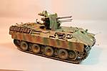
Here's my first update.After I open the box,I lay out the sprues and look at the instructions to make sure I've got everything.
I mark my sprues with masking tape to make it easier to find them like this In this case there where only 2 sprues so I didn't bother.
The first thing I saw was that the the one piece tracks where pretty warped
So I weighted them down and let them set overnight
This is not a Tamiya advert,they just fit the bill
After looking at the instructions,I started with the lower hull assy.The detail in this kit is pretty good,but there is alot of flash.Hence my next challange.See the injector pin flash?It runs the full width of the side hull parts I ended up using my dremel tool to remove most of the pins and a 600 grit wet sanding stick to final finish
I found that the plastic in this kit is really greasy and was clogging my dry sanding sticks.Thats why I wet sanded the parts.I make all my wet sanding sticks.If you guys would like to see how just let me know,and I will post pics and instructions.Thats all for now.Jeff T.
Campaigns
Where Armorama group builds can be discussed, organized, and updates posted.
Hosted by Darren Baker, Richard S.
Panther Campaign
imatanker
Maine, United States
Joined: February 11, 2011
KitMaker: 1,654 posts
Armorama: 1,565 posts
Joined: February 11, 2011
KitMaker: 1,654 posts
Armorama: 1,565 posts
Posted: Tuesday, February 07, 2012 - 12:24 PM UTC
Posted: Wednesday, February 08, 2012 - 07:55 PM UTC
Panthoholics,
Well after almost a month from my last posting I’m back with the first part of a photo-etch update. Aside from painting dealing with photo-etch (PE) metal parts is where I get a little bogged down in my builds because I haven’t enough experience with using PE parts. It’s now becoming as common as water-slide decals to have PE metal parts included in most armor kits. And unlike plastic parts, PE metal parts require different building methods, bonding mediums and tools to assemble. Most current PE metal parts are produced from brass and this is the medium that I’m going to be using on this build. In case you’re interested, I’ve included a link to a Scale Model Guide.Com article entitled Model Kit Materials describing this medium, its process and characteristics as used from our modeling viewpoint. If you do happen to check out the article you’ll find the topic on PE parts around the middle of the page. Well, lets see what we got here . . .
The fabricated styrene sheet armor antenna base plate with its three bolts shown fixed in place on the antenna base. I also fitted a section of the crew compartment heater (C21 + D18) over the opening on the left side radiator armor deck plates. The six small lifting hooks (A3), in step 9 of the assembly instructions, on the right and left side radiator armor deck plates had previously been installed and I let mention of them slip by me on the last posting, oops!
The first photo-etch (PE) part that I installed was the screen that resides under the armor air intake deflector on the armor rear deck plate. I used the kit supplied PE armor air intake deflector screen (MA3) because the Voyager Model (VM) photo-etch screen was too small in diameter for the opening on the kits rear deck plate. The screen on the real vehicle is actually sandwiched between the rear deck plate for the air intake and the armor air intake deflector flange. I used a drill under the armor air intake deflector flange to thin it down to scale and allow the screen to sit up closer to the flange.
A combination of VM and kit supplied PE parts were used to assemble the screens for the cooling air intake armor guards. I used the VM screens on all four of the cooling air intake armor guards. The sliding shutters on the real vehicle were made up of a pair of shutters, a fixed shutter (top) and movable sliding shutter (bottom). These sliding shutters were introduced on late model Panther Ausf. G’s and was used on the right side of the vehicle to regulate air intake and would have been installed on the Ausf. F. What I did was place the kit supplied PE movable sliding shutters (MB34 + MB35 x 2) over two of the cooling air intake armor guard screens that would be fitted to the right side of the vehicle. Here’s where things get a little tricky, so pay attention! The assembly instructions don’t tell you or show you that the movable sliding shutters should be placed at opposite ends on each of the two cooling air intake armor guards. There is a section of panel on the movable PE shutter that runs the width at one end of the shutter that needs to be folded up at 90° (red arrows). This panel was used to assist the crewmembers with closing, opening or leaving the movable sliding shutter somewhere in-between and should be installed opposite each other on the two cooling air intake armor guards. Thus, the cooling air intake armor guard that resides closest to the front area on the right side of the rear deck should have the movable sliding shutter panel protruding through the top fixed shutter on the right side and the cooling air intake armor guard that resides closest to the rear on the rear deck should have the movable sliding shutter panel protruding through the top fixed shutter on the left side. You got it Toyota?
The kit also supplies you with a pair of closed shutters (A27) in plastic should you choose not to use the PE parts and a pair of open fixed shutters (A29) in plastic to use or not use with the kit supplied PE movable sliding shutters mentioned above. These shutters also have a different type of locking mechanism, molded onto the plastic, to secure the movable sliding shutter. I chose to go with the VM fixed shutters.
All four of the cooling air intake armor guards with their respective screens and sliding shutters have been installed in their proper locations. If you’ll look closely you’ll see that I have added all of the cap screws for securing the screens and sliding shutters to the two cooling air intake armor guards that reside nearest the rear deck. And only one cap screw is installed on each of the other two cooling air intake armor guards located closest to the front area of the rear deck (more PE parts to be fitted later to these two grates). Ten of these cap screws are found on each of the two ‘A’ sprues for a total of 20 cap screws; they are located on one side of the sprue trunk that runs between parts A20 and A33. Of course, there is no mention as to where these cap screws are to be placed or used on the kit, however you can just see them on the parts location sprue tree diagram on the first page of the assembly instructions.
The engine access hatch and armor air intake deflector were installed to the rear armor deck plate and this completed sub-assembly from step 8 was then cemented into its location on the center rear of the upper chassis. The other section of the crew compartment heater (D12) was then cemented into place. I used a combination of kit and VM parts to complete the crew compartment heater; these included the exhaust screen frame (D6) and the VM exhaust screen and screen frame. In order to get this combination of parts to fit together I had to carefully file down the inside diameter of the plastic exhaust screen frame to fit the VM parts. Between the filing and check fitting of these components it took some time to do but I like the results. Finally the cooling air exhaust armor guard with the VM exhaust screen was cemented to its location over the opening on the right side radiator armor deck plates.
As I had mentioned earlier there were two different type of locking mechanisms to secure the movable sliding shutters and I went with the most common type, that being the butterfly fasteners. I used a pair of the Bronco Models German butterfly wing nuts on the fixed portion of the sliding shutters on the end where the protruding movable sliding shutter panel is located (indicated in the red circles).
Two of the VM pie-slice panels were added to the crew compartment heater and secured with a .010” (0.254 mm) thick styrene disk, made from a punch and die set, this was topped off with a .030” (0.762 mm) diameter styrene hex rod. The remaining pie-slice panels were fixed to their stowage location on the outside of the crew compartment heater and the VM securing straps for these pie-slices were fixed over them with a dowel pin made from a piece of .020” (0.508 mm) diameter styrene rod. A small VM chain was added to the top portion of the dowel pin and the other end of the chain was secured to the top of the crew compartment heater per the Jentz & Dole references. An RB Models (brass) rubber insulated antenna mount for the 2 m antenna was fixed to the armor antenna base plate (inset photograph).
Two VM brackets for holding the end of the towing cable were fixed to their respective locations on the rear of the upper deck. I cut away the mounting end of the fuel vent line (C14 – red arrow) and mated that to a .020” (0.508 mm) diameter bent brass rod and added it to the VM vent line guard. This assembly was fixed to its proper location on the right rear corner of the upper deck.
Here are the items and tools that I used for applying the PE parts to the model. Most experienced modelers are already armed with most of this stuff, but for those that aren’t I’ll go ahead and mention a little about some of them here. On this first PE update I extensively used a gel type of superglue (bSi IC – Gel) and unlike the more common type of liquid superglue this glue allows me a small amount of time to move parts into position before the glue bonds the part against the area you placed it on. Gator’s glue is an acrylic based glue and can be washed off with water. This glue is strong once it sets up and from my experience it works best on PE parts, such as the screens and smaller items, that won’t have any stress placed on them, like working tool clamps. Also, for the just mentioned parts and not pictured, is clear lacquer based finger nail polish (unless you’re working on a model don’t let your wife or girlfriend catch you with a bottle of this stuff in your possession).
In a few instances where the glue got into appearance areas or oozed out from under parts I was able to remove the gel or liquid superglue with a cotton tipped swab lightly moistened in Acetone. For getting the swabs into really tight areas I use a cosmetic multi-purpose cotton applicator, sold in most large drug stores such as Wal-Greens, CVS, Rite-Aid, ect. Depending on the brand of swabs, you can also pinch the end of the cotton tipped swap with a pair of flat nosed pliers to thin the end of the tip and could even cut them to shape with a pair of cutters or scissors and they will usually hold their shape after moistening them with Acetone. Just remember to keep the swab lightly moistened, as the acetone can easily mar and soften plastic and remove paint. Lightly brush away at the gel or super glue until you’ve removed or blended it into the surrounding area. For the acrylic glue just wait a bit until the glue begins to set up and remove it with a toothpick or needle. A tiny amount of any of the glues placed on a piece of wax paper, taped to a flat surface, I use a piece of glass, will allow you to use the glue for one modeling session before the glue begins to set up. A sewing needle inserted to the end of a drilled out toothpick and secured with superglue serves as an applicator for the glues and a Micro-Brush for the superglue accelerator.
I place the PE fret against a small piece of styrene sheet to remove parts from the fret using either the tip of a flat # 11 or round # 10 X-Acto blade or the micro chisel on a flat piece of wood for the thicker made PE parts. A set of flat edged tweezers is used for trimming off any left over fret material from the part followed by a medium grit sanding stick. For handling PE and bending some of the really small parts I use flat round edged tweezers such as those used by stamp collectors. Did I mention safety glasses and a well-ventilated area?
I’ve said enough about tools here and hopefully the photograph above has conveyed some of that idea to you? Next up are the fenders, a little soldering, more tools, some useful article links on PE and IMHO a must have DVD. It’s late now so I’ll return again this week to address and make comments on the ongoing builds here.
~ Eddy
Tojo72
North Carolina, United States
Joined: June 06, 2006
KitMaker: 4,691 posts
Armorama: 3,509 posts
Joined: June 06, 2006
KitMaker: 4,691 posts
Armorama: 3,509 posts
Posted: Thursday, February 09, 2012 - 07:02 AM UTC
Eddie,that PE work is meticulous,looks great
imatanker
Maine, United States
Joined: February 11, 2011
KitMaker: 1,654 posts
Armorama: 1,565 posts
Joined: February 11, 2011
KitMaker: 1,654 posts
Armorama: 1,565 posts
Posted: Saturday, February 11, 2012 - 04:17 AM UTC
Gentlemen,I'd like to hang some track links on my 1/76 Jagd.Does any one make Indy links?And if not,does anyone have a few they would like to donate to the cause?Jeff T.
asmodeuss
Quebec, Canada
Joined: November 19, 2011
KitMaker: 1,389 posts
Armorama: 1,388 posts
Joined: November 19, 2011
KitMaker: 1,389 posts
Armorama: 1,388 posts
Posted: Saturday, February 11, 2012 - 09:19 AM UTC
Hi all! I've completed a couples of steps today.
It went pretty strait forward I am pleased with the quality of the kit no complaints for now.
I've let the last of the supension arm unglued so I can adjust the idler wheel for sag (waitting for the fruil tracks I've ordered this morning )
Then there was confusion with the pe on the plan, I was pretty nervous since I've never done pe before.
I can assure you it is not ma3!
Realising that I had to fold tiny pieces of brass I scratched a tool with leftover plexiglass.
asmodeuss
Quebec, Canada
Joined: November 19, 2011
KitMaker: 1,389 posts
Armorama: 1,388 posts
Joined: November 19, 2011
KitMaker: 1,389 posts
Armorama: 1,388 posts
Posted: Saturday, February 11, 2012 - 09:27 AM UTC
Voila my first PE fold and assembly!
I've also bored the exhaust pipes
The jack went well. Cutting the plastic rack arms of it was quite easy but the PE rack will be a challenge. Looking forward to it.
Thanks for your comments.
Phil.
I've also bored the exhaust pipes
The jack went well. Cutting the plastic rack arms of it was quite easy but the PE rack will be a challenge. Looking forward to it.
Thanks for your comments.
Phil.
asmodeuss
Quebec, Canada
Joined: November 19, 2011
KitMaker: 1,389 posts
Armorama: 1,388 posts
Joined: November 19, 2011
KitMaker: 1,389 posts
Armorama: 1,388 posts
Posted: Saturday, February 11, 2012 - 11:00 AM UTC
I had the most trouble finding how and where to glue the jack rack, the instruction are very confusing regarding the emplacement of th PE rack. Looking at the art on the box I finnaly took a decision.
If someone has info or image on the real thing I would apreciate. I have not been able to find a visual reference in books or web.
Thanks
Phil
If someone has info or image on the real thing I would apreciate. I have not been able to find a visual reference in books or web.
Thanks
Phil
BBD468
Texas, United States
Joined: March 08, 2010
KitMaker: 2,465 posts
Armorama: 2,383 posts
Joined: March 08, 2010
KitMaker: 2,465 posts
Armorama: 2,383 posts
Posted: Saturday, February 11, 2012 - 11:25 AM UTC
Hi Phil,
your off to a great start. nice touch on the exhaust tube. dragon/cyber-hobby kit instructions can be very confusing. some times items or part numbers are just missing. its good to have as much reference material you can for just such occasions as well as this forum to ask questions. looking forward to your build!
Hey Eddy,
Yours is comeing along nicely. the serial numbers are a sweet addition to that bad boy!
Gary
imatanker
Maine, United States
Joined: February 11, 2011
KitMaker: 1,654 posts
Armorama: 1,565 posts
Joined: February 11, 2011
KitMaker: 1,654 posts
Armorama: 1,565 posts
Posted: Saturday, February 11, 2012 - 12:29 PM UTC
Phil:that looks nice so far.As for pictures, have you tried Prime Portal?It's a great site with lots of pics.I had to use it today after I discovered my kit did not come with the front fenders and I needed to see what they looked like and how they attached.
Great job on the PE jig.You could have started your PE career with a little bit bigger peice though
Jeff T.
Great job on the PE jig.You could have started your PE career with a little bit bigger peice though
Jeff T.
asmodeuss
Quebec, Canada
Joined: November 19, 2011
KitMaker: 1,389 posts
Armorama: 1,388 posts
Joined: November 19, 2011
KitMaker: 1,389 posts
Armorama: 1,388 posts
Posted: Saturday, February 11, 2012 - 12:38 PM UTC
Quoted Text
Phil:that looks nice so far.As for pictures, have you tried Prime Portal?It's a great site with lots of pics.I had to use it today after I discovered my kit did not come with the front fenders and I needed to see what they looked like and how they attached.
Great job on the PE jig.You could have started your PE career with a little bit bigger peice though
Jeff T.
Thank you Jeff. I'll make sure to add prime portal to my fav.
As for the small piece: Indeed it was small and it was even smaller yet when I droped it on the floor! Took me half an hour to find it
imatanker
Maine, United States
Joined: February 11, 2011
KitMaker: 1,654 posts
Armorama: 1,565 posts
Joined: February 11, 2011
KitMaker: 1,654 posts
Armorama: 1,565 posts
Posted: Saturday, February 11, 2012 - 01:19 PM UTC
Quoted Text
Quoted TextPhil:that looks nice so far.As for pictures, have you tried Prime Portal?It's a great site with lots of pics.I had to use it today after I discovered my kit did not come with the front fenders and I needed to see what they looked like and how they attached.
Great job on the PE jig.You could have started your PE career with a little bit bigger peice though
Jeff T.
Thank you Jeff. I'll make sure to add prime portal to my fav.
As for the small piece: Indeed it was small and it was even smaller yet when I droped it on the floor! Took me half an hour to find it
Dude,I feel your pain been there many times.Welcome to the wonderfull world of PE.Jeff T.
imatanker
Maine, United States
Joined: February 11, 2011
KitMaker: 1,654 posts
Armorama: 1,565 posts
Joined: February 11, 2011
KitMaker: 1,654 posts
Armorama: 1,565 posts
Posted: Saturday, February 11, 2012 - 11:20 PM UTC
O.K. Welcome to Week End Update.After getting the hull sides trimmed and ready to go,I desided after looking at the instructions to assemble the hull,in this case it was the first step in the guide.This is not always the case with Me as sometimes I jump around making sub assemblies first,depends on the kit.I used some tape to hold the parts in place while the glue dried and to keep the hull square
You can see that the front seam is going to need some filler
I spend alot of time trimming and dry fitting the hull parts.They need to fit well for the rest of the kit to turn out well.
After I finish a step,I mark my instructions,to help me remember what I've done.I'm old you know When I'm done with a step I use a red pen to scribble out the step number.If I have to return to a step,like to help with painting or assembly I put a red X on the step number and circle it and the part to be installed or painted later with blue,Then when done I scribble out the step number.Is that clear
Back to the hull.Front seams filled......
And sanded Thats all for now.Dry fitting the roadwheels and tracks will be next I think.Jeff T.
Eddy:your build is looking good.Thanks again for the help with my other project.
asmodeuss
Quebec, Canada
Joined: November 19, 2011
KitMaker: 1,389 posts
Armorama: 1,388 posts
Joined: November 19, 2011
KitMaker: 1,389 posts
Armorama: 1,388 posts
Posted: Sunday, February 12, 2012 - 02:44 AM UTC
Hi Jeff, nice update I like the way you keep track of things you have done. What product do you use to fill th seems?
Thank you
Phil.
Thank you
Phil.
cacciacarri
Rimini, Italy
Joined: March 18, 2007
KitMaker: 91 posts
Armorama: 88 posts
Joined: March 18, 2007
KitMaker: 91 posts
Armorama: 88 posts
Posted: Sunday, February 12, 2012 - 05:33 AM UTC
Hi Everyone,
Finally I am starting my Dragon Panther A late.
Here some initial progress:
I jointed the two 'lower hull' parts,glued drive sprockets and others little particulars
I have just to fill gap
other side
zimmerit on the rear side and stowage bins I have just to finish off with epoxy putty
zimmerit front side I need to sanding some bulges.
I removed them for better gluing the zimmerit sheet.
cheers
Antonio
imatanker
Maine, United States
Joined: February 11, 2011
KitMaker: 1,654 posts
Armorama: 1,565 posts
Joined: February 11, 2011
KitMaker: 1,654 posts
Armorama: 1,565 posts
Posted: Sunday, February 12, 2012 - 10:59 AM UTC
Quoted Text
Hi Jeff, nice update I like the way you keep track of things you have done. What product do you use to fill th seems?
Thank you
Phil.
Phil:The instruction thing works for me.With this kit is was not really all that important since there where not that many parts or steps.Where it really works is with the bigger 1/35 kits.
What I use to fill the seams is an automotive product called Cargroom Glazing and Spot Putty.It works nicely on larger scale kits,but is not quite fine enough for 1/76.If I keep building the small stuff,I will have to find something else.As you can see it did work out O.K.
Antonio:Nice work so far.Are you adding any extra stuff?Or will it be OOB.Jeff T.
Posted: Sunday, February 12, 2012 - 11:28 AM UTC
Panther Dudes,
I miss another item, so If you’ll take a close look at the first photograph on my last posting above you’ll notice that I placed a weld seam around the bottom of the antenna base made from a piece of .010” diameter styrene rod and softened with Tamiya’s liquid cement. On the real vehicle the antenna base was welded in place, Dragon missed this but I can’t complain, as this is one of their best-engineered kits that I have built from them to date.
@Tojo72 – Anthony, although your build is complete it’s great to have you stop by and have a look-see of the ongoing builds, including mine. Thanks for the kudos I really do appreciate it!
@PH-Designs – Pete, the internet was no where near where it is today and modeling websites like Armorama didn’t even exist when you created these models. Your rendering of the Panther G is awesome and well detailed, right down to the flame cut armor sides on the turret. Those photographs, although slightly aged, are also up to today’s posting standard. Thanks for sharing.
@imatanker – Jeff, no choice! PE parts are here to stay and we should embrace the challenge and learn the ways of the PE. Nice progress on the 76th scale Jagdpanther.
@Nito74 – John, you may not be aware of this yet but I believe that both the tweezers and carpet have a thing going on! You’re making good progress on your build. I think you’re using one of the largest PE sets in this campaign? Looking forward to seeing how the PE Zimmerit paste turns out once painted. Looks good so far.
@wedgetail53 – Rob, not a chance! Your figures look great. And what’s up with the small photographs, there not click-able? Are you and Jeff aka ‘imatanker’ putting the rest of us through some kind of eye test?
@Itb073 – Sal, glad you found something useful to add to your builds from my postings. Sharing is half the fun, nothing top secret!
@CMOT – Darren, the Zimmerit paste under the paint looks excellent as does the stripped paint scheme and tracks. About a comment I made earlier concerning your painted wheels I meant to write ‘now’ and I wrote ‘not’, oops!
@flyboy9994 – Randy, the camouflage you’ve rendered on both your builds look the part. I especially like the camouflage scheme on your Jagdpanther. And it looks like you’re busy with a few ongoing builds on the workbench too! You’re having fun!
@fireontheway – Timothy, I don’t know where your going with the lower half of your vehicle painted in red oxide primer and the upper half painted in camouflage?
@Panzerace – Burak, looking forward to seeing some progress on your Braille Jagdpanther.
@PantherF – Jeff, that resin flak turret looks really well detailed and is much larger in size than I had imagined it to be. It’s going to look terrific on the chassis.
@tylausfaust – Raul, an Arab nations Panther G? That would be interesting and thought provoking as well. Hope you have some help in finding out more about these vehicle, some photographs of the real vehicles would be nice, you could try posting a question concerning these vehicles in the WWII – Axis forum?
@TMoon – Tom, that large 1/16th scale Jagdpanther is going to look mighty impressive on the workbench. Maybe you could set a 72nd scale figure standing next to one of the wheels for scale comparison? That would look like something out of Star Wars!
@atoplu – Ayhan, good job on the build. I like the camouflage scheme on the turret. As a matter of fact I like it so much, you’ve given me an idea, and I’m going to be using a similar variation of your camouflage pattern on my Panther F. But I’m only going to be using only two of the colors, green and yellow or perhaps gray? The missing fender and anti-air guard over the air exhaust on the engine deck gives it a used for a while look. If I may, your track run over the top of the wheels is floating a little too much. You could see about securing them down against the tracks with a little superglue? I also like your personal logo, nice touch!
@Snori23 – Trevor, that large gun conversion for your Panther build sounds most interesting! Can I play too? Let’s go out with that Panther once its built and put some really big holes in the neighbor’s fence.
@asmodeuss – Phil, nice progress on your Flak Panther Ausf.D. I hope that the photographs below will be of some help to you. From your photographs it looks like you’ve placed the support brackets to the jack in the correct area. There where several ways to mount the jack and I think that it because of the numerous manufactures involved in the building of this vehicle?
@BBD468 – Gary, good to have you drop by and check out the builds, hoping this will give you some incentive to join in on the fun? Campaign won’t end until December of this year, I am sure that an ongoing build from you posted here would be of much inspiration to everyone involved, think about it?
~ Eddy
I miss another item, so If you’ll take a close look at the first photograph on my last posting above you’ll notice that I placed a weld seam around the bottom of the antenna base made from a piece of .010” diameter styrene rod and softened with Tamiya’s liquid cement. On the real vehicle the antenna base was welded in place, Dragon missed this but I can’t complain, as this is one of their best-engineered kits that I have built from them to date.
Quoted Text
Thank you Eddie, it doesn't get any better then your running tutorial, nice feature you got going.
@Tojo72 – Anthony, although your build is complete it’s great to have you stop by and have a look-see of the ongoing builds, including mine. Thanks for the kudos I really do appreciate it!
Quoted Text
Here are some pictures of a Panther G I built 27 years ago . . .
@PH-Designs – Pete, the internet was no where near where it is today and modeling websites like Armorama didn’t even exist when you created these models. Your rendering of the Panther G is awesome and well detailed, right down to the flame cut armor sides on the turret. Those photographs, although slightly aged, are also up to today’s posting standard. Thanks for sharing.
Quoted Text
My brief experience with PE has not been stellar. Marked poorly, parts within parts and so forth.
@imatanker – Jeff, no choice! PE parts are here to stay and we should embrace the challenge and learn the ways of the PE. Nice progress on the 76th scale Jagdpanther.
Quoted Text
Right now I'm working on the Dragon IR sights that Mike kindly donated me, those clear parts are very detailed but I already misplaced a tiny detail .. it jumped the tweezers, I couldn't find a 2mm clear part
@Nito74 – John, you may not be aware of this yet but I believe that both the tweezers and carpet have a thing going on! You’re making good progress on your build. I think you’re using one of the largest PE sets in this campaign? Looking forward to seeing how the PE Zimmerit paste turns out once painted. Looks good so far.
Quoted Text
Eddy, You'll probably have a pretty good chance to catch up while I await the Arrival of my Panther's barrel and Bronco tracks.
@wedgetail53 – Rob, not a chance! Your figures look great. And what’s up with the small photographs, there not click-able? Are you and Jeff aka ‘imatanker’ putting the rest of us through some kind of eye test?
Quoted Text
@ Eddi I like that tinfoil method I may have to try that thanks for the step by step photos and description
@Itb073 – Sal, glad you found something useful to add to your builds from my postings. Sharing is half the fun, nothing top secret!
@CMOT – Darren, the Zimmerit paste under the paint looks excellent as does the stripped paint scheme and tracks. About a comment I made earlier concerning your painted wheels I meant to write ‘now’ and I wrote ‘not’, oops!
@flyboy9994 – Randy, the camouflage you’ve rendered on both your builds look the part. I especially like the camouflage scheme on your Jagdpanther. And it looks like you’re busy with a few ongoing builds on the workbench too! You’re having fun!
@fireontheway – Timothy, I don’t know where your going with the lower half of your vehicle painted in red oxide primer and the upper half painted in camouflage?
@Panzerace – Burak, looking forward to seeing some progress on your Braille Jagdpanther.
@PantherF – Jeff, that resin flak turret looks really well detailed and is much larger in size than I had imagined it to be. It’s going to look terrific on the chassis.
@tylausfaust – Raul, an Arab nations Panther G? That would be interesting and thought provoking as well. Hope you have some help in finding out more about these vehicle, some photographs of the real vehicles would be nice, you could try posting a question concerning these vehicles in the WWII – Axis forum?
@TMoon – Tom, that large 1/16th scale Jagdpanther is going to look mighty impressive on the workbench. Maybe you could set a 72nd scale figure standing next to one of the wheels for scale comparison? That would look like something out of Star Wars!
@atoplu – Ayhan, good job on the build. I like the camouflage scheme on the turret. As a matter of fact I like it so much, you’ve given me an idea, and I’m going to be using a similar variation of your camouflage pattern on my Panther F. But I’m only going to be using only two of the colors, green and yellow or perhaps gray? The missing fender and anti-air guard over the air exhaust on the engine deck gives it a used for a while look. If I may, your track run over the top of the wheels is floating a little too much. You could see about securing them down against the tracks with a little superglue? I also like your personal logo, nice touch!
@Snori23 – Trevor, that large gun conversion for your Panther build sounds most interesting! Can I play too? Let’s go out with that Panther once its built and put some really big holes in the neighbor’s fence.
Quoted Text
I had the most trouble finding how and where to glue the jack rack, the instruction are very confusing regarding the emplacement of the PE rack.
@asmodeuss – Phil, nice progress on your Flak Panther Ausf.D. I hope that the photographs below will be of some help to you. From your photographs it looks like you’ve placed the support brackets to the jack in the correct area. There where several ways to mount the jack and I think that it because of the numerous manufactures involved in the building of this vehicle?
@BBD468 – Gary, good to have you drop by and check out the builds, hoping this will give you some incentive to join in on the fun? Campaign won’t end until December of this year, I am sure that an ongoing build from you posted here would be of much inspiration to everyone involved, think about it?
~ Eddy
asmodeuss
Quebec, Canada
Joined: November 19, 2011
KitMaker: 1,389 posts
Armorama: 1,388 posts
Joined: November 19, 2011
KitMaker: 1,389 posts
Armorama: 1,388 posts
Posted: Sunday, February 12, 2012 - 11:58 AM UTC
Thanks Eddy! I had alredy found photos (Thanks to Gary )
But those are just superb! any of front ``fender`` not sure about this word in english.. Anyway: the mud guard over the sprocket. I wish to make it in open position so I want to see how it works, I found some photos but they are from a panther ausf a and not ausf d.
Thank you for the good words, and yes, Gary, you should defintily join the fun!
Phil.
imatanker
Maine, United States
Joined: February 11, 2011
KitMaker: 1,654 posts
Armorama: 1,565 posts
Joined: February 11, 2011
KitMaker: 1,654 posts
Armorama: 1,565 posts
Posted: Sunday, February 12, 2012 - 12:53 PM UTC
Master Eddy,I am but a young padawan learning the ways of PE Soon I will be one with the"zen of the bend"
About the pics,I figured if I couldn't see the parts,then nobody else should Surfs up!Jeff T.
asmodeuss
Quebec, Canada
Joined: November 19, 2011
KitMaker: 1,389 posts
Armorama: 1,388 posts
Joined: November 19, 2011
KitMaker: 1,389 posts
Armorama: 1,388 posts
Posted: Sunday, February 12, 2012 - 01:19 PM UTC
Here is an update on the day's work!
Mounted the periscopes, had some issues with the driver's window but found a good pic on toadman's, then cut of a fender so I could open it (maybe a little filed repair diorama for base)and aplied the PE base for the spare link rack. Still got to find a good pics of that front fender.
Got to get myself a good tank oriented lexical manual, any suggestion? I'm really not sure about the fender word... Am I making some sens?
@Eddy. thanks again and where did you get those pics?
@Jeff T. Thanks for support and If you are a padawan... What is under that? What shall I call myself?
To all a nice evening
Phil.
Posted: Sunday, February 12, 2012 - 02:30 PM UTC
@asmodeuss – Phil,
The photographs that I posted came from ‘Panther in Detail’ by Culver & Feist, I don’t know if this reference book is still in print? But it may still be available, as it had been reprinted just several years ago.
The word ‘fender’ and‘ mud guard(s)’ would be correct for describing the items you are referring to. Jentz & Dole use the words ‘track guard(s)’ in their scale prints for these items. Phil, the attachment points for the track guards against the front glacis plate on the chassis and working hinges for the lower section of the track guards on the Panther D would be the same as for the Panther A. BTW I almost forgot to mention that your homemade PE bending tool is genius!
~ Eddy
Quoted Text
@Eddy. thanks again and where did you get those pics?
The photographs that I posted came from ‘Panther in Detail’ by Culver & Feist, I don’t know if this reference book is still in print? But it may still be available, as it had been reprinted just several years ago.
Quoted Text
Thanks Eddy! I had alredy found photos (Thanks to Gary )
But those are just superb! any of front ``fender`` not sure about this word in english.. Anyway: the mud guard over the sprocket. I wish to make it in open position so I want to see how it works, I found some photos but they are from a panther ausf a and not ausf d.
Thank you for the good words, and yes, Gary, you should defintily join the fun!
Phil.
The word ‘fender’ and‘ mud guard(s)’ would be correct for describing the items you are referring to. Jentz & Dole use the words ‘track guard(s)’ in their scale prints for these items. Phil, the attachment points for the track guards against the front glacis plate on the chassis and working hinges for the lower section of the track guards on the Panther D would be the same as for the Panther A. BTW I almost forgot to mention that your homemade PE bending tool is genius!
~ Eddy
asmodeuss
Quebec, Canada
Joined: November 19, 2011
KitMaker: 1,389 posts
Armorama: 1,388 posts
Joined: November 19, 2011
KitMaker: 1,389 posts
Armorama: 1,388 posts
Posted: Sunday, February 12, 2012 - 03:30 PM UTC
Quoted Text
@asmodeuss – Phil,Quoted Text@Eddy. thanks again and where did you get those pics?
The photographs that I posted came from ‘Panther in Detail’ by Culver & Feist, I don’t know if this reference book is still in print? But it may still be available, as it had been reprinted just several years ago.Quoted TextThanks Eddy! I had alredy found photos (Thanks to Gary )
But those are just superb! any of front ``fender`` not sure about this word in english.. Anyway: the mud guard over the sprocket. I wish to make it in open position so I want to see how it works, I found some photos but they are from a panther ausf a and not ausf d.
Thank you for the good words, and yes, Gary, you should defintily join the fun!
Phil.
The word ‘fender’ and‘ mud guard(s)’ would be correct for describing the items you are referring to. Jentz & Dole use the words ‘track guard(s)’ in their scale prints for these items. Phil, the attachment points for the track guards against the front glacis plate on the chassis and working hinges for the lower section of the track guards on the Panther D would be the same as for the Panther A. BTW I almost forgot to mention that your homemade PE bending tool is genius!
~ Eddy
Triple thanks on this one Eddy! I'll check if I can get my hand on a copy of this book.
Phil.
BBD468
Texas, United States
Joined: March 08, 2010
KitMaker: 2,465 posts
Armorama: 2,383 posts
Joined: March 08, 2010
KitMaker: 2,465 posts
Armorama: 2,383 posts
Posted: Sunday, February 12, 2012 - 05:37 PM UTC
Hi fellas,
I do have one panther kit. dragons sd.kfz.171 Panther G no.421 smart kit. and it is very tempting to pull the trigger on it. You say the dead line is december of 2012? ive got to finish my T-62 as im not one to have multiple kits in the works. i start one and finish before i go to the next. ive been enjoying the campaign for awhile and i really like that flak panther of Phils. its kinda got my jiuces flowing to join in. i wont make any promises but when im done with the T-62 i might can be persuaded fairly easily by you guys.
Im feeling the heat from Phil and Eddy!
Phil your doing a fine job man!
Gary
Tojo72
North Carolina, United States
Joined: June 06, 2006
KitMaker: 4,691 posts
Armorama: 3,509 posts
Joined: June 06, 2006
KitMaker: 4,691 posts
Armorama: 3,509 posts
Posted: Monday, February 13, 2012 - 02:10 AM UTC
Gary,would appreciate seeing your work here !!
Posted: Monday, February 13, 2012 - 07:59 AM UTC
Guys sorry for not having spent as much time in here as I would wish to but I have been busy with the news section and helping the new news editors get into gear. It is good to see the progress you are all making and I wish I could say the same but I am just a little tied up with a couple of build reviews I have promised, that said I will post an update of soughts soon.
asmodeuss
Quebec, Canada
Joined: November 19, 2011
KitMaker: 1,389 posts
Armorama: 1,388 posts
Joined: November 19, 2011
KitMaker: 1,389 posts
Armorama: 1,388 posts
Posted: Monday, February 13, 2012 - 01:38 PM UTC
Some get to play, others to work
Phil.
Phil.