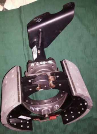
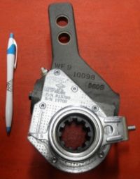
Those brake chambers are called a 30-30 can in the maintenance world. It's a spring brake and a service brake all in one. One hose is the air supply to release the emergency spring, the other hose is the service supply air. The service supply air is what actuated the brake chamber via the brake pedal. You'll have two air valves inside the cab. A red valve button and a yellow valve button. Yellow is to release the emergency spring in the brake chamber. It's what sets the brake when you park, OR sets the brakes in an emergency such as an air hose blowing cause you to lose air, in which case the emergency brakes will set automatically once it reaches 25psi.
The red air valve button supplies the trailer with air.
Armor/AFV
For discussions on tanks, artillery, jeeps, etc.
For discussions on tanks, artillery, jeeps, etc.
Hosted by Darren Baker, Mario Matijasic
My first HEMTT - the Italeri LHS
Thirian24

Joined: September 30, 2015
KitMaker: 2,493 posts
Armorama: 2,344 posts

Posted: Tuesday, September 06, 2016 - 10:50 PM UTC
Posted: Tuesday, September 06, 2016 - 11:59 PM UTC
Yep, was just out running some errands and got behind a Mack dump truck with the exact same Haldex brake actuators and twin air lines running to them!
Posted: Wednesday, September 07, 2016 - 12:15 AM UTC
If interested; there is an explanatory video on basic truck air brake and spring emergency brake operation on You Tube at:
https://www.youtube.com/watch?v=QVJSFlp8Pws
https://www.youtube.com/watch?v=QVJSFlp8Pws
Posted: Wednesday, September 07, 2016 - 04:23 AM UTC
Posted: Wednesday, September 07, 2016 - 06:23 AM UTC
Posted: Wednesday, September 07, 2016 - 07:58 AM UTC
Thirian24

Joined: September 30, 2015
KitMaker: 2,493 posts
Armorama: 2,344 posts

Posted: Wednesday, September 07, 2016 - 09:11 AM UTC
Looks great.
Posted: Wednesday, September 07, 2016 - 07:49 PM UTC
Thanks Dustin - glad you approve. Also thanks for that explanation on the double acting rear brakes.
You probably figured out that I have always been the kind of guy who wants to know "what's on the inside". Also I figure knowing how things are supposed to work can sometimes make for a better, more correct model.
You probably figured out that I have always been the kind of guy who wants to know "what's on the inside". Also I figure knowing how things are supposed to work can sometimes make for a better, more correct model.
Posted: Wednesday, September 07, 2016 - 08:53 PM UTC
Well I have a week's reprieve in that I just discovered that I had the dates for the Dayton IPMS competition wrong. It is the 17th of this month rather than this Saturday as I had thought. Perhaps I can get the gun ring done as well.
Posted: Wednesday, September 07, 2016 - 08:59 PM UTC
Dustin, the air for the rear brakes seems to go through some sort of distribution manifold/valve/controller. There is some confusion (on my part) reading the TM. Is there one distribution valve for each rear axle or is one valve for the service brakes and the other for the parking brakes?
These valves are mounted, one in front of and one just behind the rear H-frame member.
These valves are mounted, one in front of and one just behind the rear H-frame member.
Thirian24

Joined: September 30, 2015
KitMaker: 2,493 posts
Armorama: 2,344 posts

Posted: Wednesday, September 07, 2016 - 09:24 PM UTC
Can you post a picture of the TM?
Posted: Wednesday, September 07, 2016 - 11:02 PM UTC
Try'n to find it again!
Thirian24

Joined: September 30, 2015
KitMaker: 2,493 posts
Armorama: 2,344 posts

Posted: Thursday, September 08, 2016 - 12:05 AM UTC
Generally speaking, the air compressor will feed the air tanks, and then the air tanks will feed the distribution blocks and then they'll go to the brake chambers AND air bags if the application applies.
Posted: Thursday, September 08, 2016 - 01:37 AM UTC
Thirian24

Joined: September 30, 2015
KitMaker: 2,493 posts
Armorama: 2,344 posts

Posted: Thursday, September 08, 2016 - 01:52 AM UTC
Correct. One relay valve can supply multiple axles depending on how many ports it has. They also have a pressure relief clave built in.
Posted: Thursday, September 08, 2016 - 02:04 AM UTC
Thirian24

Joined: September 30, 2015
KitMaker: 2,493 posts
Armorama: 2,344 posts

Posted: Thursday, September 08, 2016 - 02:09 AM UTC
Great diagram there.
Epi

Joined: December 22, 2001
KitMaker: 3,586 posts
Armorama: 2,556 posts

Posted: Thursday, September 08, 2016 - 06:10 AM UTC
Mike, I was going to try a scratch those relay valves for my M983 but was scared away from it. Can't wait to see how you tackle them.
Posted: Thursday, September 08, 2016 - 11:47 AM UTC
Hi Mike
really coming along nicely, and thanks for sharing all the diagrams as its really helping me in quest to build multiple HEMMTs at the moment
Keith
really coming along nicely, and thanks for sharing all the diagrams as its really helping me in quest to build multiple HEMMTs at the moment
Keith
M4A1Sherman

Joined: May 02, 2013
KitMaker: 4,403 posts
Armorama: 4,078 posts

Posted: Thursday, September 08, 2016 - 04:10 PM UTC
Quoted Text
Hi Mike
really coming along nicely, and thanks for sharing all the diagrams as its really helping me in quest to build multiple HEMMTs at the moment
Keith
ALL of you guys are providing and sharing EXCELLENT info, drawings, etc! It's a welcome change from some of the other threads on this site, where people are bickering over some of the most INCONSEQUENTIAL CRAP, the "put-downs", and just out-and-out peevishness...
I've been following this thread right along from it's inception, and I've learned A LOT about the complexities and details of modern US Army vehicles!
THANKS to ALL!!!

Posted: Thursday, September 08, 2016 - 06:48 PM UTC
Thanks Dennis, WOW!
Posted: Thursday, September 08, 2016 - 09:41 PM UTC
Building the Relay Valves:
Start with some 3/32" tube and add four pieces of .035" rod.


Glue assemblies to some thin plastic sheet. (True up the vertical rods and allow to dry thoroughly.) Then I used some .080" octagonal rod to control the height of my sprue cutters in order to trim all the rods to the same .080" height.
Start with some 3/32" tube and add four pieces of .035" rod.


Glue assemblies to some thin plastic sheet. (True up the vertical rods and allow to dry thoroughly.) Then I used some .080" octagonal rod to control the height of my sprue cutters in order to trim all the rods to the same .080" height.
Taylornic

Joined: January 10, 2005
KitMaker: 337 posts
Armorama: 332 posts

Posted: Thursday, September 08, 2016 - 09:57 PM UTC
This will be THE go to thread for HEMTT builds! Nice work, Mike!
Posted: Friday, September 09, 2016 - 03:20 AM UTC
I do truly apologize for not announcing the following the minute I discovered it!
On the Italeri model (I can't speak for the Trumpeter kit.) the front four wheel drums are different than the rear four. Special care should be taken to insure that the correct drums are used in the correct locations. However there is nothing about the model that prevents you from putting the wheel drums on incorrectly! The most visible difference between the front and rear wheedl drums is that the wheel center housing projects out further on the rear wheel drums than it does on the front four drums.
As with most REAL wheel drums, the center of the drum is off-set relative to the centerline of the tire tread. With the HEMTT the off-set wheel drum can be mounted on the vehicle facing either way. Due to the presence of the steering mechanism on the first two axles the off-set of the wheel drum is to the outside to allow more space behind the wheel.
On the rear two axles the axles are actually narrower (no steering mechanism) so the off-set of the wheel drum faces the inside. Doing this keeps the finished tread width of all four axles approximately the same.
The same is true for almost any heavy truck.
As per the Italeri instruction sheet the front wheel drums are identified as parts 2G. The rear wheel drums are identified as parts 1G. Finally the wheel drum for the spare is identified as part 3G and has no wheel center at all.


. . . . . . . . . . . FRONT WHEEL DRUM . . . . . . . . . . . . . . . . . . . . . . . . . REAR WHEEL DRUM . . . . . . . . . .
. . . . . . . . . OUTWARD FACING OFF-SET . . . . . . . . . . . . . . . . . . . . . INWARD FACING OFF-SET . . . . . . . .
. . . . . . . . . . . LOW WHEEL CENTER . . . . . . . . . . . . . . . . . . . . . . . . . HIGH WHEEL CENTER . . . . . . . . .
On the Italeri model (I can't speak for the Trumpeter kit.) the front four wheel drums are different than the rear four. Special care should be taken to insure that the correct drums are used in the correct locations. However there is nothing about the model that prevents you from putting the wheel drums on incorrectly! The most visible difference between the front and rear wheedl drums is that the wheel center housing projects out further on the rear wheel drums than it does on the front four drums.
As with most REAL wheel drums, the center of the drum is off-set relative to the centerline of the tire tread. With the HEMTT the off-set wheel drum can be mounted on the vehicle facing either way. Due to the presence of the steering mechanism on the first two axles the off-set of the wheel drum is to the outside to allow more space behind the wheel.
On the rear two axles the axles are actually narrower (no steering mechanism) so the off-set of the wheel drum faces the inside. Doing this keeps the finished tread width of all four axles approximately the same.
The same is true for almost any heavy truck.
As per the Italeri instruction sheet the front wheel drums are identified as parts 2G. The rear wheel drums are identified as parts 1G. Finally the wheel drum for the spare is identified as part 3G and has no wheel center at all.


. . . . . . . . . . . FRONT WHEEL DRUM . . . . . . . . . . . . . . . . . . . . . . . . . REAR WHEEL DRUM . . . . . . . . . .
. . . . . . . . . OUTWARD FACING OFF-SET . . . . . . . . . . . . . . . . . . . . . INWARD FACING OFF-SET . . . . . . . .
. . . . . . . . . . . LOW WHEEL CENTER . . . . . . . . . . . . . . . . . . . . . . . . . HIGH WHEEL CENTER . . . . . . . . .
Posted: Friday, September 09, 2016 - 05:09 AM UTC
 |


