Finally I managed to complete the fuel tanks. These are the latest images of my works.
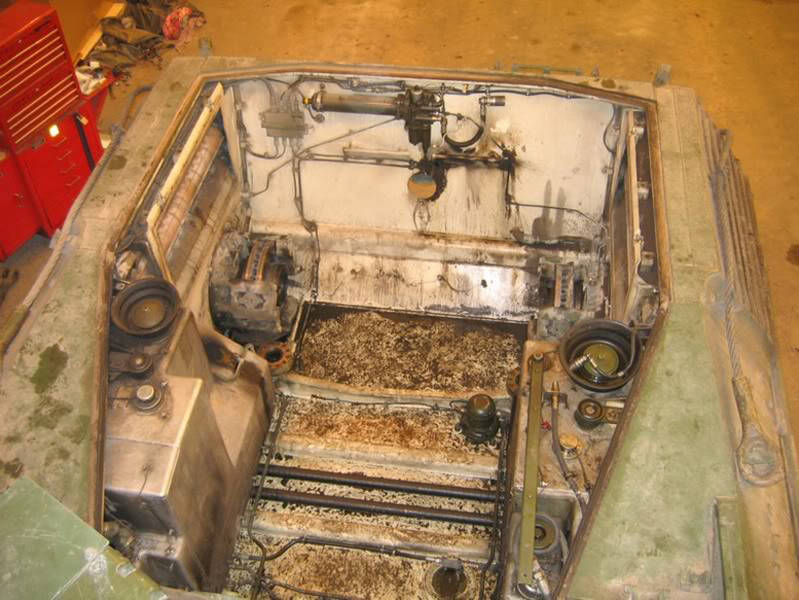
This is a picture that I found of the interior of the engine compartment.
From this photograph, and other images, I had to calculate the sizes and shapes of the various components and then reproduce them in the best way in scale.
This method of working is very long and imprecise, but it is the only method that I had on hand, although I have the "Operation and Maintenance Manual" and many publications on Leopard.
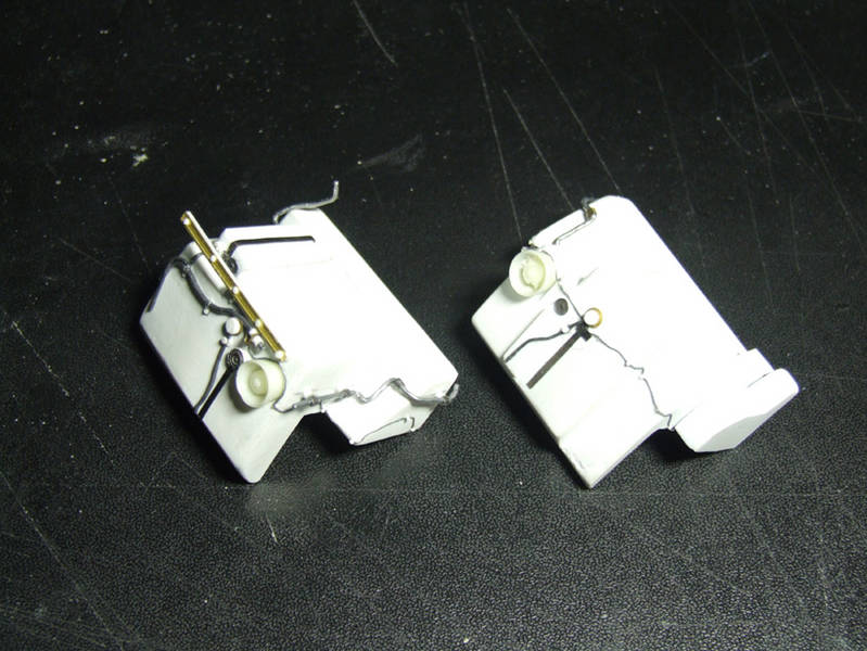
Side view of two fuel tanks in scratch.
To obtain them, I glued together some profiles of plasticard of various shapes and sizes, up to create the shape of the tank.
Later, with rasps and sandpaper, I brought the pieces to size and shape right.
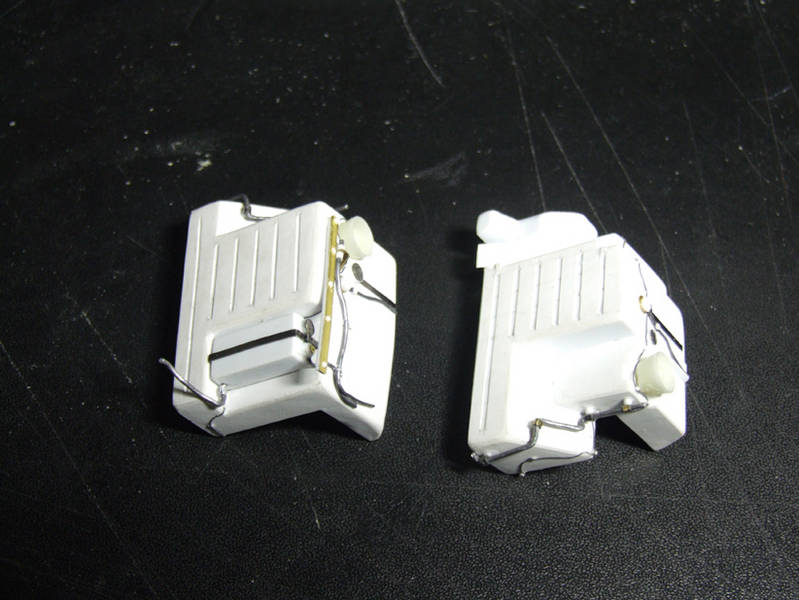
Another side view of two fuel tanks in scratch.
To cover the imperfections of the various sections of Evergreen and Plastruct used, I coated the surfaces with a unique part of a sheet of plasticard very thin (0.125 mm.) on which I cutted some slits to simulate the stiffening ribs in negative.
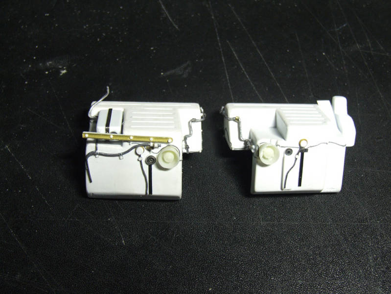
Top view of two fuel tanks self-built.
Finally, I completed the two tanks with all the details that I have identified on the photographs.
Most of them are in scratch, while some (like the rubber funnels of the filler caps) come from the set of the engine compartment of the Leopard, of "REAL MODELS" Factory ( No. RMA3504 of the catalog).
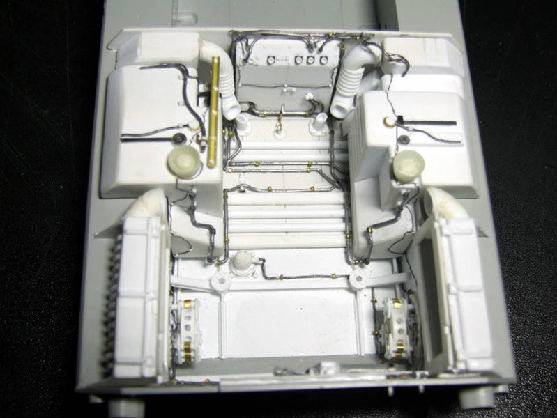
Top view of the engine compartment "almost" complete (without top armor).
The engine compartment is slowly completing with the details that compose it.
Finally I can see the end of the tunnel ... (maybe!).
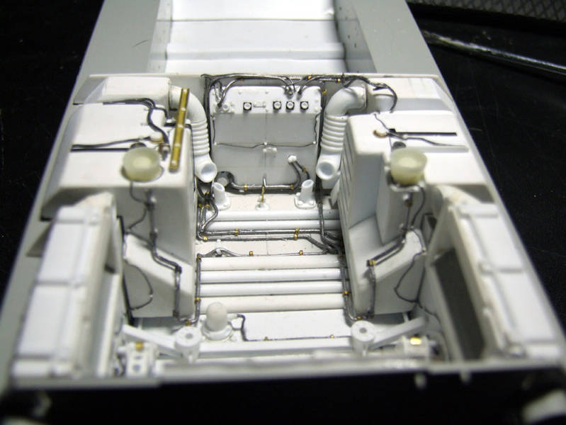
Another top view of the engine compartment, with no top armor.
The tubes that you see in the foreground, and which are fixed to the side walls of the fuel tanks are the lances who spray off the fireproof liquid, while the thin cable that surrounds the engine compartment is the sensor of fire protection system.
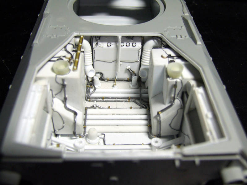
Top view of the engine compartment with top armor.
Test to check the dimensions of the various details with the top armor plate in place.
The feeling who I have now, is satisfaction for the work done so far.
Are there some imperfections and minor mistakes, but overall I managed to be quite accurate in the production of the various details.
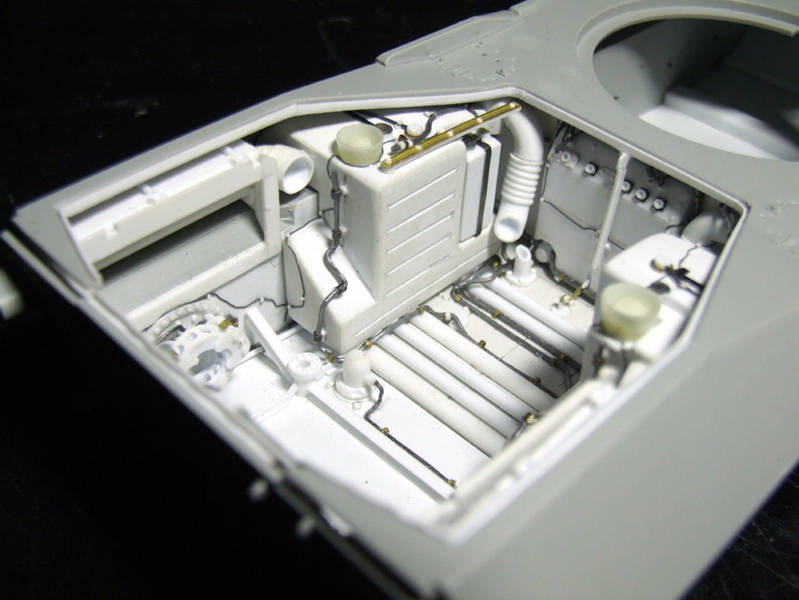
Left side view of the engine compartment with the top armor.
I have yet to coat the two compartments of the discharges with a piece of aluminum tape to simulate the thermal insulation material (very hard to clearly see if this thing is not known ... but well I know there is!) which prevents the overheat of the lower part of the hull of the tank produced by the exhaust gases.
This operation is still something that I will do at the last minute, because it is very easy and quick to do.
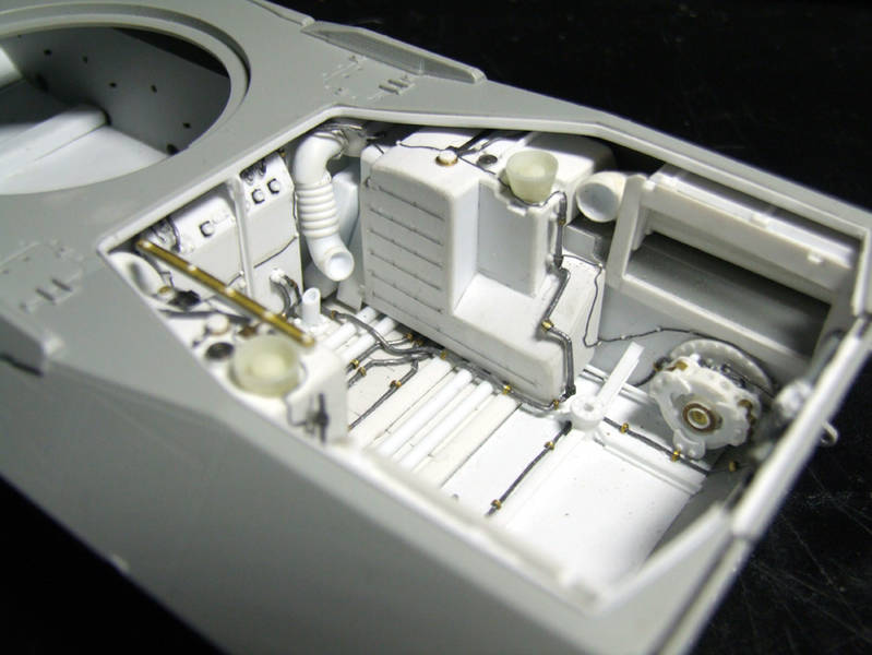
Right side view of the engine compartment with the top armor.
The bar bolted that is seen in the foreground is a tie rod which locks in place the support of the accelerator control of the regulator and the idling of the engine which, normally, are arranged on it.
When the engine is disassembled, first it is unhooked to remove even the command, and then is folded on the tank to which it is fixed.
The work on the engine compartment is almost finished.
There are only a few other small details for to complete the order.
Now I will concentrate to the realization of the interior of the hull (the pilot's seat) and the turret (the commander's seat), but only what is visible from the open hatches.
However, so far I am very pleased with the work I did.
At next time ...
Gianfranco "Il Colonnello"


