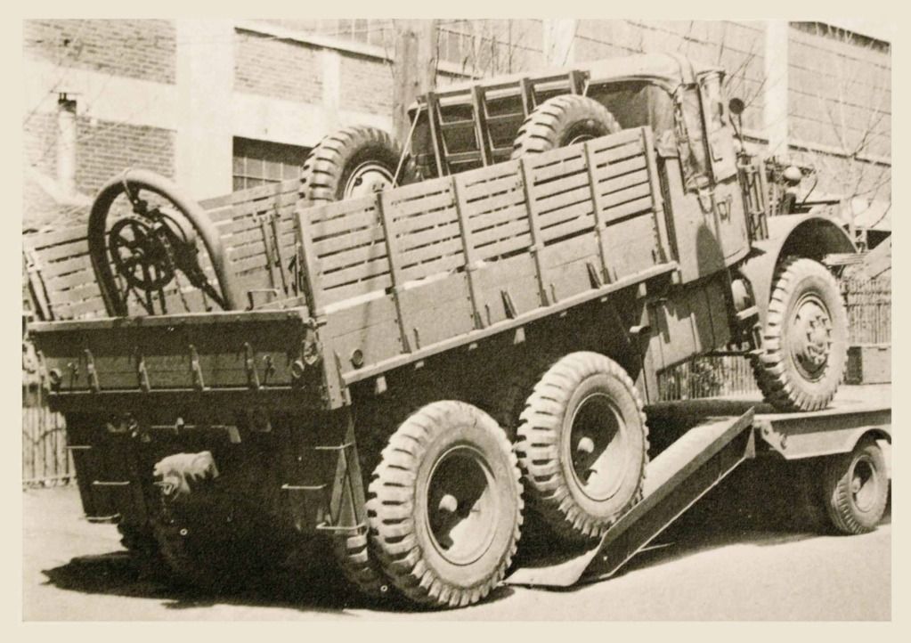
Mack NO6 - 7 1/2 ton artillery tractor

#521
Kentucky, United States
Joined: April 13, 2011
KitMaker: 9,465 posts
Armorama: 8,695 posts
Posted: Wednesday, May 08, 2013 - 04:35 AM UTC
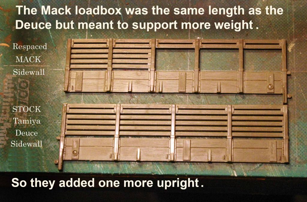
The wooden load box for the Mack was built by the same sub-contractor that built the early load boxes for the GMC Deuce and a Half. The load box fencing was the same length and height on both vehicles so it is no accident that the overall design and the metal hardware were similar on both. The only difference: The Mack had six vertical uprights instead of five as on the Deuce. I started with the load box sides off the Tamiya Deuce but I had to add one aditional upright and re-space the other five.
Here is a before and after example of the side walls for the model Mack:
I also joined and re-spaced the front fence of the load box and spliced two Tamiya Deuce tailgates together to round out my Mack. The load box floor and support structure was scratch built board on board, from distressed Evergreen shapes.(See photo posted earlier.)

#521
Kentucky, United States
Joined: April 13, 2011
KitMaker: 9,465 posts
Armorama: 8,695 posts
Posted: Wednesday, May 08, 2013 - 04:52 AM UTC
Load box photo from the Tech Manual:
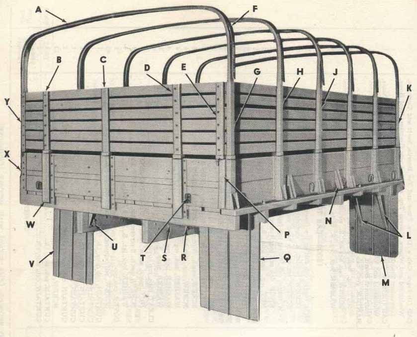 The above image comes from the collection of EASY 1 Productions - From the disc entitled "TM 10-1679; 7 1/2 ton 6x6 Prime Mover Mack NO"
Follow them on Facebook at:https://www.facebook.com/Easy1CD/
#521
Kentucky, United States
Joined: April 13, 2011
KitMaker: 9,465 posts
Armorama: 8,695 posts
Posted: Wednesday, May 08, 2013 - 11:53 AM UTC
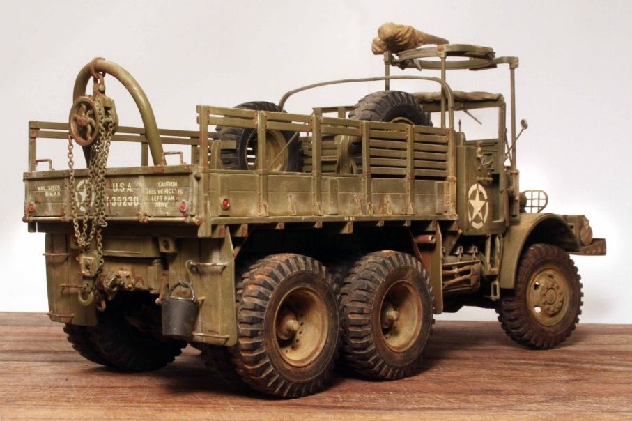
Rear view of the finished Mack model:

#521
Kentucky, United States
Joined: April 13, 2011
KitMaker: 9,465 posts
Armorama: 8,695 posts
Posted: Thursday, May 09, 2013 - 01:08 AM UTC
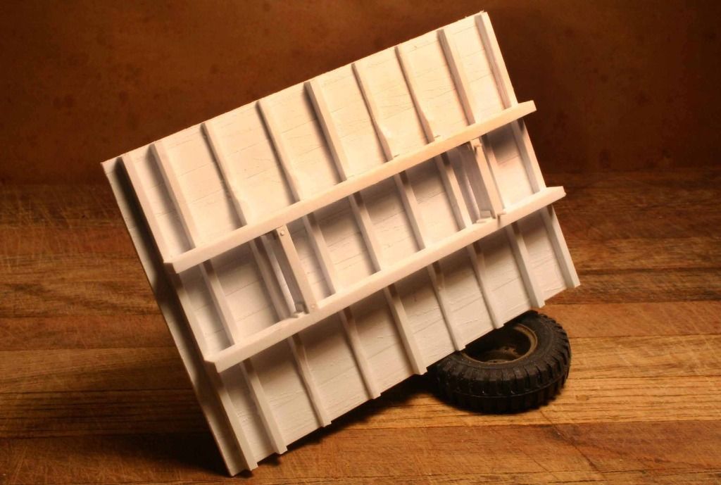
Again the wooden load box under construction as seen from below:
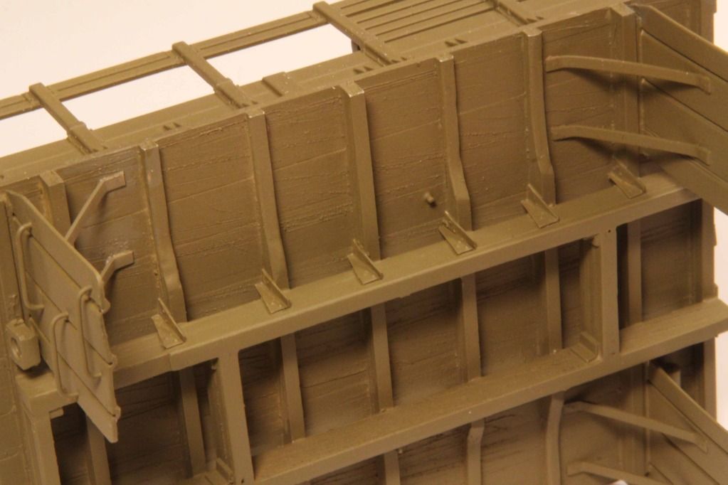
Individual board on board flooring construction:
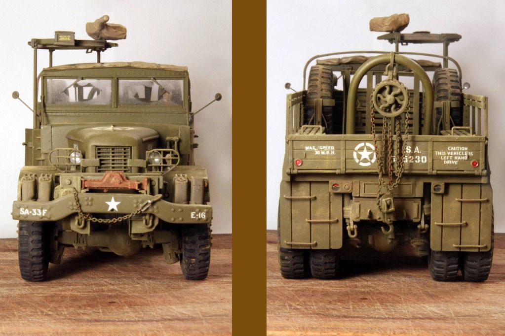
Com'n and Go'n
I used a saw blade scrapped along the length of the Evergreen plastic to create the wood grain in the load box floor. Then lightly sanded the now destressed "wood" to knock off the high spots and give the floor a well used look.

#521
Kentucky, United States
Joined: April 13, 2011
KitMaker: 9,465 posts
Armorama: 8,695 posts
Posted: Friday, May 10, 2013 - 07:45 AM UTC
THE FRONT AXLE with off-set differential and the modified Gar-Wood WINCH
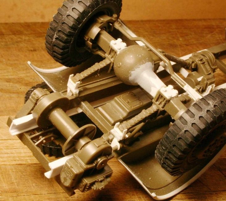
The Mack had a similar front differential to the Dragon Wagon however the Mack had a slightly wider stance and also the differential was off-set towards the driver's side for more underbody clearance. The Dragon Wagon had the differential centered on the front axle.
The inverted Gar-Wood winch on the front of the Mack is (more or less) the standard 20 ton unit as used on the Pacific Car & Foundry M26 Dragon Wagon. Changes made by the Gar-Wood Company to accomodate the NO6: The winch drum on the original Mack had to be narrowed on its' shaft to clear the two frame members coming through the winch assembly . Also the drag brake on the winch was not the band style as on the M26 but an earlier brake block design.
PLEASE NOTE: The axle retainer bolts added to the Mack. For some reason this is a significant detail that was also left off the front axle of the Tamiya Dragon Wagon. Easily added with some Evergreen octagonal stock.
ALSO OF NOTE: At this point early in the construction process the frame is still just a straight channel structure, front to rear. (as on the Dragon Wagon.) I had not yet discovered that the Mack employed an offset frame that made a vertical jog up and over the front axle allowing the vehicle to sit lower. (More on this later.)

#521
Kentucky, United States
Joined: April 13, 2011
KitMaker: 9,465 posts
Armorama: 8,695 posts
Posted: Friday, May 10, 2013 - 07:56 AM UTC
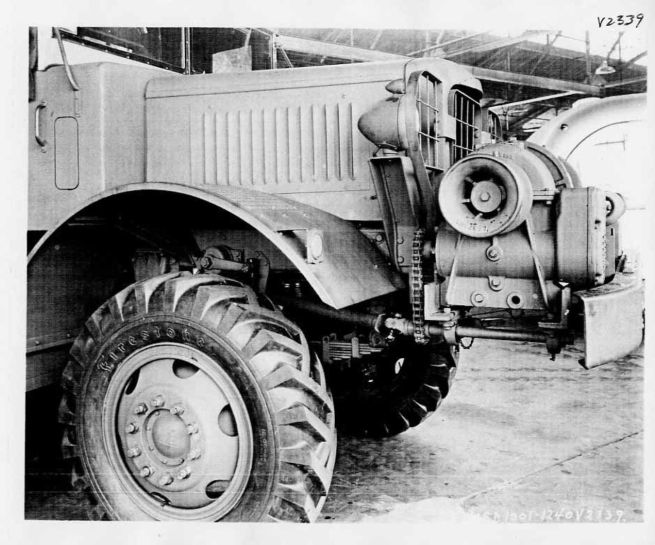
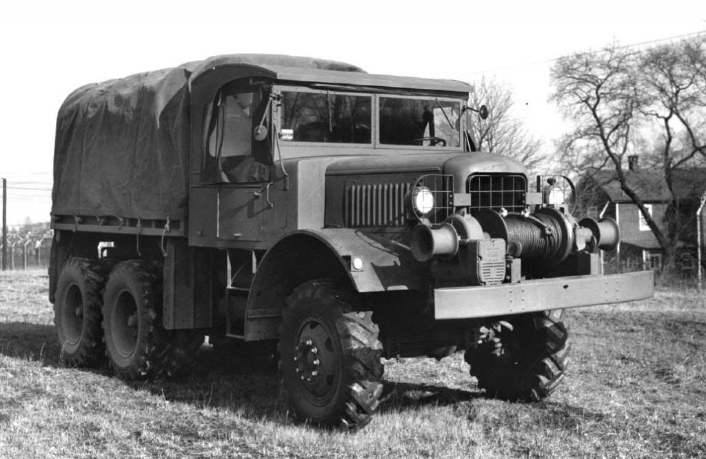
Undo the 8 to 10 large mounting bolts and the entire winch, bumper and ladder rack assembly would slide off the end of the frame.
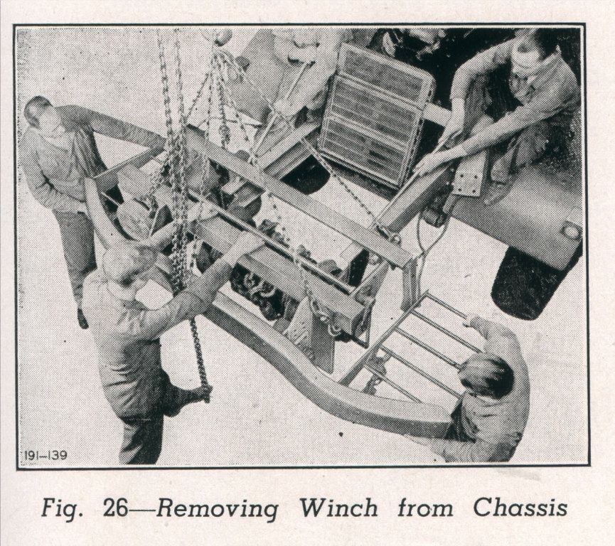
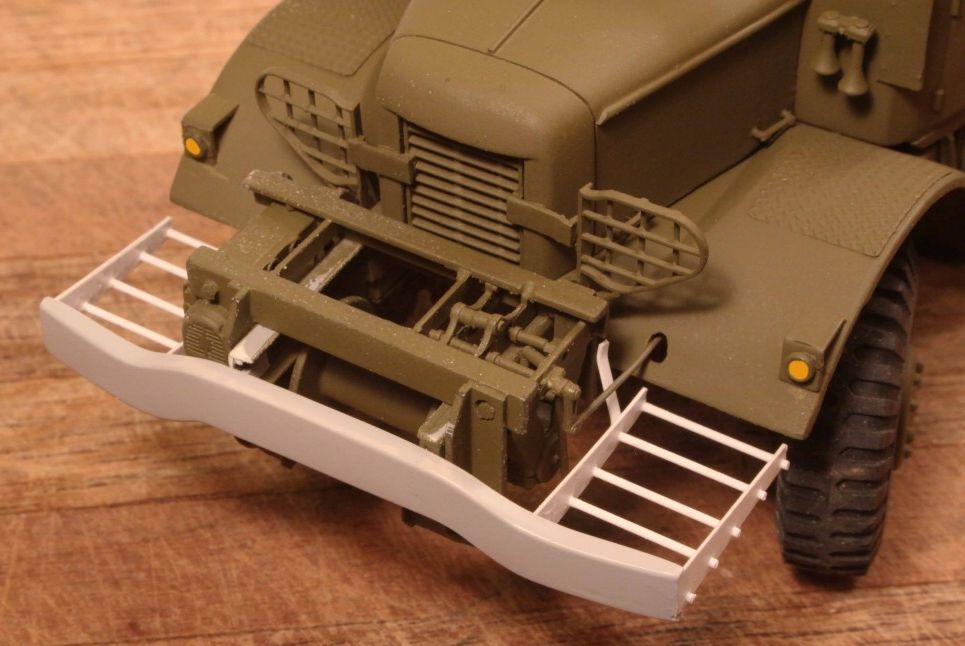 The upper image comes from the collection of EASY 1 Productions - From the disc entitled "TM 10-1679; 7 1/2 ton 6x6 Prime Mover Mack NO"
Follow them on Facebook at:https://www.facebook.com/Easy1CD/
#521
Kentucky, United States
Joined: April 13, 2011
KitMaker: 9,465 posts
Armorama: 8,695 posts
Posted: Friday, May 10, 2013 - 08:03 AM UTC
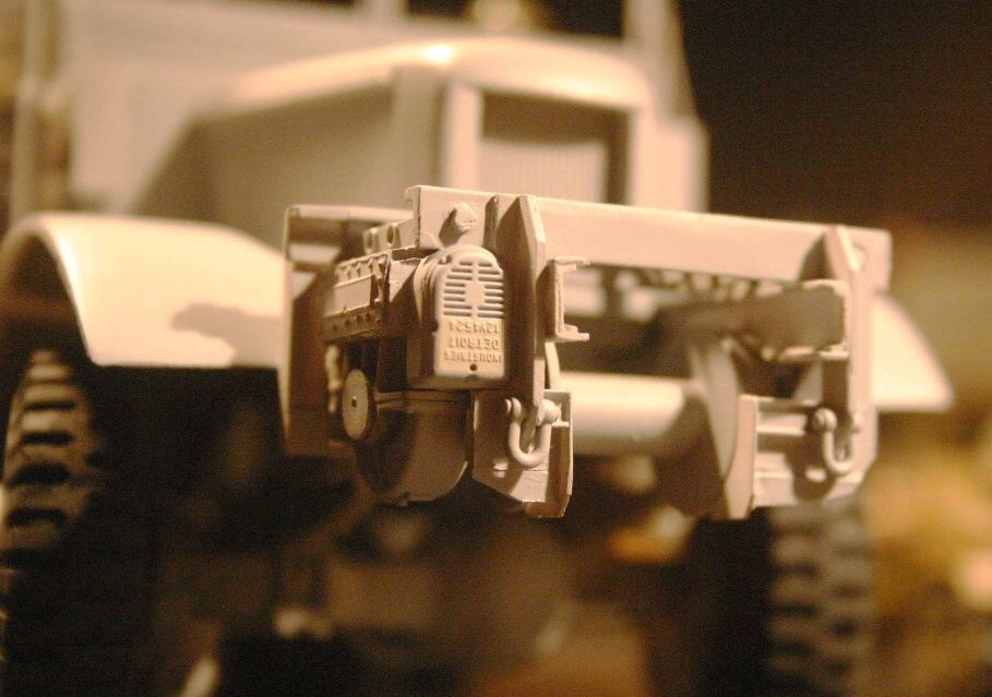
The redesigned earlier style drag brake has yet to be built for the Mack winch.

#521
Kentucky, United States
Joined: April 13, 2011
KitMaker: 9,465 posts
Armorama: 8,695 posts
Posted: Friday, May 10, 2013 - 08:34 AM UTC
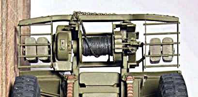
Underside view of the finished 20 ton Gar-Wood winch with the earlier style drag brake installed on the right side of the winch drum in this photo:

#521
Kentucky, United States
Joined: April 13, 2011
KitMaker: 9,465 posts
Armorama: 8,695 posts
Posted: Friday, May 10, 2013 - 08:43 AM UTC
Original prototype winch design for Mack NO used the totally stock 20 ton Gar-Wood winch mounted directly on top of the frame members. Unfortunately as the winch approached anywhere near its maximun pull the twisting force placed on the assembly would perminently distort the frame members and destroy the vehicle. The inverted design allowed the axis of the winch drum to be much lower and more in line with the frame members avoiding this problem.

#521
Kentucky, United States
Joined: April 13, 2011
KitMaker: 9,465 posts
Armorama: 8,695 posts
Posted: Monday, May 13, 2013 - 01:50 AM UTC
BUILDING THE LADDER RACKS
(This process will work for building any custom ladder structure.)
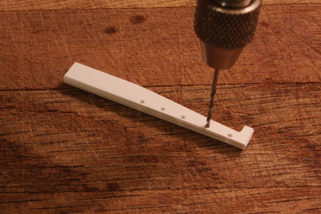
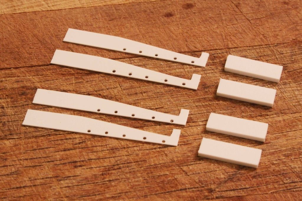
In this case I needed a total of four matching side plates to make the two racks. I cut four exactly equal lengths of Evergreen plastic stock but intentionally cut them longer than needed.
I then glued the four pieces together at each end using only the last 1/8 inch of the overly long stock for the glue. After the glue has completely dried, sand the stock to the desired profile if necessary and drill all four pieces at the same time to provide matching, equally spaced mounting holes for the ladder rungs.

#521
Kentucky, United States
Joined: April 13, 2011
KitMaker: 9,465 posts
Armorama: 8,695 posts
Posted: Monday, May 13, 2013 - 02:00 AM UTC
After drilling and shaping, carefully seperate the four drilled pieces. Now manufacture four EXACTLY EQUAL spacers that will give you the desired ladder width required. Care should be taken at this step otherwise you ladders will not be "square" when complete.
Istanbul, Turkey / Türkçe
Joined: February 12, 2013
KitMaker: 64 posts
Armorama: 62 posts
Posted: Monday, May 13, 2013 - 02:01 AM UTC
Awesome built. Thank you for sharing.


#521
Kentucky, United States
Joined: April 13, 2011
KitMaker: 9,465 posts
Armorama: 8,695 posts
Posted: Monday, May 13, 2013 - 02:09 AM UTC
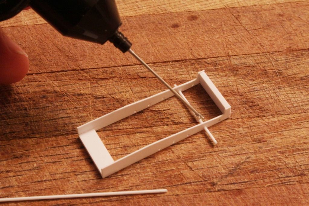
Assemble the side plates and the temporary spacers with glue. I carely layed the assembly on the work bench and blocked it into a carpenter's square as it was drying to insure the finished rack would be square.
Once the spacer assembly is completely dry insert plastic rod into the drill holes and add a small drop of glue to each end of the ladder rung. Again allow to dry thoroughly.

#521
Kentucky, United States
Joined: April 13, 2011
KitMaker: 9,465 posts
Armorama: 8,695 posts
Posted: Monday, May 13, 2013 - 02:18 AM UTC
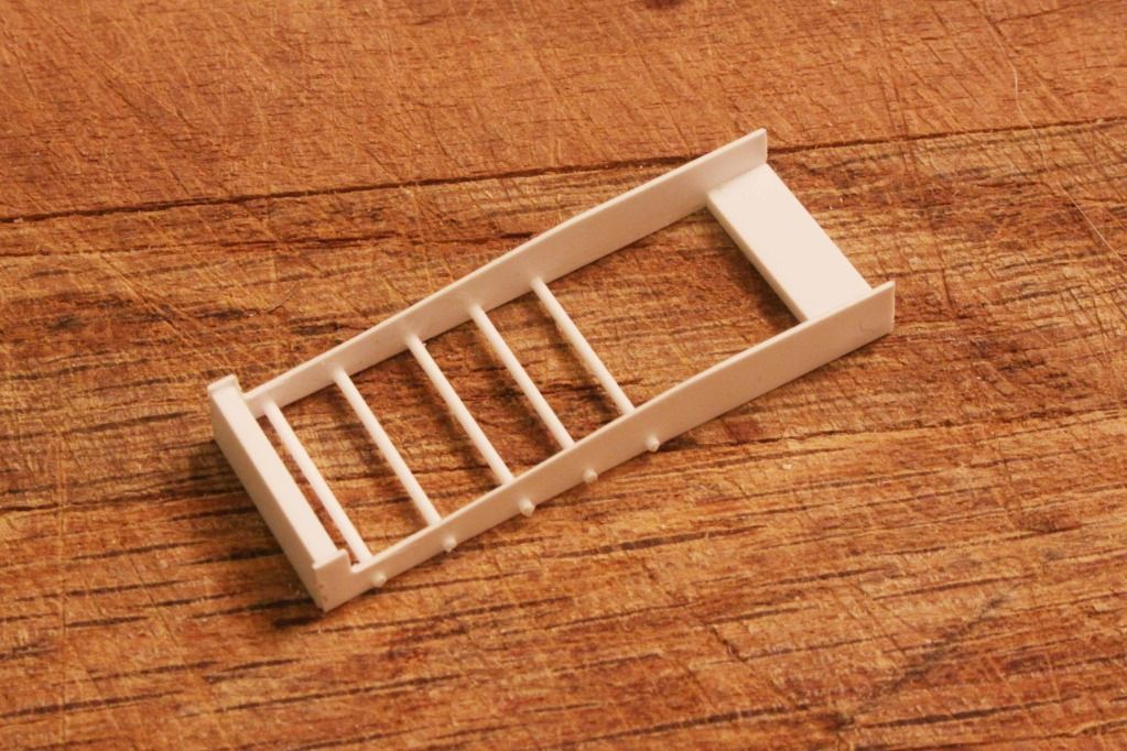
Once dry (overnight) cut the excess rod of the ladder rungs to the correct length (either flush or with a slight "bolt head" showing)
Now in the next step you can carefully cut the side plates to their finished length which will also serve to remove the temporary spacer bars.

#521
Kentucky, United States
Joined: April 13, 2011
KitMaker: 9,465 posts
Armorama: 8,695 posts
Posted: Monday, May 13, 2013 - 02:23 AM UTC
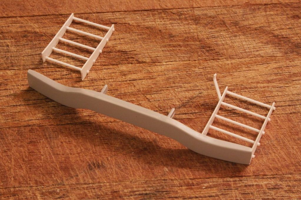
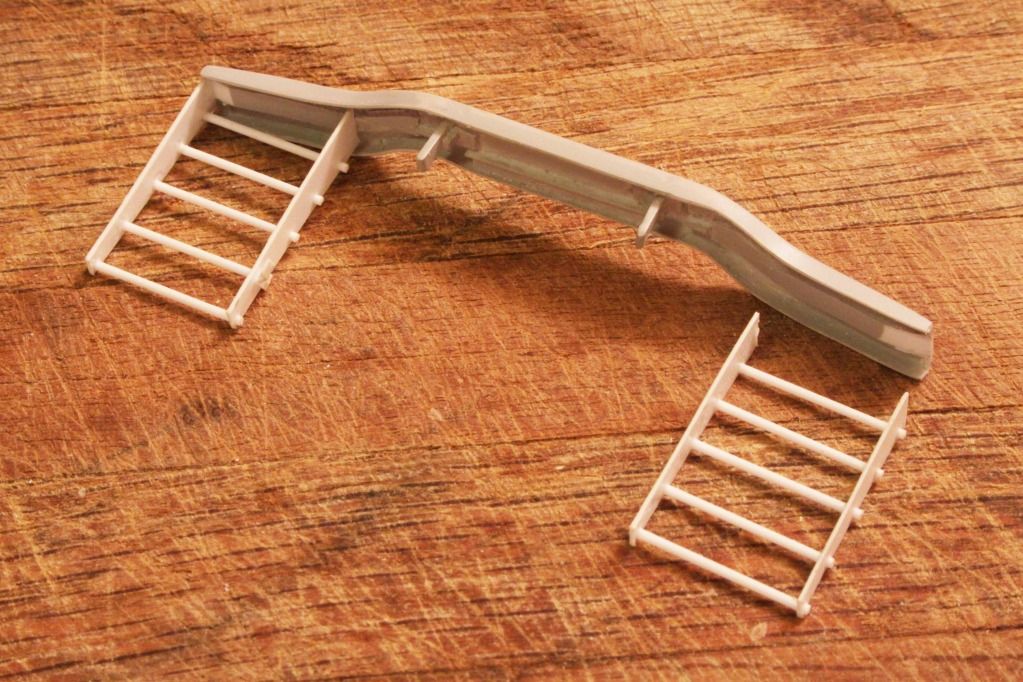
The finished racks, cut to lengh and ready to be attached to the bumper:

#521
Kentucky, United States
Joined: April 13, 2011
KitMaker: 9,465 posts
Armorama: 8,695 posts
Posted: Monday, May 13, 2013 - 02:37 AM UTC
The finished and installed ladder racks:
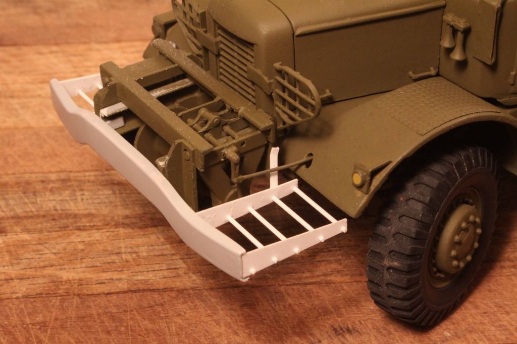
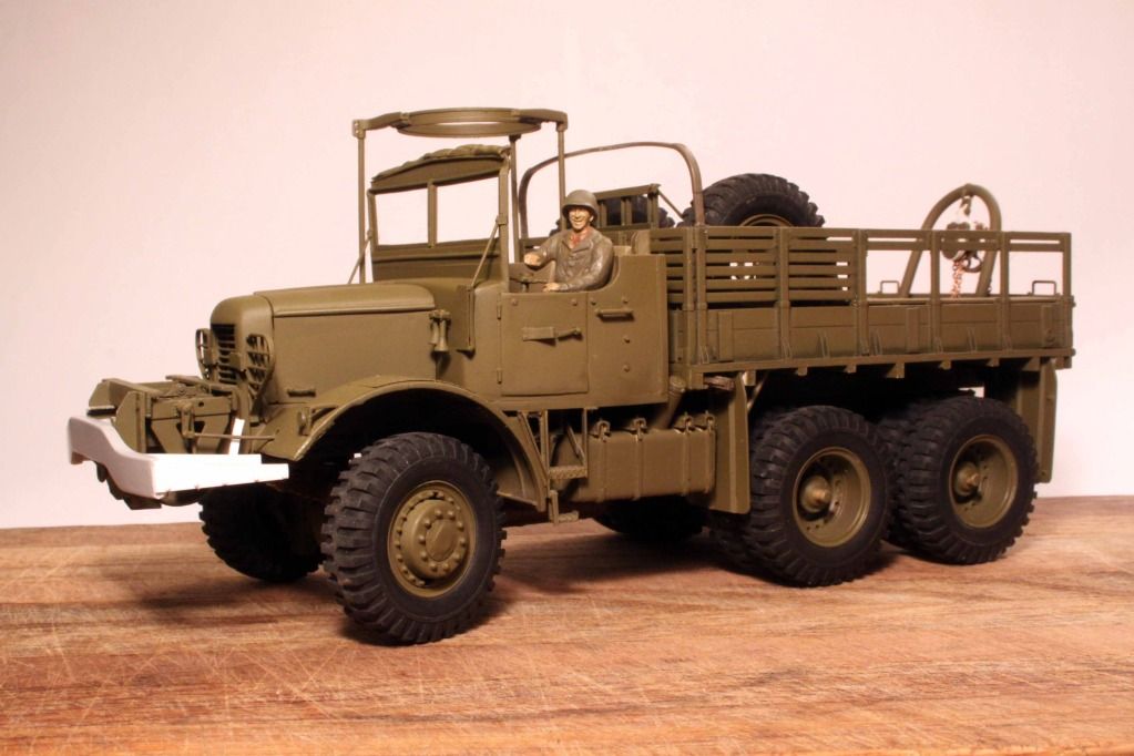
ANOTHER POINT OF NOTE: In the photos shown here it is still early in the overall construction process. The model here is still wearing the more or less stock Dragon Wagon front wheels which are incorrect for the Mack.
(More on this later.)

#521
Kentucky, United States
Joined: April 13, 2011
KitMaker: 9,465 posts
Armorama: 8,695 posts
Posted: Monday, May 13, 2013 - 02:43 AM UTC
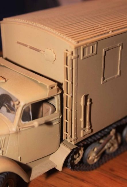
As I say, this construction process can be used to make almost any custon ladder structure.
Such as this unusually narrow ladder on a German Blitz "Mule".

#521
Kentucky, United States
Joined: April 13, 2011
KitMaker: 9,465 posts
Armorama: 8,695 posts
Posted: Monday, May 13, 2013 - 02:45 AM UTC
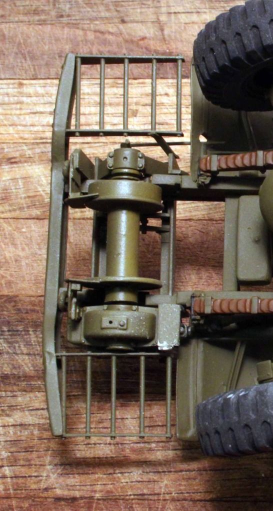
Completed, installed and painted ladder racks only waiting for the gas cans to be added.

#521
Kentucky, United States
Joined: April 13, 2011
KitMaker: 9,465 posts
Armorama: 8,695 posts
Posted: Monday, May 13, 2013 - 03:17 AM UTC
Quoted Text
Please Note: The axle retainer bolts added to the Mack. For some reason this is a significant detail that was also left off the front axle of the Tamiya Dragon Wagon. Easily added with some Evergreen octagonal stock.
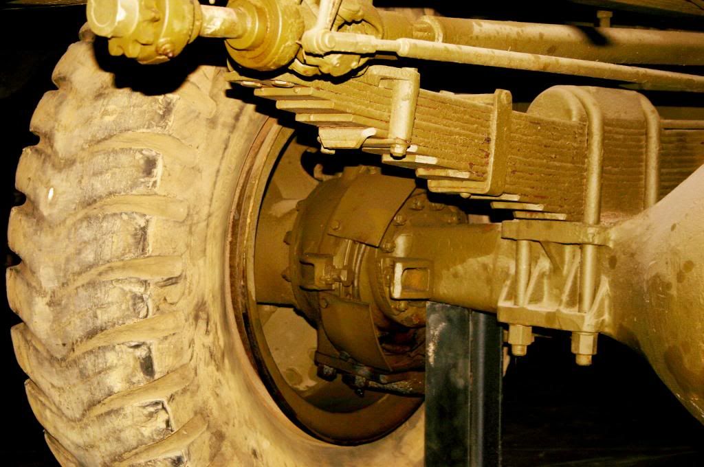
Photo of the front axle of the Dragon Wagon showing the prominent axle mounting bolts NOT present on the Tamiya model of the M26 Dragon Wagon. - My personal photo taken at the Auburn Victory Museum

#521
Kentucky, United States
Joined: April 13, 2011
KitMaker: 9,465 posts
Armorama: 8,695 posts
Posted: Monday, May 13, 2013 - 05:05 AM UTC
A beautifully restored Mack NO6 now living in the UK. This Mack has a steel load box. Surviving Macks that were transfered into the hands of various US Allies post-war were almost all converted to steel load boxes in the fifties and sixties. (Note the correct front wheel hubs shown here.)
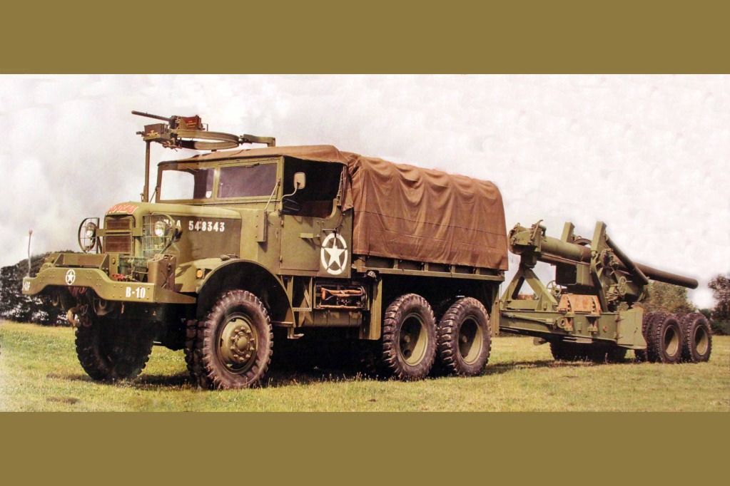
Photo comes from the pages of "Classic Military Vehicle" Magazine; published in the UK, a publication I highly recommend! AND it is now available online in an electronic form at:
http://www.cmvmag.co.uk/

#521
Kentucky, United States
Joined: April 13, 2011
KitMaker: 9,465 posts
Armorama: 8,695 posts
Posted: Monday, May 13, 2013 - 05:17 AM UTC
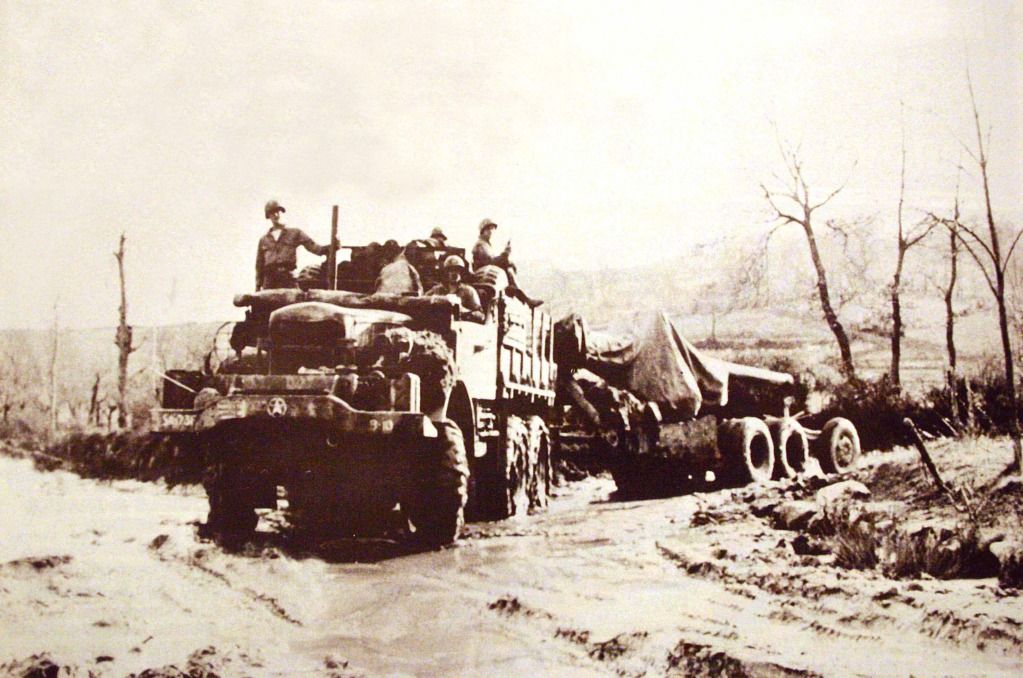
A wartime photo of the NO6 towing the 155mm US gun and behind that, the M1 Limber. The gun must have originally been emplaced by the M4 High Speed Tractor that requires the Limber. In this photo the gun is being relocated by the Mack but the Limber is tagging along behind.

#521
Kentucky, United States
Joined: April 13, 2011
KitMaker: 9,465 posts
Armorama: 8,695 posts
Posted: Monday, May 13, 2013 - 08:50 AM UTC
The special Mack designed towing hitch transfered part of the weight of the gun forward to the towing vehicle. So the Mack, unlike say the Diamond T ballast tractor, did not require the addition of dead weight ballast to gennerate the necessary tractive effort to tow the gun. This design conserved fuel and required two fewer tires on the pavement in order to move the load therefore saving on physical drag as well as precious wartime rubber.

#521
Kentucky, United States
Joined: April 13, 2011
KitMaker: 9,465 posts
Armorama: 8,695 posts
Posted: Monday, May 13, 2013 - 10:54 PM UTC
I wish I had had these drawings BEFORE building the first frame for my Mack. It would have saved me a lot of unnecessary rework!
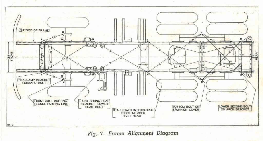
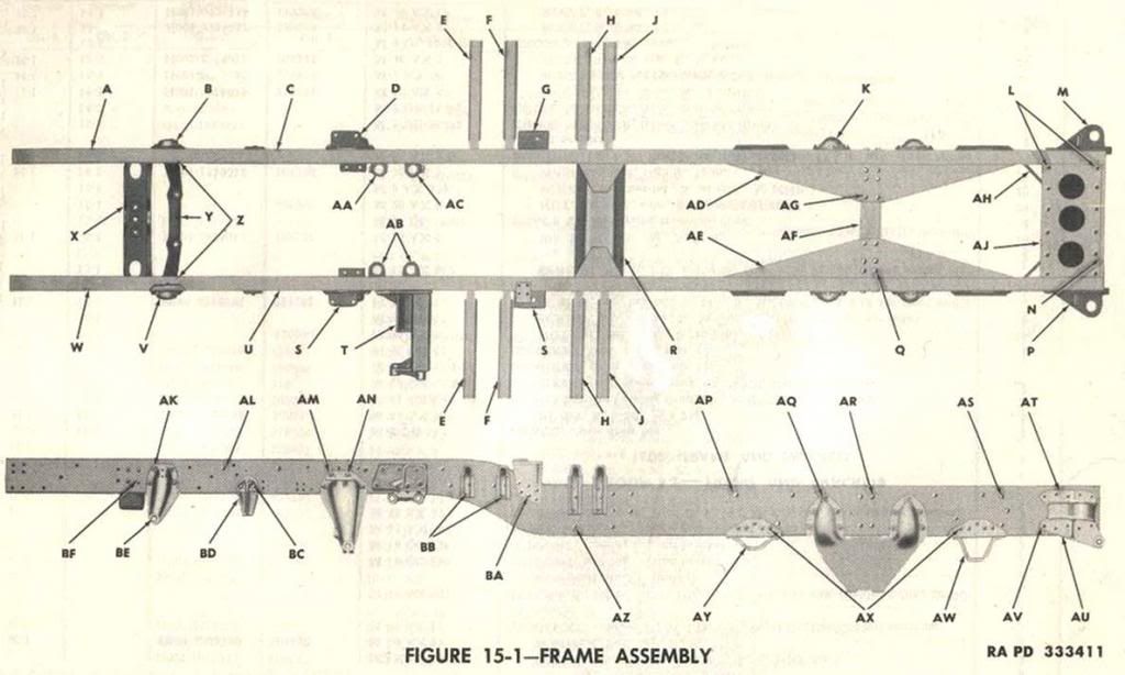 The above images come from the collection of EASY 1 Productions - From the disc entitled "TM 10-1679; 7 1/2 ton 6x6 Prime Mover Mack NO"
Follow them on Facebook at:https://www.facebook.com/Easy1CD/
#521
Kentucky, United States
Joined: April 13, 2011
KitMaker: 9,465 posts
Armorama: 8,695 posts
Posted: Tuesday, May 14, 2013 - 03:02 AM UTC
This illustration shows the mounting means for the cab floor sub frame. Note the spring loaded bolts to give the cab some flexibility of movement.
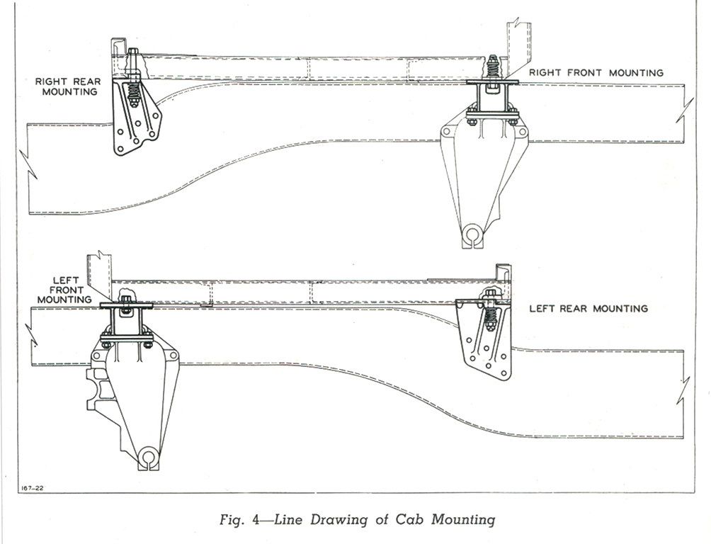 The above image comes from the collection of EASY 1 Productions - From the disc entitled "TM 10-1679; 7 1/2 ton 6x6 Prime Mover Mack NO"
Follow them on Facebook at:https://www.facebook.com/Easy1CD/
#521
Kentucky, United States
Joined: April 13, 2011
KitMaker: 9,465 posts
Armorama: 8,695 posts
Posted: Wednesday, May 15, 2013 - 04:38 AM UTC
[quote]
Quoted Text
The axle retainer bolts: For some reason this significant detail has been left off the front axle of the Tamiya Dragon Wagon.
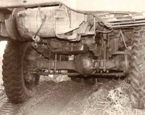
Here is a better view of the Gar-Wood drag brake mechanism in the above photo.
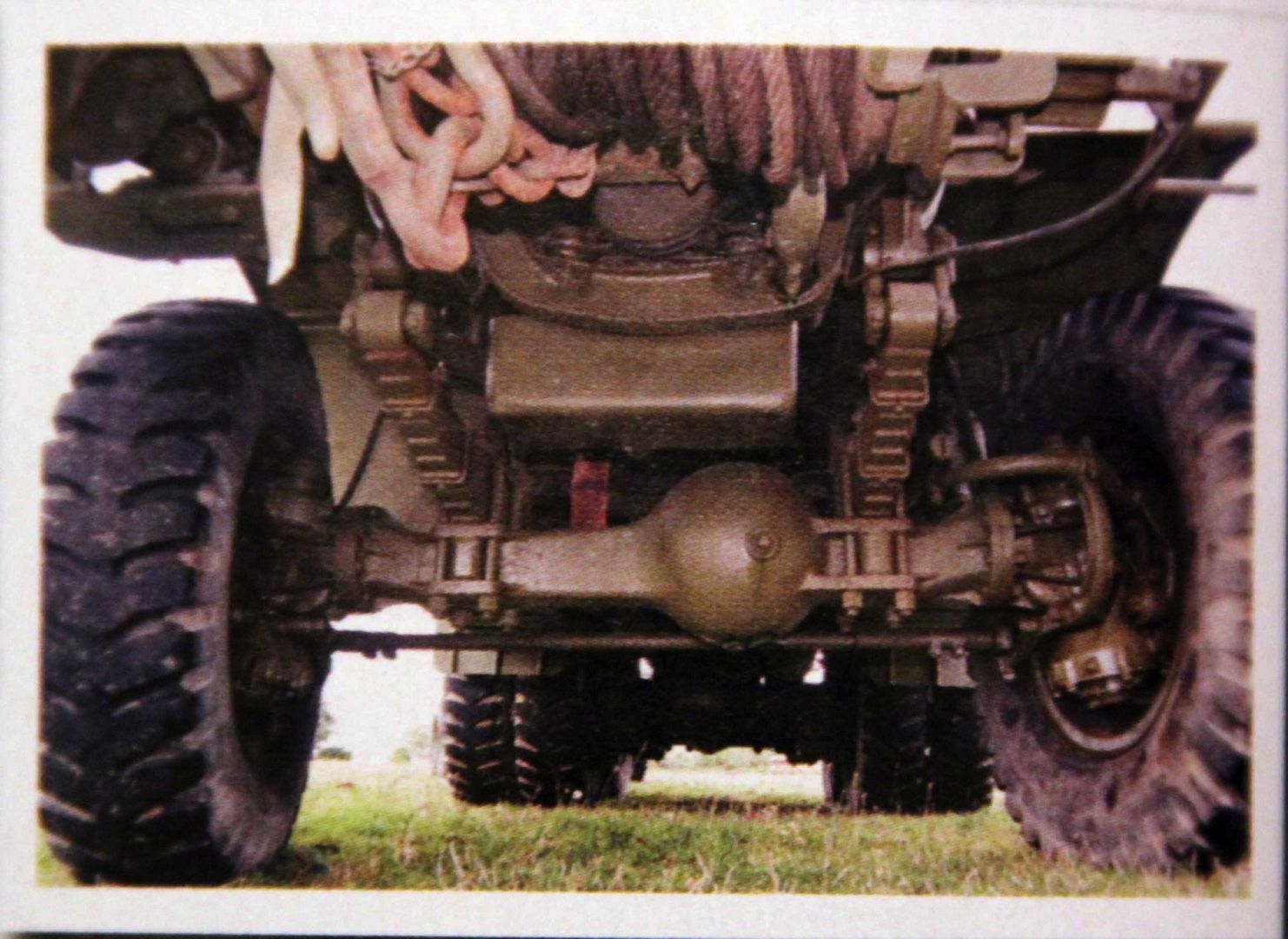
Also Note: The oversized engine oil pan extending downward just behind the frame cross member.


