MAZ 537 F/A Pusher Tractor

#521
Kentucky, United States
Joined: April 13, 2011
KitMaker: 9,465 posts
Armorama: 8,695 posts
Posted: Sunday, March 09, 2014 - 03:41 AM UTC

#521
Kentucky, United States
Joined: April 13, 2011
KitMaker: 9,465 posts
Armorama: 8,695 posts
Posted: Friday, April 25, 2014 - 07:28 AM UTC
Sorry folks, I was foolishly editing my Photobucket albums and inadvertently corrupted most all the links to this blog thread, darn it,
I have now started basic construction on this vehicle so it is a rotten time to mess up the links. I hope this will turn into a worthwhile build log so my apologies!


#521
Kentucky, United States
Joined: April 13, 2011
KitMaker: 9,465 posts
Armorama: 8,695 posts
Posted: Friday, April 25, 2014 - 07:46 AM UTC
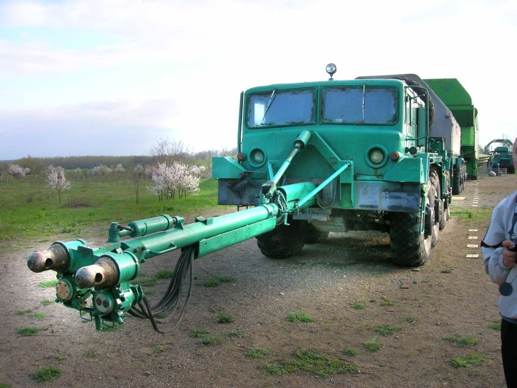
The F/A pusher tractor was used in conjunction with a forward E series 537 tractor for bringing the really large Russian ICBM's from the assembly plant to the missile silo base.
The missiles where so heavy and large that the trailer itself was remotely powered using electric motors. These motors ran off generators geared directly to the engines on the fore and aft 537's.


#521
Kentucky, United States
Joined: April 13, 2011
KitMaker: 9,465 posts
Armorama: 8,695 posts
Posted: Friday, April 25, 2014 - 07:55 AM UTC

#521
Kentucky, United States
Joined: April 13, 2011
KitMaker: 9,465 posts
Armorama: 8,695 posts
Posted: Friday, April 25, 2014 - 07:57 AM UTC

__________________________________________________
A MAZ-534D with a somewhat smaller missile trailer - no active electric drive requied:


#521
Kentucky, United States
Joined: April 13, 2011
KitMaker: 9,465 posts
Armorama: 8,695 posts
Posted: Friday, April 25, 2014 - 08:05 AM UTC
I am guessing the rear load body is an enlarged ballast body with lead weights much like the aircraft tug varriant of the 537.
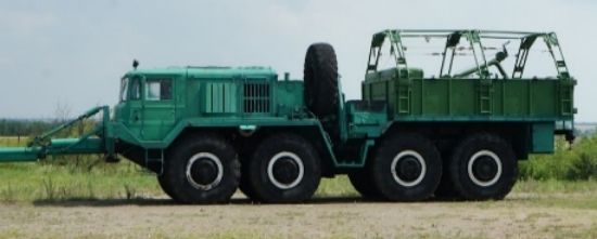
Note the stowed jib crane for loading/unloading from the ballast body.

#521
Kentucky, United States
Joined: April 13, 2011
KitMaker: 9,465 posts
Armorama: 8,695 posts
Posted: Friday, April 25, 2014 - 08:34 AM UTC

#521
Kentucky, United States
Joined: April 13, 2011
KitMaker: 9,465 posts
Armorama: 8,695 posts
Posted: Friday, April 25, 2014 - 08:50 AM UTC
A preserved example of this very rare vehicle on display at the Strategic Missile Forces Museum;
Ukraine, Kirovohrad region, Golovanovsky District, pgt. Pobuzhskoe.
Phone: +38 (05161) 7-39-72 or 6-54-27,
Fax: 7-32-30
The Museum website can be viewed at:
http://englishrussia.com/2011/04/18/strategic-missile-forces-museum/
#521
Kentucky, United States
Joined: April 13, 2011
KitMaker: 9,465 posts
Armorama: 8,695 posts
Posted: Friday, April 25, 2014 - 08:58 AM UTC
Here is an edited (corrections made by your's truely) drawing set of both the 537E puller tractor & 537F/A pusher tractor. (Image found on the internet.)
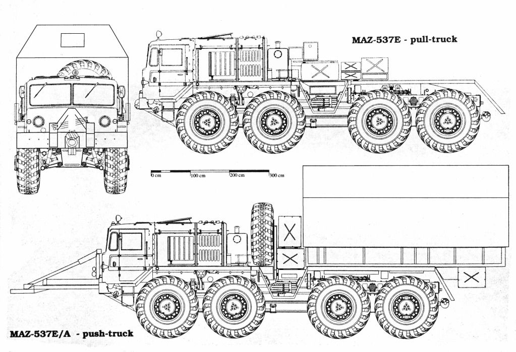
As found, the drawing had the spare tire centered on the vehicle and the gas tanks were totally missing on the Pusher Tractor.
In these drawings there are still problems with the position and length of the rear loadbox as well as the rear fenders. Further research will hopefully clear up these questions.

#521
Kentucky, United States
Joined: April 13, 2011
KitMaker: 9,465 posts
Armorama: 8,695 posts
Posted: Friday, April 25, 2014 - 12:46 PM UTC
Off topic but of some possible interest:
Trailer erector fixture for loading missile into launch silo.


#521
Kentucky, United States
Joined: April 13, 2011
KitMaker: 9,465 posts
Armorama: 8,695 posts
Posted: Friday, April 25, 2014 - 12:48 PM UTC

#521
Kentucky, United States
Joined: April 13, 2011
KitMaker: 9,465 posts
Armorama: 8,695 posts
Posted: Saturday, April 26, 2014 - 02:54 AM UTC
The generator pack behind the gas tanks on both the 537 E series as well as the F/A.
On the E tractor the electric supply wiring feeds to the rear of the vehicle. On the F/A there are enclosed wireways along the running boards allowing the electricial supply feed to go around the cabin all the way to the front of the vehicle.
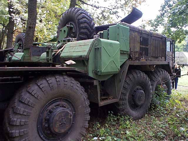
As you can see here you are free to model the E tractor using either the early or late production MAZ kits. Actually using the early production MAZ for the E would probably be more correct! As the missiles got heavier the F/A tractors were added later as pushers so chances are all F/A's were built using the later production tractor.

#521
Kentucky, United States
Joined: April 13, 2011
KitMaker: 9,465 posts
Armorama: 8,695 posts
Posted: Saturday, April 26, 2014 - 02:55 AM UTC

#521
Kentucky, United States
Joined: April 13, 2011
KitMaker: 9,465 posts
Armorama: 8,695 posts
Posted: Saturday, April 26, 2014 - 03:10 AM UTC
Early production E model 537 tractor.
Shown here is one of the forward "pull" tractors so the electrical cables are routed to the rear to attach to the active drive trailer. The electrical arrangement of the F/A "push" tractor would be considerably different as power must be routed forward, around the cab to the push probe on the front bumper, from there to be connected to the powered trailer.
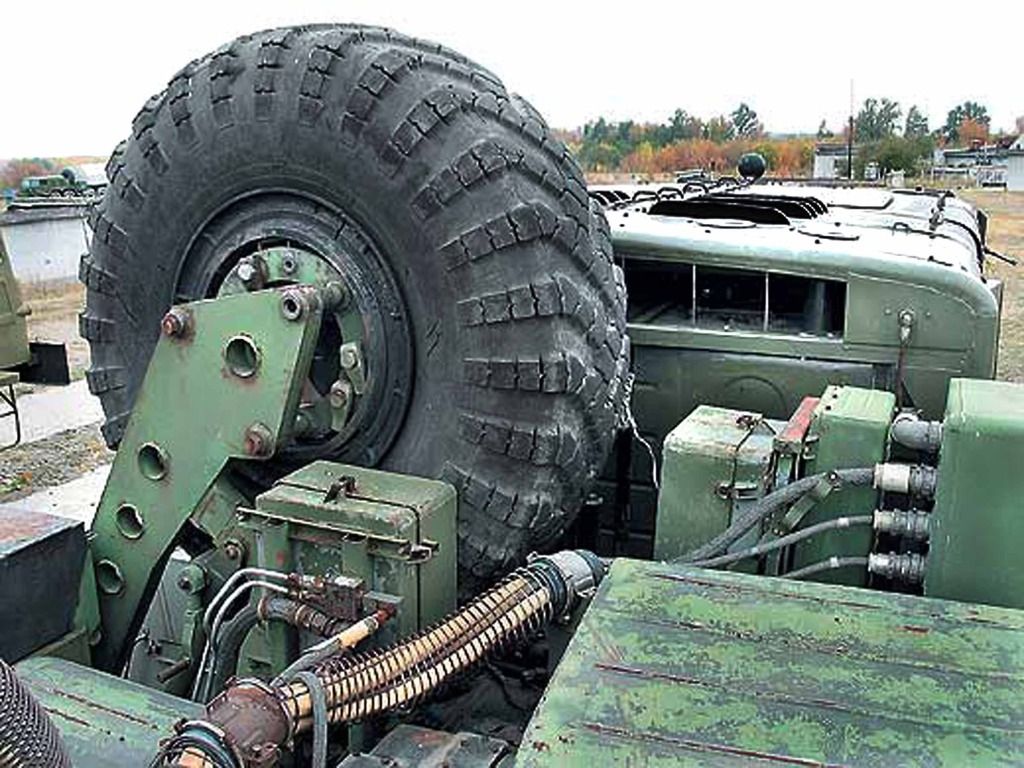
Love that big honking spare tire!

#521
Kentucky, United States
Joined: April 13, 2011
KitMaker: 9,465 posts
Armorama: 8,695 posts
Posted: Saturday, April 26, 2014 - 03:19 AM UTC
I feel the gen-pack must be run off the PTO on top of the transfer case. However research continues. If anyone has any reference here PLEASE chime in!

#521
Kentucky, United States
Joined: April 13, 2011
KitMaker: 9,465 posts
Armorama: 8,695 posts
Posted: Saturday, April 26, 2014 - 05:24 AM UTC
I often wonder why only a select few 537 trucks carry spare ties??

#521
Kentucky, United States
Joined: April 13, 2011
KitMaker: 9,465 posts
Armorama: 8,695 posts
Posted: Saturday, April 26, 2014 - 06:23 AM UTC
The MAZ TM manual that is available online seems to cover only up to the Series D vehicle which has simply a basic electric generator in a big rectangular box, for general use purposes and this generator DOES appear to be driven off the PTO.

#521
Kentucky, United States
Joined: April 13, 2011
KitMaker: 9,465 posts
Armorama: 8,695 posts
Posted: Saturday, April 26, 2014 - 07:54 AM UTC
The photos I have shown up to now have illustrated the Stinger (the Pushing Probe) in the extended position. These next few images show the vehicle with the Stinger removed and stowed for return transit to the assembly plant:

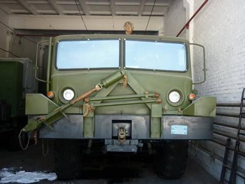
The stabilizers remain attached to the front of the vehicle but the probe and its' associated wiring are removed entirely.
The larger stabilizer with shock absorber at the peak of the A frame supports the vertical weight of the probe before attachment to the transport trailer. However the two smaller stabilizers are used exclusively to limit the left/right movement of the probe as the pusher tractor goes through the connecting process with the transport trailer. After attachment to the trailer they are disconnected and stowed during trasit.
I am not entirely sure just how I will choose to build my F/A.

#521
Kentucky, United States
Joined: April 13, 2011
KitMaker: 9,465 posts
Armorama: 8,695 posts
Posted: Saturday, April 26, 2014 - 08:14 AM UTC
I WILL TRY TO MAKE THIS A BRIEF DEPARTURE FROM THE PRIMARY TOPIC -
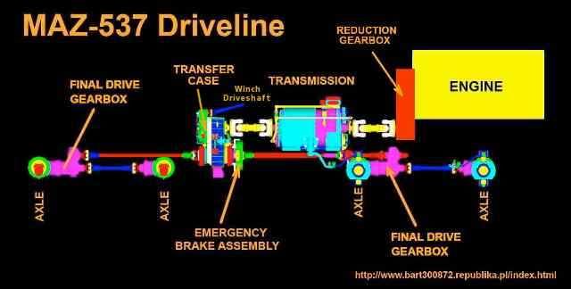
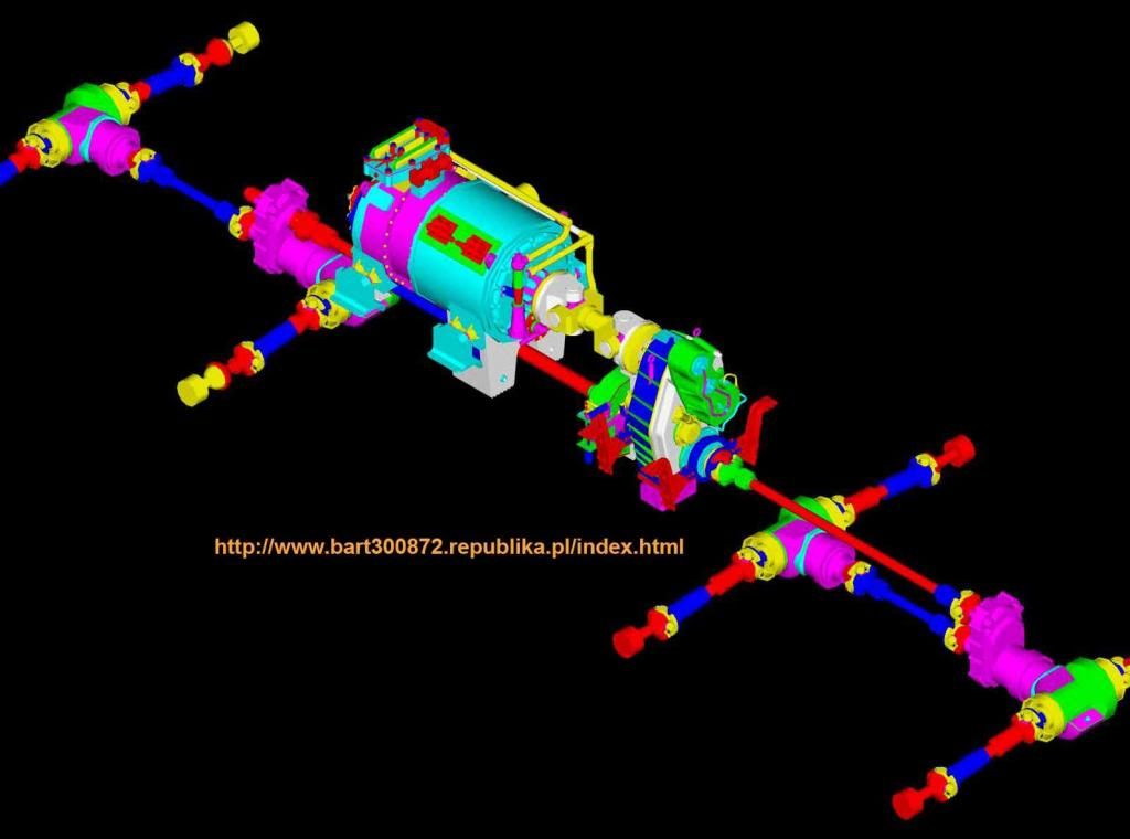
as I have stated elsewhere in other threads I am extremely disappointed with the MAZ driveline as Trumpeter has chosen to depict it which is nothing short of grossly incorrect AND mechanically impossible!
Here is the correct driveline layout for the MAZ-537:

#521
Kentucky, United States
Joined: April 13, 2011
KitMaker: 9,465 posts
Armorama: 8,695 posts
Posted: Saturday, April 26, 2014 - 08:18 AM UTC
And on the actual vehicle:
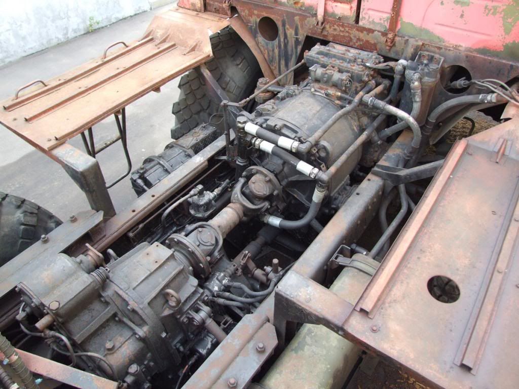
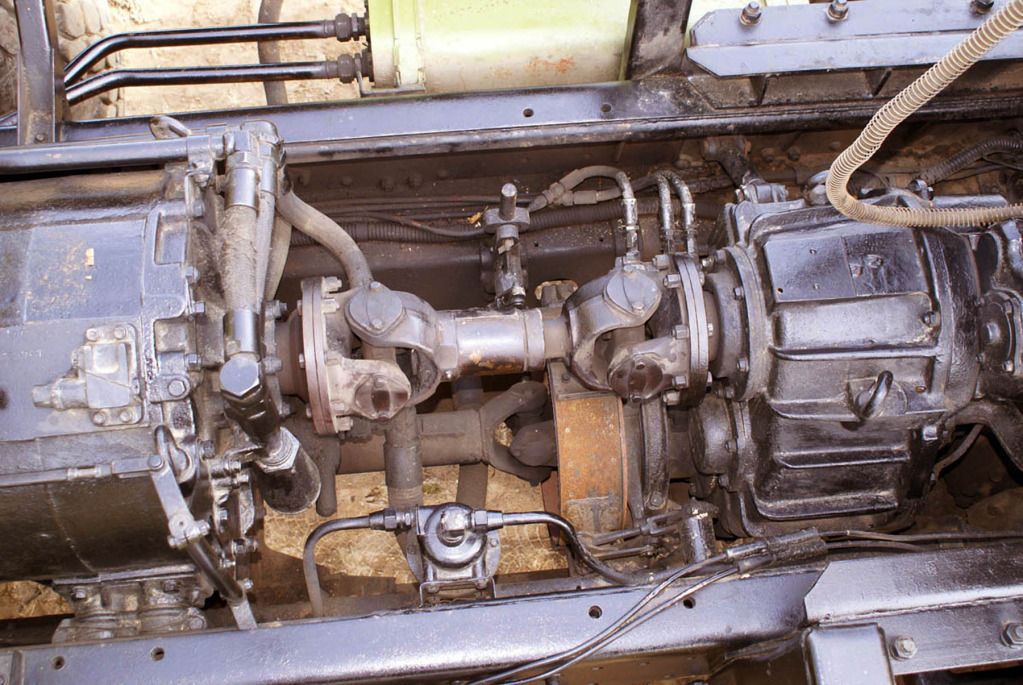

#521
Kentucky, United States
Joined: April 13, 2011
KitMaker: 9,465 posts
Armorama: 8,695 posts
Posted: Saturday, April 26, 2014 - 08:25 AM UTC
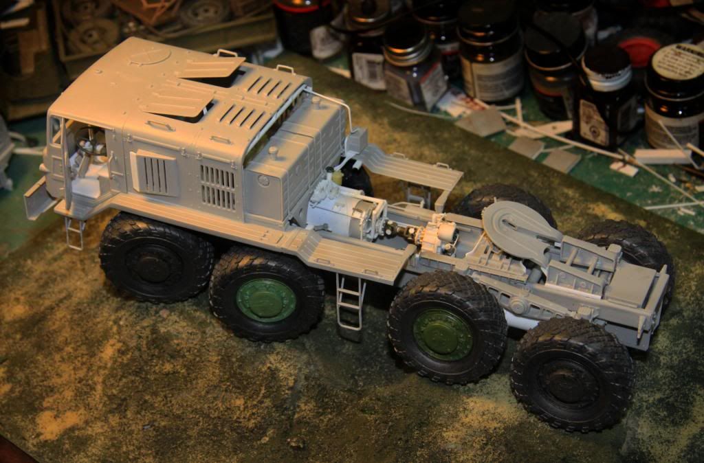
On my MAZ 537D towing tractor where the driveline is much more visably exposed I have chosen to correct these faults.
- The final drive units; there are two of them - one between the first and second axles and another between the third and fourth axles.
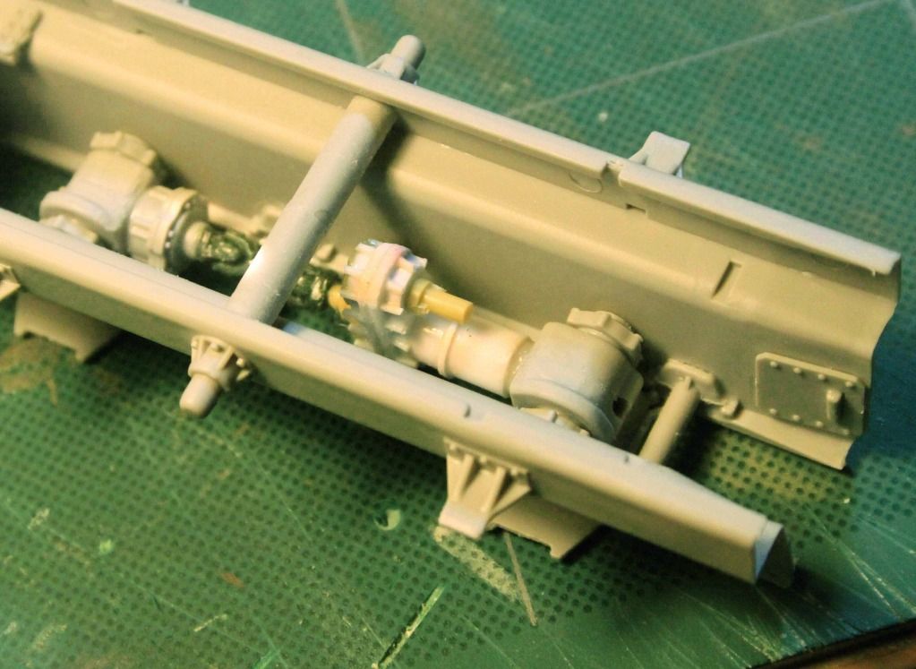
And here are the corrections to the transmission, transfer case and driveshafts:
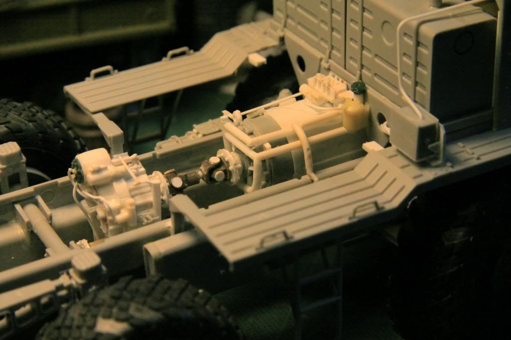

#521
Kentucky, United States
Joined: April 13, 2011
KitMaker: 9,465 posts
Armorama: 8,695 posts
Posted: Saturday, April 26, 2014 - 08:31 AM UTC
THE TRANSMISSION:

THE TRANSFER CASE:


#521
Kentucky, United States
Joined: April 13, 2011
KitMaker: 9,465 posts
Armorama: 8,695 posts
Posted: Saturday, April 26, 2014 - 08:52 AM UTC
Not sure I will be doing much of the correction shown above on my new MAZ F/A as very little of this work would be visible under the generator assembly and load box.

#521
Kentucky, United States
Joined: April 13, 2011
KitMaker: 9,465 posts
Armorama: 8,695 posts
Posted: Saturday, April 26, 2014 - 02:12 PM UTC
Just ordered the Tank Workshop resin wheel set for the 537 from Dragon Hobbies. I don't find anything wrong with the Trumpeter wheels and tires but it is the only way to get that spare!


#521
Kentucky, United States
Joined: April 13, 2011
KitMaker: 9,465 posts
Armorama: 8,695 posts
Posted: Sunday, April 27, 2014 - 06:55 AM UTC
A few more detail photos of the massive missile Transporter/Erector Trailer:


(Photo by Simon Burcon)

(Photo by Leonid Varlamov)


