Doing a little dry fit work on construction of the left hand control wiring:
Яusso-Soviэt Forum: Cold War Soviet Armor
For discussions related to cold war era Russo-Soviet armor.
Hosted by Jacques Duquette
MAZ 537 F/A Pusher Tractor
Posted: Saturday, January 17, 2015 - 07:22 PM UTC
Posted: Monday, January 19, 2015 - 09:16 PM UTC
Started on the forward "stinger" probe last night - photos to follow.
Posted: Tuesday, January 20, 2015 - 04:56 AM UTC
Couldn't find the 7/32nd" OD plastic tube I was shooting for so I went with brass of the same size.
I hope I won't end up regretting that choice.
(F.Y.I. The probe as shown above is overly long. This is done intentionally as I am unsure as yet just how much of its' length will be taken up by the receiver fitting.)
That small O.D. connector clevis comes from parts taken from a derelict Dragon Wagon found in my spares box. Interestingly it matches the actual MAZ part exactly.
So far so good.
Posted: Tuesday, January 20, 2015 - 05:57 AM UTC
The forward pusher fittings:
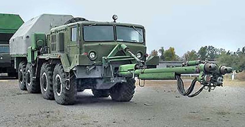
These three support struts are attached to the stinger probe only during the connection process while hooking the pusher tractor up to the trailer. They stabilize the stinger probe so the driver can maneuver the vehicle to attach the forward end of the probe into the trailer receiver. After the connection process is complete all three of these struts are detached from the stinger and stowed. The probe is then free to move with the trailer.
One could easily compare this forward probe to the human arm. The shoulder is at the bumper and when the support struts are removed this joint is free to go left-right / up-down. The elbow is located where the top and bottom cable shields meet. This middle joint is fixed and does not swing. Finally, just behind the forward connection device is the wrist and when the lone top mounted supporting strut is detached this joint is also able to swing freely.
Posted: Tuesday, January 20, 2015 - 02:37 PM UTC
SIDEBAR HERE - Again I am jumping around:
Would that I could step up and view what is in that load box!
We can see some storage lockers in the front of the box. Also a standard loading jib crane is stowed further back.
AND Two more items which I can only guesstimate;
#1. I expect that the unusual length (and extreme overhang) of the load box is governed by the need to be able to carry the stinger probe when not is use. (As when returning from the silo back to the assembly plant, awaiting the next missile assignment). So there is probably some sort of cradle fixture, rolling on a narrow track, that is required in order to load and store the stinger when not in use. I suspect this fixture runs down the center of the load box.
#2. This vehicle is clearly a ballast tractor, much like the MAZ-537/7310 airport tug or the WWII US Army M19 Diamond T ballast tractor. This vehicle would therefore require some sort of dead weight load to increase the tractive effort of the rear axles. I therefore suspect there to be four, six or possibly eight very large cast metal dead weights carried in this load box just as there is in the airport tug. (Do I see loops or lifting rings of these dead weights showing above the edge of the load box side walls?)
Any further thoughts anyone might care to offer on this subject would be greatly appreciated.
Posted: Tuesday, January 20, 2015 - 02:47 PM UTC
This was posted earlier in the thread but is this part of what we might see if we were to look down into the load box?
_______________________________________________________________________________
These are all shots taken from the MAZ-537A Airport Ballast Tractor.
Are similar ballast weights present in the F/A? It would seem plausable but we may never know:
_______________________________________________________________________________
These are all shots taken from the MAZ-537A Airport Ballast Tractor.
Are similar ballast weights present in the F/A? It would seem plausable but we may never know:
Posted: Wednesday, January 21, 2015 - 05:09 AM UTC
Jumping around again:
I wanted to improve on the kit fuel cans a bit so I went for the North Star Models 20 liter Jerry Cans.
Besides, I have a plan for a possible dio that involves needing extra fuel cans!
I can highly recommended this product!
(The nature of current day retail sales is amazing - I found these for sale on eBay, coming from Australia, they were manufactured in Latvia, and sold to a bloke in Kentucky, USA.)
Six Jerry cans in each set.
__________________________________________________________________________________
These Jerry Cans actually prove the Trumpeter offering to be fairly good though a bit on the small side. However with the North Star product you get the correct center seam, the spout/lid mechanism AND the stamped lettering on the side of the can. So again, Highly Recommended!
The North Star product is on the left - - - - - - - - - - - - - - The Trumpeter kit gas can is on the right
I wanted to improve on the kit fuel cans a bit so I went for the North Star Models 20 liter Jerry Cans.
Besides, I have a plan for a possible dio that involves needing extra fuel cans!
I can highly recommended this product!
(The nature of current day retail sales is amazing - I found these for sale on eBay, coming from Australia, they were manufactured in Latvia, and sold to a bloke in Kentucky, USA.)
Six Jerry cans in each set.
__________________________________________________________________________________
These Jerry Cans actually prove the Trumpeter offering to be fairly good though a bit on the small side. However with the North Star product you get the correct center seam, the spout/lid mechanism AND the stamped lettering on the side of the can. So again, Highly Recommended!
The North Star product is on the left - - - - - - - - - - - - - - The Trumpeter kit gas can is on the right
Posted: Wednesday, January 21, 2015 - 06:20 AM UTC
A bit more work completed on the stinger probe:
Using the same brass tubing as the main probe strut, I split this shorter piece of tubing down the middle with a Dremel tool, straightened out the sides and attached it to the main strut with Super Glue to form the first of the two probe cable guards.
Cut to length _________________________________________________ Lock in a vise and cut lengthwise
Use assorted tools to open up the tube into a "U" shape, sand and file until smooth and square then prime.
I have to admit I could not figure out how to avoid all the tool marks on the brass piece. So I will be applying many coats of primer and sanding in between in an attempt to hide these marks.
Posted: Wednesday, January 21, 2015 - 07:39 PM UTC
Posted: Wednesday, January 21, 2015 - 09:03 PM UTC
(Photo by Simon Bucan)
Click here to be transferred to Mr. Bucan's beautiful online portfolio of photography: http://www.brajdo.com/blog/
Posted: Thursday, January 22, 2015 - 09:02 AM UTC
PROBE PROGRESS:
The forward probe coming together - Cannot decide whether to add the other two smaller stabilizer struts to the probe or permanently attach them in the stowed position on the vehicle. Reference photos show them positioned either way.
Clearly there has to have been a ground guide person walking along to align the probe with the trailer mounted receiver as the pusher truck slowly advanced forward. (Hence the grab irons at the front end of the probe.) So the smaller left/right stabilizers are not totally necessary.
________________________________________________________________________________
Without horizontal stabilizers - - - - - - - - - - - - - - - - With horizontal stabilizers.
Right now my probe swings free, left to right and is removable. Using the horizontal stabilizers it would be a fixed rod sticking out the front of the model just asking to be knocked off! As it is right now it is a lot less likely to get knocked around and broken at shows. (Or on my display shelf for that matter!) Also it would mean not having to build and deal with four more small and delicate removable pin hinges on those small stabilizers. (And it appears the model would be just as correct either way!)
The forward probe coming together - Cannot decide whether to add the other two smaller stabilizer struts to the probe or permanently attach them in the stowed position on the vehicle. Reference photos show them positioned either way.
Clearly there has to have been a ground guide person walking along to align the probe with the trailer mounted receiver as the pusher truck slowly advanced forward. (Hence the grab irons at the front end of the probe.) So the smaller left/right stabilizers are not totally necessary.
________________________________________________________________________________
Without horizontal stabilizers - - - - - - - - - - - - - - - - With horizontal stabilizers.
Right now my probe swings free, left to right and is removable. Using the horizontal stabilizers it would be a fixed rod sticking out the front of the model just asking to be knocked off! As it is right now it is a lot less likely to get knocked around and broken at shows. (Or on my display shelf for that matter!) Also it would mean not having to build and deal with four more small and delicate removable pin hinges on those small stabilizers. (And it appears the model would be just as correct either way!)
Posted: Thursday, January 22, 2015 - 09:09 AM UTC
pgb3476
Texas, United States
Joined: March 11, 2007
KitMaker: 977 posts
Armorama: 976 posts
Joined: March 11, 2007
KitMaker: 977 posts
Armorama: 976 posts
Posted: Thursday, January 22, 2015 - 07:32 PM UTC
Stinger looks perfect.
Posted: Friday, January 23, 2015 - 04:06 AM UTC
Posted: Friday, January 23, 2015 - 09:59 AM UTC
heliman
New York, United States
Joined: June 14, 2010
KitMaker: 702 posts
Armorama: 604 posts
Joined: June 14, 2010
KitMaker: 702 posts
Armorama: 604 posts
Posted: Friday, January 23, 2015 - 09:17 PM UTC
amazing attention to detail Micheal! Ive alway been fond of the MAZ variants.
Jeff
Jeff
Posted: Saturday, January 24, 2015 - 12:21 AM UTC
Posted: Saturday, January 24, 2015 - 12:43 AM UTC
Was thinking about this as a possible paint color scheme for my model, aged/faded two tone green topside and black equipment color below decks. This I believe, was the original paint scheme at the time when the Ukrainian missile base was converted over to a Museum. The pale green paint came later!
Thoughts anyone?
Thoughts anyone?
Posted: Saturday, January 24, 2015 - 08:58 PM UTC
I'm afraid I bore rather easily when I work too long on one area so I jump around a lot to various parts of the model. (That's probably why I have so many in-process projects on my work bench. However I would like to take this project "all the way".)
Late last night I moved back to the generator deck. I did some work on the additional circuit boxes required back there. However I will still need to plan out a wiring cable scheme.
If some of these small boxes look familiar it is because they were lifted in whole or part from the old Dragon Scud kit. (I had the TEL equipment in my spares box due to my recent conversion of this model into the AA-60 Airport Fire Truck.)
(This model is still killing time resting on my workbench, darn it!)
Posted: Saturday, January 24, 2015 - 09:35 PM UTC
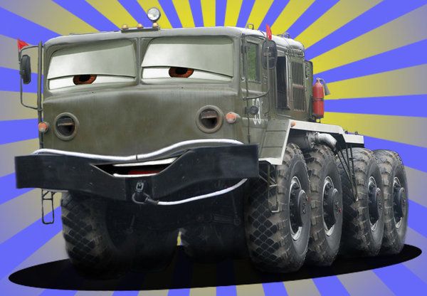
The second Disney "Cars" movie went on the International Auto Racing Circuit and involved international spies and foreign intrigue.
If only the movie had included a Russian component MAZZY here could have had a starring role!
(Illustration by S-a-p-p-e-r)
More of Sapper's military and fantancy artworks can be found at:
http://s-a-p-p-e-r.deviantart.com/
If only the movie had included a Russian component MAZZY here could have had a starring role!
(Illustration by S-a-p-p-e-r)
More of Sapper's military and fantancy artworks can be found at:
http://s-a-p-p-e-r.deviantart.com/
Posted: Sunday, January 25, 2015 - 05:22 AM UTC
Well as you know I built the other circuit boxes this week and it was time to complete the connecting wiring conduits between them.
In my life I have had to bend and install a bit of thin wall metal electrical conduit. My straight runs and corner bends
came out about as straight in 1 to 1 scale as the ones on my model! Making straight runs, bends and proper off-sets
is an art. Respect to any electrician that can do it right!
In my life I have had to bend and install a bit of thin wall metal electrical conduit. My straight runs and corner bends
came out about as straight in 1 to 1 scale as the ones on my model! Making straight runs, bends and proper off-sets
is an art. Respect to any electrician that can do it right!
pgb3476
Texas, United States
Joined: March 11, 2007
KitMaker: 977 posts
Armorama: 976 posts
Joined: March 11, 2007
KitMaker: 977 posts
Armorama: 976 posts
Posted: Sunday, January 25, 2015 - 05:54 AM UTC
Mazzy..lol. Nice plumbing.
Posted: Sunday, January 25, 2015 - 06:15 AM UTC
Posted: Tuesday, January 27, 2015 - 08:33 AM UTC
Posted: Saturday, January 31, 2015 - 03:24 AM UTC
On a related topic; the MAZ-537 series was originally built with duel, round canister type air filters custom to the MAZ, the two units mounted vertically between the engine and the forward firewall. Later these same MAZ trucks were modified to reduce field maintenance inventory requirements. The MAZ series now uses the same air filter enclosure and cartridges as the Russian tanks. The retrofit kit is shown here. (The front of the vehicle is to the right.)
If using the Verlinden resin tank engine
to provide an engine for your MAZ you
can utilize the Air Cleaner assembly
that comes in that set!
If using the Verlinden resin tank engine
to provide an engine for your MAZ you
can utilize the Air Cleaner assembly
that comes in that set!