MAZ 537 F/A Pusher Tractor

#521
Kentucky, United States
Joined: April 13, 2011
KitMaker: 9,465 posts
Armorama: 8,695 posts
Posted: Monday, January 05, 2015 - 09:01 PM UTC
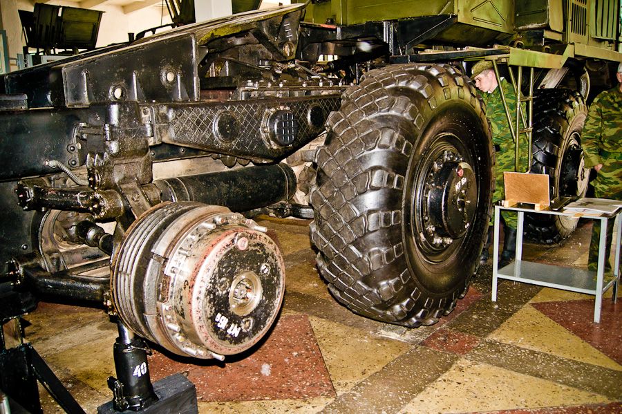
Interesting photo of the 537 found last night online showing the naked wheel gear hub and brake assembly - very compact!
Also as I had mentioned earlier this photo illustrates the large air tanks that should appear between the #3 and #4 axles.
Texas, United States
Joined: March 11, 2007
KitMaker: 977 posts
Armorama: 976 posts
Posted: Monday, January 05, 2015 - 09:57 PM UTC
Gregovich "I paint all my Models in 4BO Green" Beckman
Holder of the Knight's Cross, Hero of the Soviet Union, Dragon Slayer and Slinger of Massive BS.

#521
Kentucky, United States
Joined: April 13, 2011
KitMaker: 9,465 posts
Armorama: 8,695 posts
Posted: Tuesday, January 06, 2015 - 05:23 AM UTC
I included these air tanks in both my 537's. Hard to see but yes, they're in there!

Texas, United States
Joined: March 11, 2007
KitMaker: 977 posts
Armorama: 976 posts
Posted: Tuesday, January 06, 2015 - 07:07 PM UTC
Gregovich "I paint all my Models in 4BO Green" Beckman
Holder of the Knight's Cross, Hero of the Soviet Union, Dragon Slayer and Slinger of Massive BS.

#521
Kentucky, United States
Joined: April 13, 2011
KitMaker: 9,465 posts
Armorama: 8,695 posts
Posted: Tuesday, January 06, 2015 - 09:49 PM UTC
Thanks - the MAZ 537 actually uses welded air tanks with domed end caps but I liked the idea of the extra detailing offered by the riveted concave tank ends. What the heck!

#521
Kentucky, United States
Joined: April 13, 2011
KitMaker: 9,465 posts
Armorama: 8,695 posts
Posted: Wednesday, January 07, 2015 - 12:00 AM UTC

#521
Kentucky, United States
Joined: April 13, 2011
KitMaker: 9,465 posts
Armorama: 8,695 posts
Posted: Thursday, January 08, 2015 - 11:31 AM UTC
I know this is only a small step forward, but I sliced off the spring loaded "Jeep" hood style tie downs from the unused winch housing and added them to the top mounted tool box. (This a small detail missing off the toolbox on the basic kit as well.) Also the spare tire mechanism is just about finished.


#521
Kentucky, United States
Joined: April 13, 2011
KitMaker: 9,465 posts
Armorama: 8,695 posts
Posted: Thursday, January 08, 2015 - 11:39 AM UTC

#521
Kentucky, United States
Joined: April 13, 2011
KitMaker: 9,465 posts
Armorama: 8,695 posts
Posted: Friday, January 09, 2015 - 12:24 AM UTC
Generator housing seen end on, plan view.

To make the large diameter body curves needed to form the generator housing I glued thin sheet plastic around Evergreen plastic tubes of the correct diameter. The tubing becomes a perminent internal part of the otherwise hollow box structure.
Now to add the access door, air vents, panel strengthening ribs and wiring to the generator enclosure.

#521
Kentucky, United States
Joined: April 13, 2011
KitMaker: 9,465 posts
Armorama: 8,695 posts
Posted: Sunday, January 11, 2015 - 02:46 AM UTC
Added the access door and vent to the generator housing and made some progress on the explosion proof electrical enclosure.


#521
Kentucky, United States
Joined: April 13, 2011
KitMaker: 9,465 posts
Armorama: 8,695 posts
Posted: Sunday, January 11, 2015 - 09:02 AM UTC

#521
Kentucky, United States
Joined: April 13, 2011
KitMaker: 9,465 posts
Armorama: 8,695 posts
Posted: Sunday, January 11, 2015 - 11:57 PM UTC
AND FOR THE GEAR HEADS (like me) who might want to know what's inside the boxes . . .
The larger enclosure contains the electrical generator driven off the transfer case power take off. I would have thought this would be a DC generator as DC would give more mechanical power (and torque) per volt in these types of situations. However I read in more than one resource that the system produced AC. I question that; as an Alternating Current system in the 1960's would have required quite a bit of aditional electrical control equipment to regulate the generators in the two drive vehicles to keep them in phase with each other. A Direct Current system would require none of that.
The square panel on the front of the generator enclosure is a hinged access door for servicing. This door has a built in, top mounted, weather resistant air vent to allow heat from the generator to escape.
The box in front of and just above the generator is the enclosed contactor (read high voltage relay) that controls the flow of electricity from the generator to the active drive trailer. This enclosure is a cast metal structure built to contain any explosive ionized gases given off by the arc formed whenever the contactor opens or closes. Use of such a heavy cast metal or fibreglass enclosure would be MIL SPEC and SOP for any navel or military application. This enclosure has no access door and is only accessable for servicing by unbolting the entire front cover.
Below are photos of current day, US market, explosion-proof electrical enclosures -
Used wherever an exposed electric spark could cause an explosion in a hazardous gas fume environment:


I would say these items have not changed much in 50+ years, regardless of country of origin!
Texas, United States
Joined: March 11, 2007
KitMaker: 977 posts
Armorama: 976 posts
Posted: Monday, January 12, 2015 - 12:05 AM UTC
Gregovich "I paint all my Models in 4BO Green" Beckman
Holder of the Knight's Cross, Hero of the Soviet Union, Dragon Slayer and Slinger of Massive BS.

#521
Kentucky, United States
Joined: April 13, 2011
KitMaker: 9,465 posts
Armorama: 8,695 posts
Posted: Tuesday, January 13, 2015 - 01:22 AM UTC
Trying to figure out now what all the other assorted control boxes might be for.
In all likelihood the rear tractor was remotely controlled from the forward vehicle as to engine RPM, braking and control of the auxiliary generator. Lots of control wiring connections are present on the stinger probe.


#521
Kentucky, United States
Joined: April 13, 2011
KitMaker: 9,465 posts
Armorama: 8,695 posts
Posted: Tuesday, January 13, 2015 - 02:48 AM UTC
Receiver fitting on rear of the ballistic missile trailer:


#521
Kentucky, United States
Joined: April 13, 2011
KitMaker: 9,465 posts
Armorama: 8,695 posts
Posted: Tuesday, January 13, 2015 - 06:45 PM UTC
Of course one simple way around the cross phasing problem of having two AC generators feeding the same circuit would be to have the rear tractor power only the rear wheels of the trailer. The forward tractor would then power only the forward wheels which would keep the two circuits totally separated

#521
Kentucky, United States
Joined: April 13, 2011
KitMaker: 9,465 posts
Armorama: 8,695 posts
Posted: Thursday, January 15, 2015 - 12:40 AM UTC
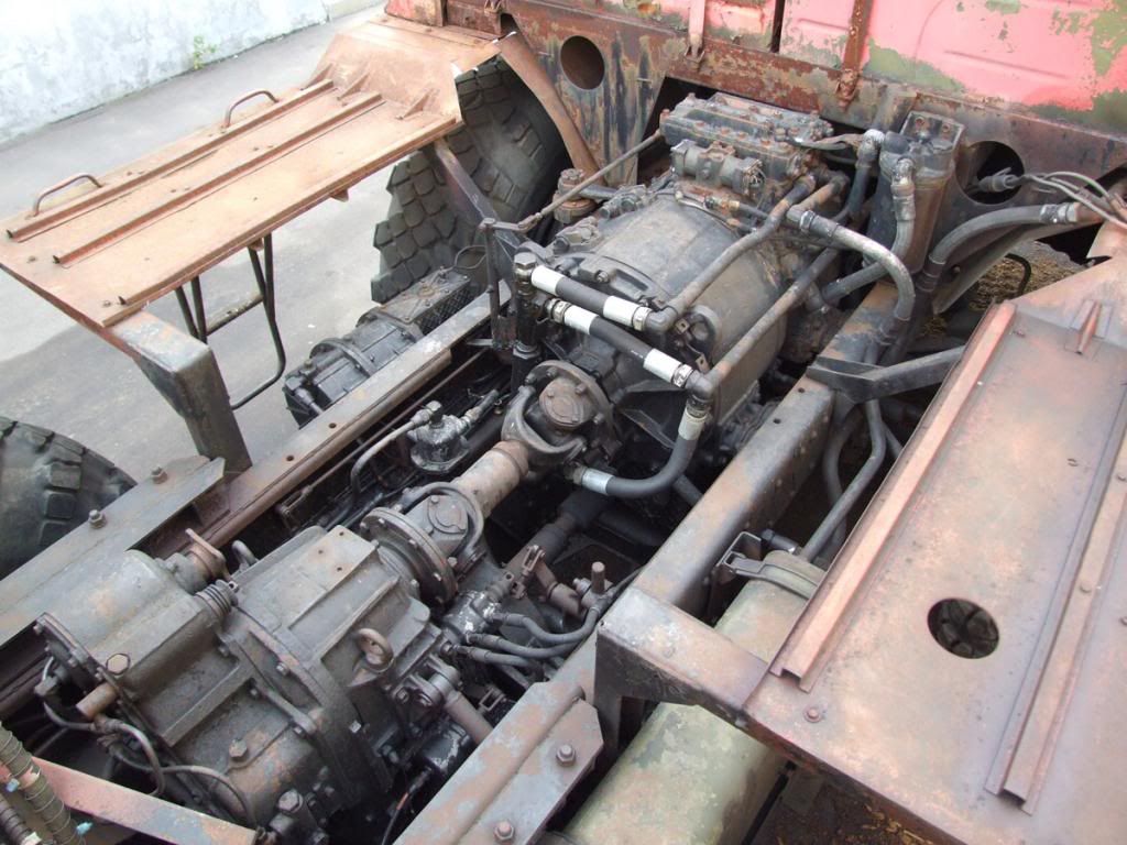
Going to be shifting over to plumbing and bolt head detail duty for the next few days. I will be adding details to the transmission and transfer case. I want to take some time working elsewhere while planning for the construction of the other electrical boxes and the wiring layout.

So far I have added the logic block to the top of the transmission and a number of oil hoses. More details to follow:
__________________________________________________________________________
As you can see I tend to like some complexity in a build. And I like my vehicles to be anatomically correct as well!
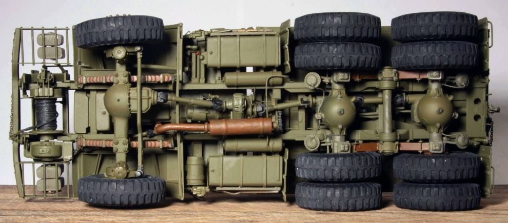
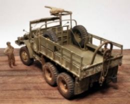
Scratch built Mack NO Artillery Tractor in 1/35th scale.
Build log on the Mack NO can be found at:
http://armorama.kitmaker.net/forums/196219&page=1
#521
Kentucky, United States
Joined: April 13, 2011
KitMaker: 9,465 posts
Armorama: 8,695 posts
Posted: Thursday, January 15, 2015 - 06:52 AM UTC
A little surprise here. It occurred to me that adding the three heavy power cables to the right side would be a very easy task so here we go . . . . A very straight forward slam dunk!


#521
Kentucky, United States
Joined: April 13, 2011
KitMaker: 9,465 posts
Armorama: 8,695 posts
Posted: Thursday, January 15, 2015 - 07:29 AM UTC
Overall progress photo as of 1/15/2015:


#521
Kentucky, United States
Joined: April 13, 2011
KitMaker: 9,465 posts
Armorama: 8,695 posts
Posted: Friday, January 16, 2015 - 07:22 PM UTC
I know I am jumping around but last night my thoughts turned to the toolboxes mounted at the rear, underneath the ballast box:

In the past I have always had trouble building large fuel tanks and boxes. It seems I can never quite get them exactly square.
I have tried building them out of solid blocks, out of stacks of solid bar stock and out of framed up hollow sheet plastic but they never turned out quite true. Then last night at my LHS I hit upon an idea. Cut them out using the new rectangular plastic tubing being offered by Evergreen and Plastastrut. Stack them up, sand them true and then cover them in sheet plastic.


#521
Kentucky, United States
Joined: April 13, 2011
KitMaker: 9,465 posts
Armorama: 8,695 posts
Posted: Friday, January 16, 2015 - 07:33 PM UTC
So I set up a crude cut-off saw on my work bench using my mitre box, hobby saw, a square and a small clamp. I then proceeded to chop out twelve fairly duplicate pieces of tubing.


#521
Kentucky, United States
Joined: April 13, 2011
KitMaker: 9,465 posts
Armorama: 8,695 posts
Posted: Friday, January 16, 2015 - 07:37 PM UTC
I glued them together and gave the ends a brief smoothing with some wet sand paper and I was ready to cover them in sheet plastic.
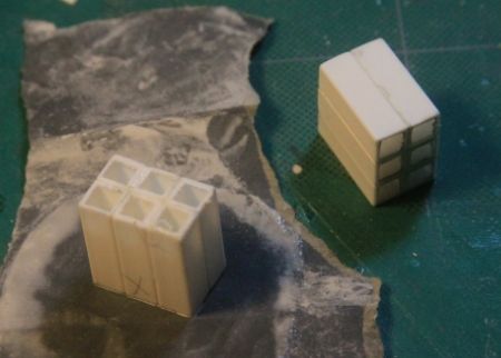
These sort of remind me of the racks for 50 cal. ammo cans that mount in the cab of the Dragon Wagon.

#521
Kentucky, United States
Joined: April 13, 2011
KitMaker: 9,465 posts
Armorama: 8,695 posts
Posted: Friday, January 16, 2015 - 07:42 PM UTC
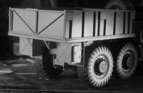
Add a little strapping, some rod to represent the strengthening ribs, doors, hinges, handles and there you have it! Two nicely square and true boxes and a plan for handling such problems in the future.

Texas, United States
Joined: March 11, 2007
KitMaker: 977 posts
Armorama: 976 posts
Posted: Friday, January 16, 2015 - 08:12 PM UTC
That's a great idea.....so, I assume your about 90% complete on the truck?
Gregovich "I paint all my Models in 4BO Green" Beckman
Holder of the Knight's Cross, Hero of the Soviet Union, Dragon Slayer and Slinger of Massive BS.

#521
Kentucky, United States
Joined: April 13, 2011
KitMaker: 9,465 posts
Armorama: 8,695 posts
Posted: Friday, January 16, 2015 - 11:50 PM UTC
Not so close to being done . . . still have the probe to build and the A frame over the load box. Plus I would like to do a serious detailing of the cab and there is the left side control wiring yet to do!
p.s. I am also planning to build some form of medium to low detail radiators for the hard to see but visible engine compartment. (Besides they will be good practice for finishing my MAZ-537 semi-tractor with full engine compartment detail!) Also perhaps building a low detail engine for this pusher tractor as well!
_______________________________________________________________________________
Engine compartment (so far) on my MAZ-537 semi-tractor:


