

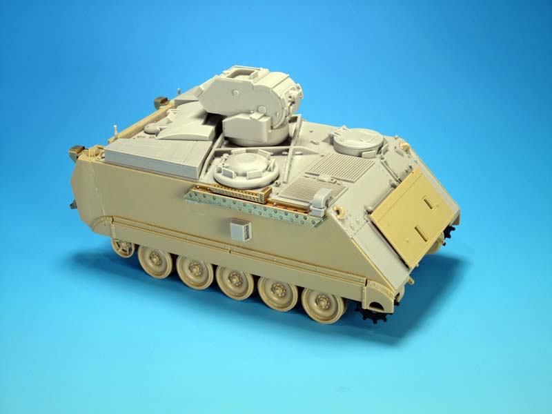
1⁄35M113 TUA Conversion Set
6
Comments
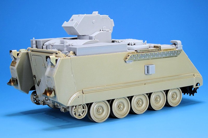
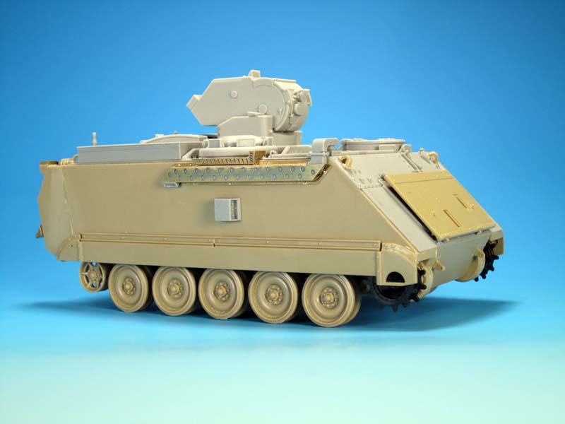
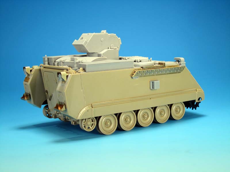
hull sides, exhaust and grouser racks
The exhaust was tackled next and is comprised of the following parts: 1. Exhaust hood (resin) 2. Extended exhaust pipe (resin) 3. Exhaust pipe cover (PE) 4. 2 x Exhaust cover supports (PE) 5. Crew heater extension (resin) 6. Crew heater exhaust pipe (resin) 7. Crew heater exhaust extension cover (PE) 8. Crew heater exhaust pipe cover (PE) 9. Various bolts (resin) That seems like a lot of parts for an exhaust, but it is with good reason, and this is another area of the conversion that modellers will have choices as to which version of the TUA they want to depict. Out of the box the conversion includes a version of the exhaust and heater exhaust that was used from the 1990s until retirement. This was not always the case and by trial and error the exhaust extensions were fabricated on the TUA. When the TUA first came into service only a slightly raised exhaust pipe was attached on the engine grille. This became an instant obstruction for the crew commander with billowing diesel exhaust drifting toward his hatch as well as the possible disruption of thermal sight pictures within the gunner's site. A field improvised solution was tried including an add-on piece of heat resistant exhaust hose hung over the hull side. This merely diverted the exhaust downward a short distance being moving back up to the hull. There was no extension for the crew heater exhaust as that time. The TUA without the exhaust extension or the small section of pipe would have been common in Germany from around 1989 into the early 1990s. A fabricated metal full hull length version was next with the exhaust pipe running to the end of the hull with a solid cover over it. This worked but likely greatly increased the TUA's thermal signature. The full length exhaust extension could be seen on Germany-based TUAs and UNPROFOR TUAs when they first deployed to Bosnia, but the solid extension was pulled off and replaced with the perforated version fairly quickly. The final version cut down the exhaust and replaced the solid cover with a perforated version as seen in this conversion. What is unique about the final version is that you can see the seven bolt holes on the hull where the solid extension piece was mounted along the rear portion of the hull. Legend may not have noticed this detail and it is not mentioned in the instructions. I did not add the bolt holes during the build but later in the build I will mark them so you will see where they should be. The perforated version as depicted in the kit was used in Bosnia and Croatia with UNPROFOR, Bosnia with IFOR, Kosovo with KFOR, and Canadian based TUAs. The assembly of the exhaust extensions and the guards should be pretty straightforward but there are things you need to be aware of. Clean-up of the resin parts took little time. Cut away the large casting blocks carefully so you don't lose any detail. Test fit the solid exhaust hood and extended exhaust so you will know how much to cut off or sand in order for the parts to fit properly on the engine deck and the exhaust extension. The same applies for the crew heater parts. The PE parts are awesome and look accurate compared to the real TUA except for a lack of small weld seams. Legend has bend marks on the PE parts to assist with shaping, but upon closer inspection it appears they put the bend marks on the reverse side. If you bend the PE parts on the bend marks inward you will assemble the parts backwards/inside out. So, you have to bend the parts the opposite way of the bend marks. This can cause confusion and make for some difficult lining up the proper bend locations. Once the part is bent into the correct shape they look great. Once they are attached to the hull and the resin bolts added they really start to make the hull look like a TUA. On the right hull side under the exhaust is part of the TCCCS. This stands for Tactical Command and Control Communications System. Canada upgraded its military radio equipment in the early 2000s with the Iris Digital Communications System. One of the externally visible components was the add-on communications box. Different vehicles mounted the box in different locations. On the TUA, when the box is mounted, it is on the right hull side. Some TUAs had them and others did not. There was also an additional circular communications attachment point that was positioned to the left of the box, if it was fitted. Again, not all TUAs had both components. The components allow for additional communication equipment attachments from outside the vehicle. Legend did not include the additional circular component. The single part is well detailed, a snap to clean up, and no issue to attach. Position the box half way between the bottom of the exhaust shroud and the top of the side skirts. The left edge lines up with the right of centre side skirt bolt.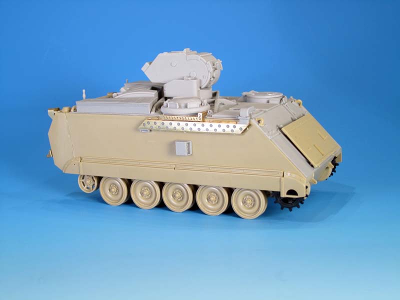
About the Author


Comments

As always Jason nice and precise work and assessment on this product and a good finished product.
NOV 29, 2014 - 08:00 PM
Excellent article, thank you for the detailed build information and great photos.
NOV 30, 2014 - 07:42 AM

A perfect example how the build article should look like. Thanks Jason for all the info provided and absolutely great photos.
Mario
NOV 30, 2014 - 01:21 PM


I just got mine and it's a great conversion. Wish they hadn't molded the TOW tubes sloped down though.
MAY 08, 2015 - 07:31 AM

Copyright ©2021 by Jason Bobrowich. Images and/or videos also by copyright holder unless otherwise noted. The views and opinions expressed herein are solely the views and opinions of the authors and/or contributors to this Web site and do not necessarily represent the views and/or opinions of Armorama, KitMaker Network, or Silver Star Enterrpises. All rights reserved. Originally published on: 2014-11-30 04:47:45. Unique Reads: 19130

WEB HOSTING BY


Copyright ©2021 Armorama and Kitmaker Network, a subsidiary of Silver Star Enterprises
All Rights Reserved. Please read our Conditions of Use and Privacy Policy.
All Rights Reserved. Please read our Conditions of Use and Privacy Policy.