

1⁄35M113 TUA Conversion Set
6
Comments
Jumping back to the hull front and looking down the final drive housings, wear bars are provided in PE. The wear bars were made of an aluminum alloy and standard on all Canadian M113s. Prominent weld beads are a common sight around the outside of the wear bars and would be easy to add with sprue.
On the left lower front hull spare track links are added. In the instructions it shows four track links attached to the glacis plate. I have seen anywhere from two to four track links attached in this location. The inaccuracy in the instructions comes from the use of standard M113 tracks instead of the Diehl tracks used on Canadian M113s. On Canadian M113s there are four post mounts used to hold the track links in place. The tops of the posts are tapped to receive attachment bolts and washers. The posts were not included by Legend in the conversion, and I was quite surprised by this as it is a very recognizable feature. Some well-placed styrene posts will solve the problem. To show the correct placement of the spare tracks I used two links from a set of plastic HKCW M113 Diehl tracks. I did not scratch the mounting posts for the review build. If the mounting posts were added, the PE washers would be added on top of the posts to replicate the bolt/washer combo.
On the top of the trim vane release attaches a small resin pull handle. Be careful with this piece and you may confuse it with the C6 GPMG barrel! Two mirrors are added to the upper hull sides. The brackets are provided moulded on the hull and should be drilled out to receive the wire arms. The mirrors themselves clean up easily. On the TUAs the mirrors used are the same as on the Leopard 1. They can be seen either with the rubber shroud, or without, as provided in the kit. I used the conversion supplied 0.5 mm brass wire to form the mirror arms. It will be down to your discretion as to placement, or if you want to attach the mirrors to the arms themselves.
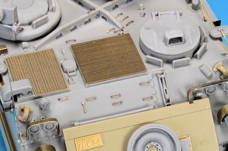
On the hull top two great looking PE engine grills are provided. These PE parts fit like a glove and add a great dimension to the details of the conversion. The turn signals are a feature unique to Canadian M113s and have evolved over the years. On the TUA the larger taillight style is used with a rounded guard. The turn signals are very nicely cast in resin. A small PE mount is provided and must be bent carefully so that when attached to the glacis plate the vertical portion sits at 90 degrees to the ground. The resin lights attach to the centre and two resin bolts are attached to the base portion. The rounded guards must be bent to shape and I used my Mission Models multi-tool to get a consistent bend. The rounded portion must be the same size as the base attached to the hull. On the real TUA wires extend from the back of the mount and attach to socketed leads from the main headlights.
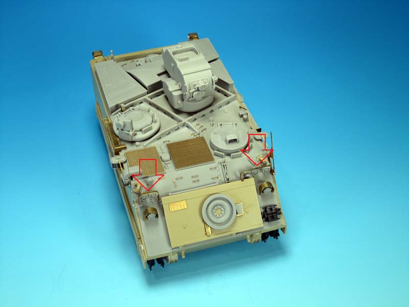
Placement of the mounts is very important. There are no guidelines on the hull and Legend provides images in the instructions. Reviewing my TUA references, I used a measurement of 18 millimetres from the bottom edge of the resin hull to the bottom of the mount attached to the hull to gauge placement locations. I have not yet attached the headlights, the IR lights, or the blackout drive light. In preparation I did drill out the attachment mounts provided on the resin hull. In reality the mounts are a bracket attachment but these will do just fine.
In summary, all of the details added during this portion except for the GPS antenna are standard to all TUAs. Depending on the TUA an actual antenna mount could be seen mounted on the base plate instead of the GPS antenna on earlier TUAs.
wire cutters, headlights, more tie downs
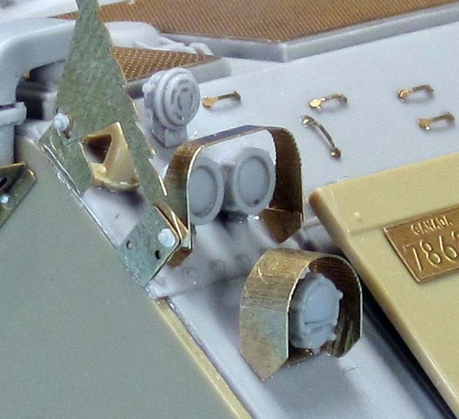
The wire cutters are fine sub-assemblies in themselves with each consisting of five PE parts and four resin bolts. Take the time to study the parts, the instructions, and where the mounts attach to the hull. The right and left mounting points on the hull are slightly different due to the engine deck on the right side, so take care before attaching parts. On the left hull side there is a small gap to fit the mounts, but on the right side it is a bit more delicate as there is only a small amount of room to attach the mounts on the resin upper hull. This image shows the mounting brackets and the assembled wire cutter on the left side. The wire cutter itself is essentially sandwiched between inner and outer brackets. The Legend instructions have you run a small rod of sprue between the outer bracket, the wire cutter, and the inner brackets on each side in order to align the parts. After some trials I ended up heating and stretching some sprue and then heating the end to create a small rounded end. When the sprue was slid through the parts it held in place on one end to allow the other parts to be aligned and glued. Once in place the sprue ends were trimmed and the large resin bolts labelled "A" added to both sides of the mounts. On the real TUA the wire cutters are designed to have the attachment bolts removed so the wire cutters could be pivoted down during firing so as to not interfere with the missile guidance wires. It will be up to you as to how to pose the wire cutters on your TUA. The resin headlights, IR lights, and blackout drive light were simple enough to clean up and mount. On the actual M113 series there is a myriad of wiring that connects to each light and runs back to common points above the lights. Legend does not mention any of the wiring but it is a detail that should be added. I suspected the headlight guards were not going to be a piece of cake. There is no bending jig provided and you are left to use the instruction images and your best guess as to how to size the guards for bending. In reality the left and right guards are actually bent slightly differently. The left guard has the curves and then runs straight down on both sides. The right guard has the curves, then runs straight down, and then has an inward curve on both sides... sort of like an 'S' shaped taper. The instructions do not indicate this shaping. On the bottom on the PE guard legs are small PE mounts that attached to the PE guards so that they will sit properly on the highly angled glacis plate. Pairs of resin bolts attach to the outsides of each PE guard. You have to love the M113s for having lots of tie downs. I added 15 more PE tie downs to the upper hull and the glacis plate area.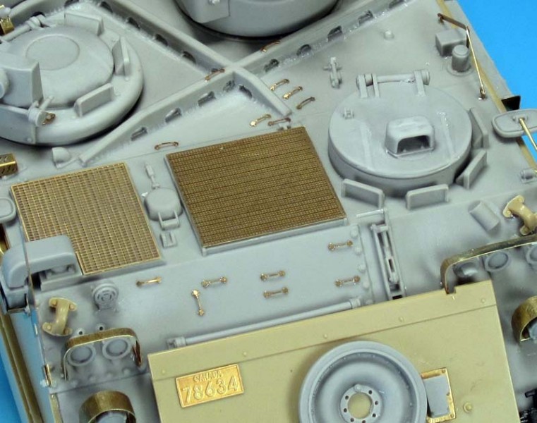


About the Author


Comments

As always Jason nice and precise work and assessment on this product and a good finished product.
NOV 29, 2014 - 08:00 PM
Excellent article, thank you for the detailed build information and great photos.
NOV 30, 2014 - 07:42 AM

A perfect example how the build article should look like. Thanks Jason for all the info provided and absolutely great photos.
Mario
NOV 30, 2014 - 01:21 PM


I just got mine and it's a great conversion. Wish they hadn't molded the TOW tubes sloped down though.
MAY 08, 2015 - 07:31 AM

Copyright ©2021 by Jason Bobrowich. Images and/or videos also by copyright holder unless otherwise noted. The views and opinions expressed herein are solely the views and opinions of the authors and/or contributors to this Web site and do not necessarily represent the views and/or opinions of Armorama, KitMaker Network, or Silver Star Enterrpises. All rights reserved. Originally published on: 2014-11-30 04:47:45. Unique Reads: 19130

WEB HOSTING BY


Copyright ©2021 Armorama and Kitmaker Network, a subsidiary of Silver Star Enterprises
All Rights Reserved. Please read our Conditions of Use and Privacy Policy.
All Rights Reserved. Please read our Conditions of Use and Privacy Policy.