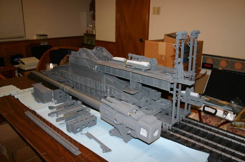
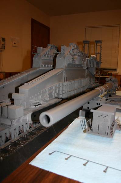
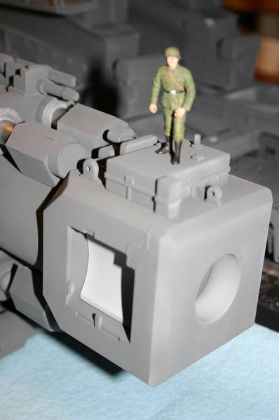
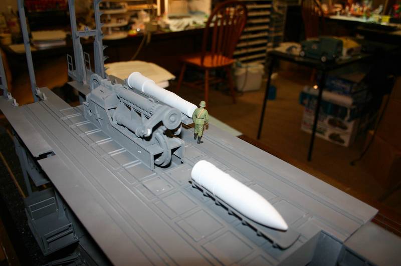
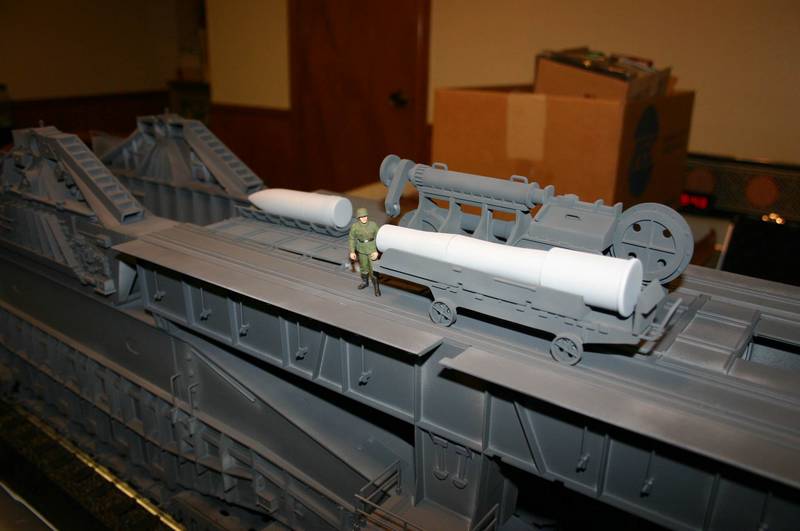
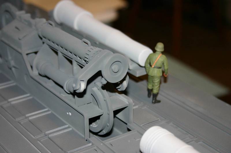
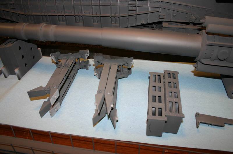
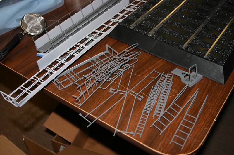
Found something new.Looking at the wartime pictures,above the center of the rail truck,you DO NOT see the triangular doohickey sticking out of the sides of the main gun mount.
These parts.
They do exist on some of the assembly of the gun pictures in the instruction booklet. I am guessing they were part of the equiptment used to tie off/mount pulleys to move larger parts around.
Armor/AFV
For discussions on tanks, artillery, jeeps, etc.
Hosted by Darren Baker, Mario Matijasic
1/35 Scale Rail Gun Dora in Progress
TankCarl
Rhode Island, United States
Joined: May 10, 2002
KitMaker: 3,581 posts
Armorama: 2,782 posts
Joined: May 10, 2002
KitMaker: 3,581 posts
Armorama: 2,782 posts
Posted: Saturday, July 21, 2007 - 02:12 AM UTC
Posted: Saturday, July 21, 2007 - 02:32 PM UTC
To Late! Already on
I'll start primer painting Sunday. Will have some parts with Pz grey on it.
Day by Day Week by Week It took 6 weeks to assemble the real thing - It may take me longer.
Tom Moon
I'll start primer painting Sunday. Will have some parts with Pz grey on it.
Day by Day Week by Week It took 6 weeks to assemble the real thing - It may take me longer.
Tom Moon
KingOfBattle
California, United States
Joined: July 17, 2007
KitMaker: 6 posts
Armorama: 5 posts
Joined: July 17, 2007
KitMaker: 6 posts
Armorama: 5 posts
Posted: Saturday, July 21, 2007 - 07:06 PM UTC
Quoted Text
This was discussed in another thread and it seems that the gent who posted that comment had measure the barrel included the breech which had put his measurements out. I've compared mine to the various historical pics and it looks OK - also I would be amazed if Soar Art got something as basic as that wrong considering the investment they must have in this monster.
Thanks for clearing that up. When I first read that elsewhere I was kind of bummed out. I've bought the kit and the accessories. Like you, I thought, no way Soar Art messed up on that. But I guess stranger things have happened.
Manuelke
Limburg, Netherlands
Joined: November 06, 2006
KitMaker: 2,714 posts
Armorama: 36 posts
Joined: November 06, 2006
KitMaker: 2,714 posts
Armorama: 36 posts
Posted: Saturday, July 21, 2007 - 08:41 PM UTC
This thing is huge. I link this building and other building treats on the armorama forum. Do you that building the Dora, have so much space to display this kit.
I will keep follow this and all the other dora treats, because i like this kit, but for me it is to big.
Best Regards, Manuel
I will keep follow this and all the other dora treats, because i like this kit, but for me it is to big.
Best Regards, Manuel
Posted: Sunday, July 22, 2007 - 03:28 PM UTC
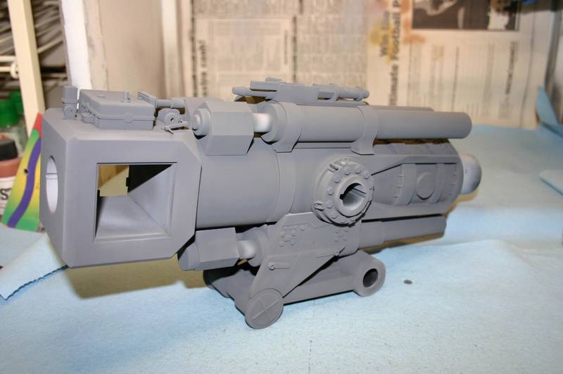
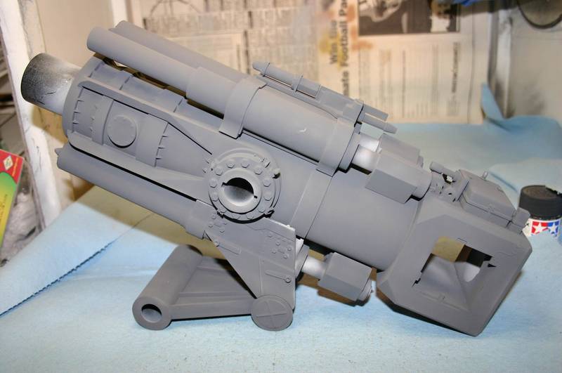
Here are some photos of the progress that has been made this week.
This is the right side of the barrel and breech block with base coat of Pz Grey.
This is the left side of the barrel
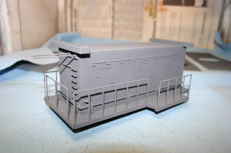
This is the generator housing with base coat
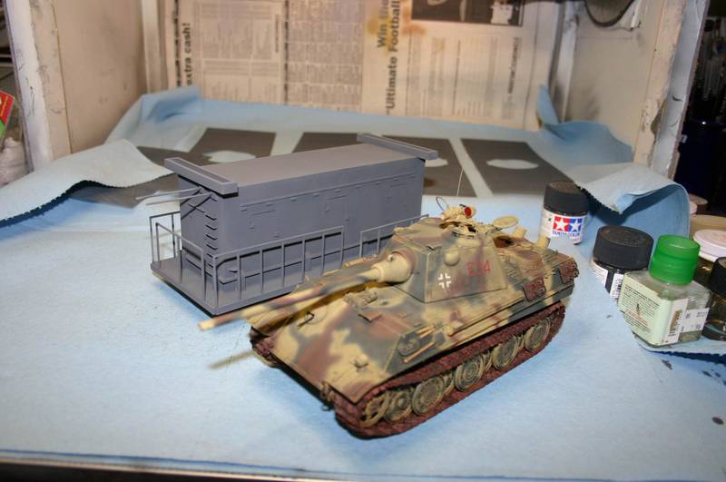
This is the generator housing next to a panther to show the size of the smallest major assemble of the DORA
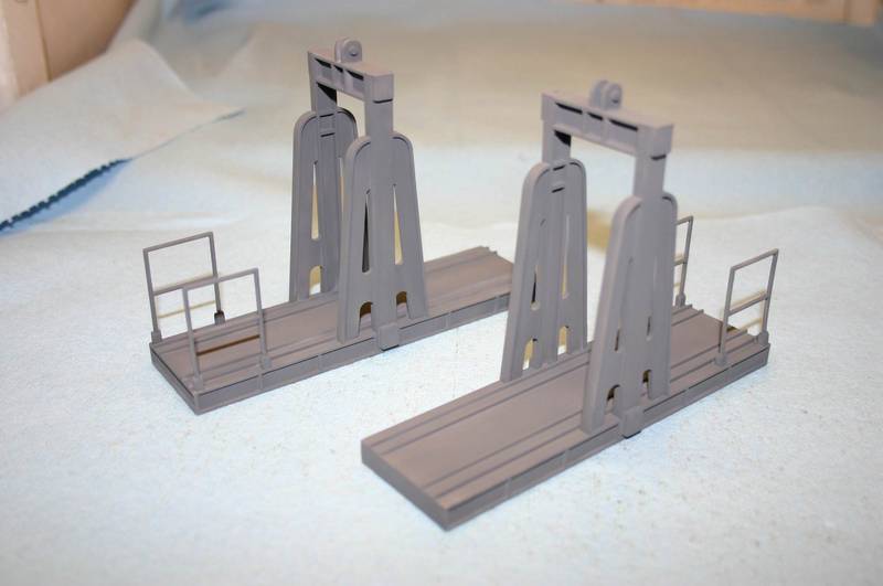
These are the munitions elevators painted with base coat only
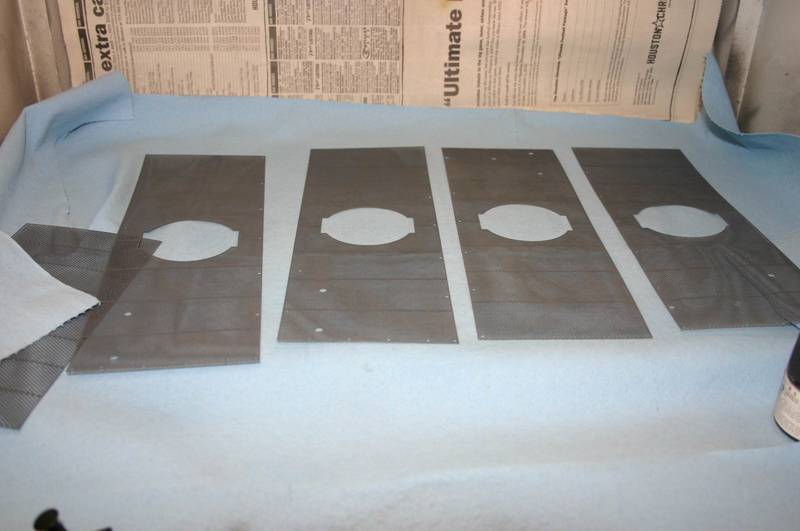
These are the PE Screens with primer and base coat
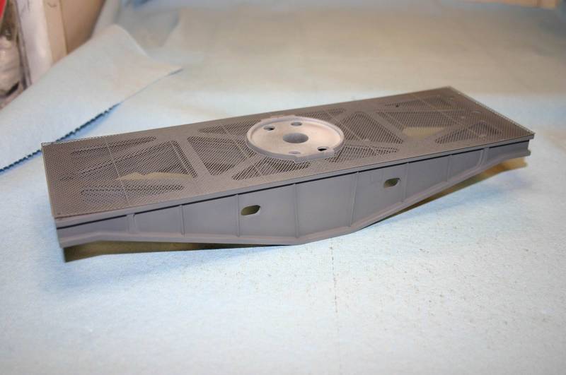
This is the Truss with the PE Screen dry fitted
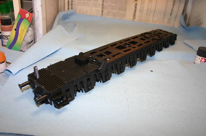
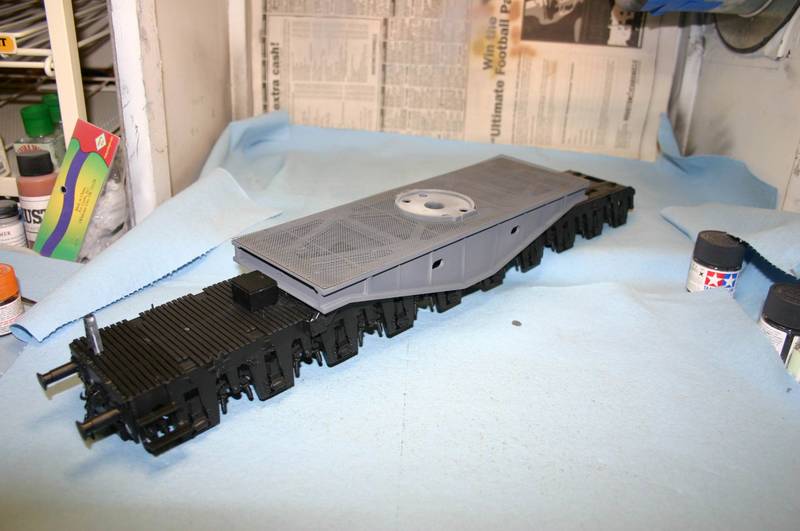
This is a partially completed rail car
Partially completed rail car with truss
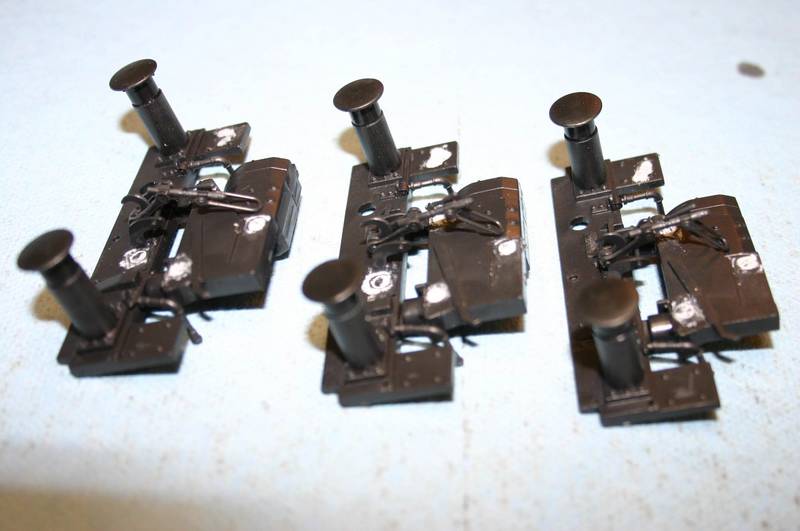
Rail car ends ready for soapy water wash and primer
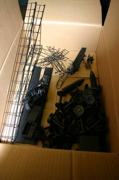
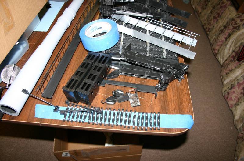
More parts for the bath and primer
Even more parts for the bath and primer
Will have more as progress is made
Tom Moon
Houston, Texas
TankCarl
Rhode Island, United States
Joined: May 10, 2002
KitMaker: 3,581 posts
Armorama: 2,782 posts
Joined: May 10, 2002
KitMaker: 3,581 posts
Armorama: 2,782 posts
Posted: Monday, July 23, 2007 - 01:46 AM UTC
Nice progress,Tom. Mind which PE floor goes on which truss.The trusses for the rear of the gun only have 1 equiptment box on them.
Posted: Monday, July 23, 2007 - 03:54 AM UTC
Quoted Text
Nice progress,Tom. Mind which PE floor goes on which truss.The trusses for the rear of the gun only have 1 equiptment box on them.
After I have weathered the trusses, I was going to use the railings and the other boxes that have pins that go thru the screens to "glue" the screen down. Have you finished this section yet? If so, how did you attach the screen to the truss?
Thanks,
Tom
Erdinger
Baden-Württemberg, Germany
Joined: September 23, 2006
KitMaker: 2 posts
Armorama: 1 posts
Joined: September 23, 2006
KitMaker: 2 posts
Armorama: 1 posts
Posted: Monday, July 23, 2007 - 05:04 AM UTC
Quoted Text
Gents. I got my Dora kit a few days ago. Man, this thing is GIGANTIC ! I will be watching this thread (and a few others) closely. My big question right now is, are there any good online sources for wartime photos of the Dora ? (other then YT). All I have for references is the Squadron book on WWII German Railguns. Other then that, all I have are a few well-known shots, but they lack any detail that would be usefull in building this fantastic model !
Cheers !!
Robert
Robert, there is a German book that has a lot of good pics of a Dora being assembled. The title is "Deutsche Eisenbahngeschütze", written by Gerhard Taube. Maybe you have luck on the big "A", the ISBN number is 3-613-01352-5.
Regards,
Thomas
TankCarl
Rhode Island, United States
Joined: May 10, 2002
KitMaker: 3,581 posts
Armorama: 2,782 posts
Joined: May 10, 2002
KitMaker: 3,581 posts
Armorama: 2,782 posts
Posted: Monday, July 23, 2007 - 10:23 AM UTC
Tom,I put the screens on early with some super glue.I added the railings and appropriate boxes,then painted them in the base color.
Posted: Saturday, July 28, 2007 - 01:56 AM UTC
I have been out of town for 3 days but will have some more photos of the weekends progress.
Last night I sprayed the primer on most parts and now I'm working on the rail cars.
I should have them finished this weekend and will start major assembly shortly.
Tom
Last night I sprayed the primer on most parts and now I'm working on the rail cars.
I should have them finished this weekend and will start major assembly shortly.
Tom
Posted: Sunday, July 29, 2007 - 03:57 PM UTC
Here are some new photos of the weekends work.
This is an overall shot with the mainframe in dry fit on the semifinished railcars.
This is looking down the barrel.
This is a close up of the Breech block
This is a view of the Loading area looking toward the rear of the gun.
This is a view of the Loading area looking toward the front of the gun.
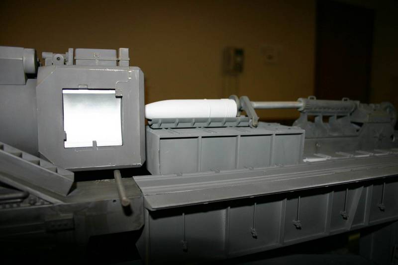
Close up of the Loading device and the powder charge.
Miscellaneous in between parts to hold the two mainframes together.
Miscellaneous ladders and walkways
Will have more as I finish the painting and assembly.
Tom Moon
f1matt
Manitoba, Canada
Joined: August 13, 2006
KitMaker: 1,021 posts
Armorama: 805 posts
Joined: August 13, 2006
KitMaker: 1,021 posts
Armorama: 805 posts
Posted: Sunday, July 29, 2007 - 05:42 PM UTC
I don't think I would ever have the patience to get something like this done. I mean painting it alone? All those nooks and crannies. Well I will definately keep following this one. I love seeing the foot soldier for scale next to it. I can't believe this thing really existed. Must be a bad joke. Maybe they got the scale wrong when producing the kit. Put the decimal in the wrong spot or smething?
TankCarl
Rhode Island, United States
Joined: May 10, 2002
KitMaker: 3,581 posts
Armorama: 2,782 posts
Joined: May 10, 2002
KitMaker: 3,581 posts
Armorama: 2,782 posts
Posted: Monday, July 30, 2007 - 04:40 AM UTC
Tom,
Nice job so far.In the group of railings,the one unit with the small PE screen,should fit on the main frame,with the "hinged" floor plate angling up onto the flooring running along side the trunnion mount.Having that small floring section level may cause fit problems.If you made it hinged on the 2 "D" parts,you'll be good to go.
As far as subassemblies for painting go,that;s about how I am planning on breaking it down.
gbkirsch
Ohio, United States
Joined: June 04, 2005
KitMaker: 627 posts
Armorama: 455 posts
Joined: June 04, 2005
KitMaker: 627 posts
Armorama: 455 posts
Posted: Monday, July 30, 2007 - 06:01 AM UTC
Amazing looking model!!!
Mojo
Ontario, Canada
Joined: January 11, 2003
KitMaker: 1,339 posts
Armorama: 637 posts
Joined: January 11, 2003
KitMaker: 1,339 posts
Armorama: 637 posts
Posted: Monday, July 30, 2007 - 10:15 AM UTC
Just exactly how big were the shells for this thing??
*EDIT* Just answered my own question.. 80cm or 2' 8"
http://www.vincelewis.net/dora.html
Dave
*EDIT* Just answered my own question.. 80cm or 2' 8"
http://www.vincelewis.net/dora.html
Dave
04090
England - East Anglia, United Kingdom
Joined: September 13, 2006
KitMaker: 257 posts
Armorama: 168 posts
Joined: September 13, 2006
KitMaker: 257 posts
Armorama: 168 posts
Posted: Monday, July 30, 2007 - 10:35 AM UTC
04090
Hi
it looks very big i only hope you have the loco to pull it
looking forward to the end product,
yours cyril
Hi
it looks very big i only hope you have the loco to pull it
looking forward to the end product,
yours cyril
bucko
Massachusetts, United States
Joined: January 15, 2006
KitMaker: 38 posts
Armorama: 24 posts
Joined: January 15, 2006
KitMaker: 38 posts
Armorama: 24 posts
Posted: Tuesday, July 31, 2007 - 11:32 AM UTC
I can't wait to see how that comes out. look's good so far.
trahe
Virginia, United States
Joined: April 03, 2006
KitMaker: 1,158 posts
Armorama: 950 posts
Joined: April 03, 2006
KitMaker: 1,158 posts
Armorama: 950 posts
Posted: Wednesday, August 01, 2007 - 01:22 AM UTC
Tom,
Looks great so far. It's a good thing you live in Texas, you'll need that much space to display that monster!
Posted: Friday, August 03, 2007 - 02:51 AM UTC
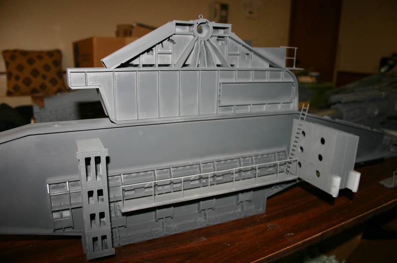
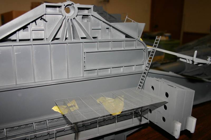
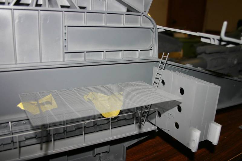
Part N2 walkway placement question, along with ladder placement
This is a photo of where I believe the N2 walkway should go.
This is a photo of the front area with the upper walkway and screen cover with ladder in the upper position as indicated by the kit instructions step 30.
This is a photo of the front area with the upper walkway and screen cover with ladder in the lower position.
Which do you think is the correct ladder position?
Thanks,
Tom Moon
Target_J
Kuala Lumpur, Malaysia
Joined: December 08, 2004
KitMaker: 145 posts
Armorama: 63 posts
Joined: December 08, 2004
KitMaker: 145 posts
Armorama: 63 posts
Posted: Friday, August 03, 2007 - 04:00 AM UTC
Hi Tom,
I have been building the Dora too. It was pointed out to me that assembly no.20 and assembly no. 18 might have been the wrong way round. No.20 should go to the back while no.18 should go to the front.
The following was pointed out to me by Mr. Clavs Hoffmann:
If you look at the instructions, on page 5.
Picture 2 you can see the front support between the 2 mainframes. This part is flat on the top and not sloped as steep 20. In front of this there is a thread plate, maybe part of PE no. V3.
Picture 3 shows step 20, on this you can see it is written, "Liker Träger, Hinten", so that is left to the rear.
TankCarl
Rhode Island, United States
Joined: May 10, 2002
KitMaker: 3,581 posts
Armorama: 2,782 posts
Joined: May 10, 2002
KitMaker: 3,581 posts
Armorama: 2,782 posts
Posted: Friday, August 03, 2007 - 10:24 AM UTC
Tom,did you see these? On the trunnion mounts.They weren't called out in the instructions.There are 5 parts B9 here.
Posted: Saturday, August 04, 2007 - 12:36 PM UTC
Quoted Text
Hi Tom,
I have been building the Dora too. It was pointed out to me that assembly no.20 and assembly no. 18 might have been the wrong way round. No.20 should go to the back while no.18 should go to the front.
The following was pointed out to me by Mr. Clavs Hoffmann:
If you look at the instructions, on page 5.
Picture 2 you can see the front support between the 2 mainframes. This part is flat on the top and not sloped as steep 20. In front of this there is a thread plate, maybe part of PE no. V3.
Picture 3 shows step 20, on this you can see it is written, "Liker Träger, Hinten", so that is left to the rear.
I have reviewed the instructions and the photos.
1. the Step 18 boxes are two pieces and that goes with photo 3 on page five.
2. The boxes are probably misshaped and should be of trapizoid instead of rectangular.
3. Step 20 box is one piece and corresponds to Photo 2 on page 5.
So i'm going to assemble as the instructions call for.
If you have additional information that could change my opinion please post it.
Regards,
Tom Moon
Posted: Saturday, August 04, 2007 - 12:46 PM UTC
Carl,
I did notice these extra handwheels and have prepared for them.
I have a different question for you and anyone else who is building this model.
I have been dry fitting the gun into the mounts of the 2 mainframes.
In step 6 on page 20 it shows part O18 being mounted with the flange pointed toward the frame.
This is a photo of the pieces held together with a clamp.
This is a photo with the flange pointed toward the gun.
It looks better with the flange pointed toward the gun.
Do you or anyone else have a idea as to which way it should go?
Another observation is that the Pushing device in step 16 page 30 when placed in the loading platform recess stands too tall. The extension arm will not engage a shell that is in the center tray. The 1/144 scale model I built last year depicts this piece to sit much lower. I'm considering removing the wheels and wheel frames (you can't see them anyway) to lower the device. Any comments?
Thanks,
Tom Moon
Posted: Saturday, August 04, 2007 - 02:11 PM UTC
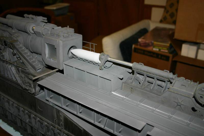
The center platform is adjustable in height. As these photos show, in the raised position the shell is at the correct height to be inserted into the gun which is in a horizontal position. Therefore the pushing device is in the correct configuration with the wheels attached.
Now I have to determine which position to show the center platform
1. Raised for loading with the barrel in the horizontal position
2. Lowered for firing with the barrel in the up position.
Probably in the Lowered position with the barrel in the firing position. It would be more impressive.
Tom Moon
Target_J
Kuala Lumpur, Malaysia
Joined: December 08, 2004
KitMaker: 145 posts
Armorama: 63 posts
Joined: December 08, 2004
KitMaker: 145 posts
Armorama: 63 posts
Posted: Saturday, August 04, 2007 - 04:28 PM UTC
Tom,
I'll be building mine with the flange pointed toward the frame. I was searching for pictures to see which direction they should point but have failed to find and good references.
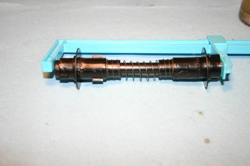
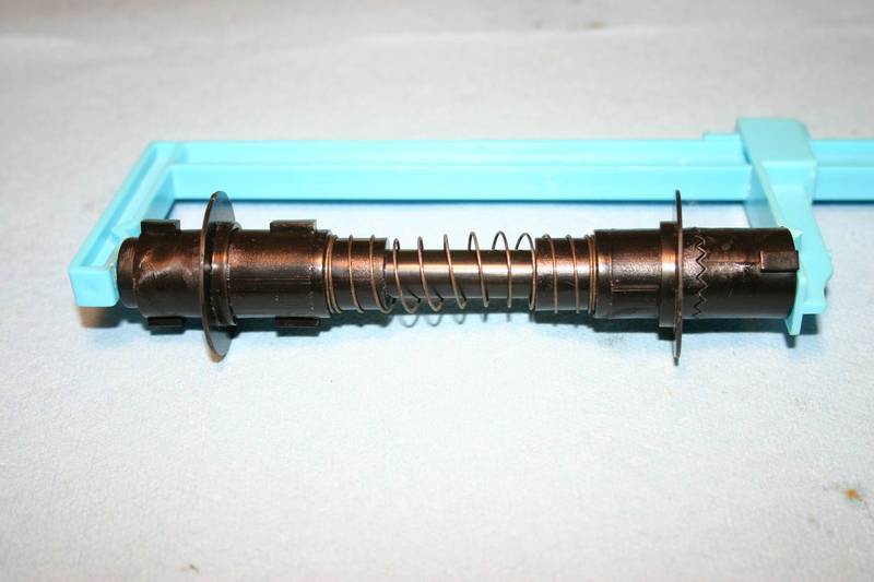
In the test fitting I did, it seams that the barrel doesn't lock into position if you want to position it at an elevated position. Is it supposed to be able to be posed at various elevations without fixing it permanently using glue? What use is the spring?
Jeremy