My first HEMTT - the Italeri LHS
Florida, United States
Joined: May 16, 2002
KitMaker: 17,694 posts
Armorama: 13,742 posts
Posted: Tuesday, November 15, 2016 - 09:04 PM UTC
Quoted Text
H.P. - Very nice detail shots towards the end of the post of a HEMTT A4 PLS!
Actually, the latest version of the PLS is the A1; i.e. M1074A1/M1075A1. It has most of the same features as the HEMTT A4 and is the same basic updated version. There was never an A2 (or proposed A3) version of the PLS, hence only the A1 version so far.
Field Artillery --- The KING of BATTLE!!!
"People sleep peaceably in their beds at night only because rough men stand ready to do violence on their behalf." -- George Orwell
Showcase

#521
Kentucky, United States
Joined: April 13, 2011
KitMaker: 9,465 posts
Armorama: 8,695 posts
Posted: Tuesday, November 15, 2016 - 09:09 PM UTC
Right - I can and will edit that.
#521
Kentucky, United States
Joined: April 13, 2011
KitMaker: 9,465 posts
Armorama: 8,695 posts
Posted: Wednesday, November 30, 2016 - 06:45 PM UTC
Something of interest found recently:

Note Below: Lift handle is off-set to the front of the vehicle, not centered.

#521
Kentucky, United States
Joined: April 13, 2011
KitMaker: 9,465 posts
Armorama: 8,695 posts
Posted: Friday, December 02, 2016 - 11:08 PM UTC
Pattern for setting the steering angles on the front two HEMTT axles just found thanks to Matt Leese and Dennis Struk:
(Just referring to the angles of the four wheel drums - not the linkage or anything else.)
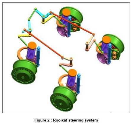
Thanks Matt and Dennis.
Florida, United States
Joined: May 16, 2002
KitMaker: 17,694 posts
Armorama: 13,742 posts
Posted: Saturday, December 03, 2016 - 05:33 AM UTC
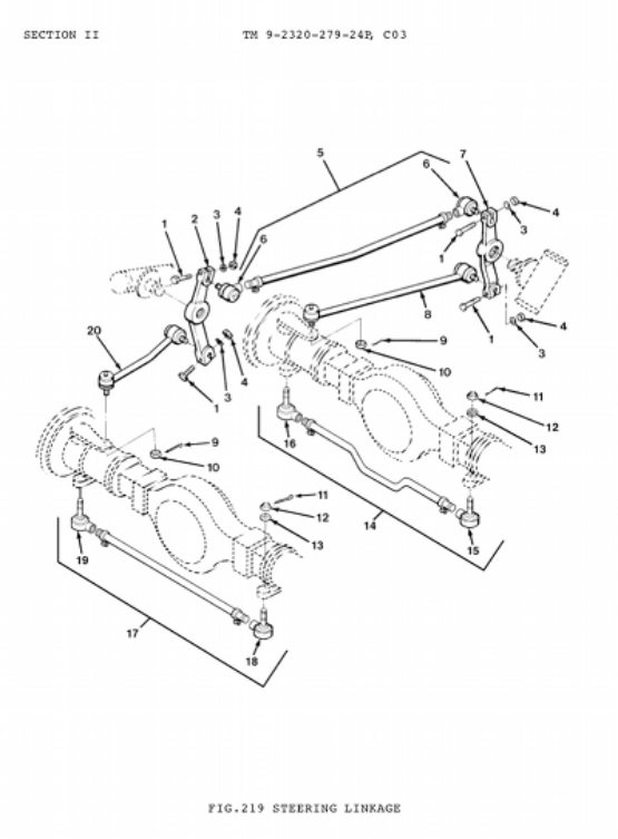
As a note, the above steering pattern is for HEMTT A4 versions which have TAK4 front suspensions. A1 and A2 HEMTTs use a standard steering system with two steering boxes and steering arms on the left side of the frame. The below pic was shows earlier in this thread. The front of the vehicle is to the right.
Field Artillery --- The KING of BATTLE!!!
"People sleep peaceably in their beds at night only because rough men stand ready to do violence on their behalf." -- George Orwell
Showcase
#521
Kentucky, United States
Joined: April 13, 2011
KitMaker: 9,465 posts
Armorama: 8,695 posts
Posted: Saturday, December 03, 2016 - 06:03 AM UTC
Gino - I was only referring to the angle of the wheels after all the other toe-in discussion.
Florida, United States
Joined: May 16, 2002
KitMaker: 17,694 posts
Armorama: 13,742 posts
Posted: Saturday, December 03, 2016 - 06:44 PM UTC
Ah, OK. I was a little confused and thought others might be too. Just wanted to clarify.
Field Artillery --- The KING of BATTLE!!!
"People sleep peaceably in their beds at night only because rough men stand ready to do violence on their behalf." -- George Orwell
Showcase
#521
Kentucky, United States
Joined: April 13, 2011
KitMaker: 9,465 posts
Armorama: 8,695 posts
Posted: Saturday, December 10, 2016 - 12:21 AM UTC
#521
Kentucky, United States
Joined: April 13, 2011
KitMaker: 9,465 posts
Armorama: 8,695 posts
Posted: Monday, December 19, 2016 - 10:59 PM UTC
 Season's Greetings
Nova Scotia, Canada
Joined: February 23, 2006
KitMaker: 9 posts
Armorama: 9 posts
Posted: Tuesday, January 03, 2017 - 09:21 PM UTC
#521
Kentucky, United States
Joined: April 13, 2011
KitMaker: 9,465 posts
Armorama: 8,695 posts
Posted: Tuesday, January 03, 2017 - 11:18 PM UTC
If you are talking about the two drawings back on page 18 I totally agree they are confusing. You must superimpose the two drawings over each other to see the entire system.
One represents the parking brake system and the other, the service brakes.
Remember Dustin said these large rear brake cans are actually double acting cans that contain both the parking brake and the service brake actuators in the same can. So both hoses run from each brake can to the equalizer valves for a total of four hoses per valve. Then there are two feeder hoses per valve; one for the service brakes and one for the parking brakes. Therefore a total six hoses per valve.
F.Y.I. on my HEMTT, at this point, the two feeder air hoses to each valve HAVE NOT yet been modeled.
Upon starting the engine (and therefore the air pump) the first thing that happens is the service brake system gets charged with air and this allows the service brakes to function. After that the parking brake system gets charged with air and only then does this release the parking brakes.*
I am sure someone else may have a better way to express all this.
*The parking brakes are normally held "ON" using a spring and are released only when that part of the actuator can gets charged with air. Any loss of air in an emergency causes these brakes to be applied.
The service brakes are normally "OFF" and only get applied when air is sent from the brake peddle air control valve to the other side of the brake actuator can.
Nova Scotia, Canada
Joined: February 23, 2006
KitMaker: 9 posts
Armorama: 9 posts
Posted: Wednesday, January 04, 2017 - 12:24 AM UTC
Nova Scotia, Canada
Joined: February 23, 2006
KitMaker: 9 posts
Armorama: 9 posts
Posted: Wednesday, January 04, 2017 - 12:37 AM UTC
this picture is what I'm talking about that's confusing it shows just 2 lines from left rear brake can going to the valve and the other lines from the right can going to the valve on the other side of the cross member
http://data.primeportal.net/m983/165271788ByZPBB_fs.jpg#521
Kentucky, United States
Joined: April 13, 2011
KitMaker: 9,465 posts
Armorama: 8,695 posts
Posted: Wednesday, January 04, 2017 - 01:27 AM UTC
One feeder line goes to one air tank and the other goes to another. The tank for the service brake system fills up first then the parking brake tank. Between these two tanks there is a resister valve set for about 27psi. This valve guarentees that the service tank fills up first and then the parking brake tank.
Nova Scotia, Canada
Joined: February 23, 2006
KitMaker: 9 posts
Armorama: 9 posts
Posted: Friday, January 13, 2017 - 12:55 AM UTC
#521
Kentucky, United States
Joined: April 13, 2011
KitMaker: 9,465 posts
Armorama: 8,695 posts
Posted: Saturday, January 14, 2017 - 08:12 AM UTC
Here are the schematics for the steering hydraulics. I have not found anything (yet) on the routing of the piping to the air reserve tanks.


#521
Kentucky, United States
Joined: April 13, 2011
KitMaker: 9,465 posts
Armorama: 8,695 posts
Posted: Saturday, January 14, 2017 - 09:33 AM UTC
And here is the air tank info:


Nova Scotia, Canada
Joined: February 23, 2006
KitMaker: 9 posts
Armorama: 9 posts
Posted: Monday, January 16, 2017 - 12:01 AM UTC
Nova Scotia, Canada
Joined: February 23, 2006
KitMaker: 9 posts
Armorama: 9 posts
Posted: Friday, January 27, 2017 - 05:54 AM UTC
you would happen to have any pics of the electrical cables running from brake lights and so on ?
#521
Kentucky, United States
Joined: April 13, 2011
KitMaker: 9,465 posts
Armorama: 8,695 posts
Posted: Thursday, February 09, 2017 - 03:57 AM UTC
Taillight wiring:

#521
Kentucky, United States
Joined: April 13, 2011
KitMaker: 9,465 posts
Armorama: 8,695 posts
Posted: Thursday, February 09, 2017 - 04:01 AM UTC
This is how I handled the taillight wiring:

#521
Kentucky, United States
Joined: April 13, 2011
KitMaker: 9,465 posts
Armorama: 8,695 posts
Posted: Thursday, February 09, 2017 - 04:14 AM UTC
Still a few details to finish before the HEMTT's first hobby competition on the 18th:


Florida, United States
Joined: May 16, 2002
KitMaker: 17,694 posts
Armorama: 13,742 posts
Posted: Thursday, February 09, 2017 - 07:30 AM UTC
It looks really good. Nice weathering and paint finish. Have you decided on a load for it?
Field Artillery --- The KING of BATTLE!!!
"People sleep peaceably in their beds at night only because rough men stand ready to do violence on their behalf." -- George Orwell
Showcase
#521
Kentucky, United States
Joined: April 13, 2011
KitMaker: 9,465 posts
Armorama: 8,695 posts
Posted: Thursday, February 09, 2017 - 09:10 AM UTC
Not yet. For now I am going to display it with the LHS and empty flat rack partially up in the air. (Was kind of waiting for your inspiration on that score.)
Tennessee, United States
Joined: January 10, 2005
KitMaker: 337 posts
Armorama: 332 posts
Posted: Friday, February 10, 2017 - 01:20 AM UTC
Me likey! Good luck at the Comps!
In Memory of Cpl. Cecil T. Nicholson, U.S. Army, 1931-2006