Hosted by Darren Baker
MiniArt Grant w/interior build log interest?
GaryKato

Joined: December 06, 2004
KitMaker: 3,694 posts
Armorama: 2,693 posts

Posted: Monday, January 27, 2020 - 05:29 PM UTC
This thread has a LOT of good model building techniques! Thanks!

PRH001

Joined: June 16, 2014
KitMaker: 681 posts
Armorama: 603 posts

Posted: Tuesday, January 28, 2020 - 07:23 AM UTC
Glad youíre finding this log useful!

PRH001

Joined: June 16, 2014
KitMaker: 681 posts
Armorama: 603 posts

Posted: Sunday, February 02, 2020 - 02:10 PM UTC
Here is a look at the way I was most comfortable assembling the track runs on the Grant. Itís not rocket science, but it allows me to keep my sanity during this process.
Here Iím beginning the install by lifting both of the wedge/link connectors to allow the outer portion of the next link to be slid close to the previously completed link.

When the outer portion is in place, the wedge/ link connectors are pivoted down into the recesses in the track pad piece.

Next, I place a wedge/link connector into the next position furthest away from me. The shape is awkward, so they fall out of place very easily.

Next I place Tamiya Extra Thin cement into the center recess of the track pad.
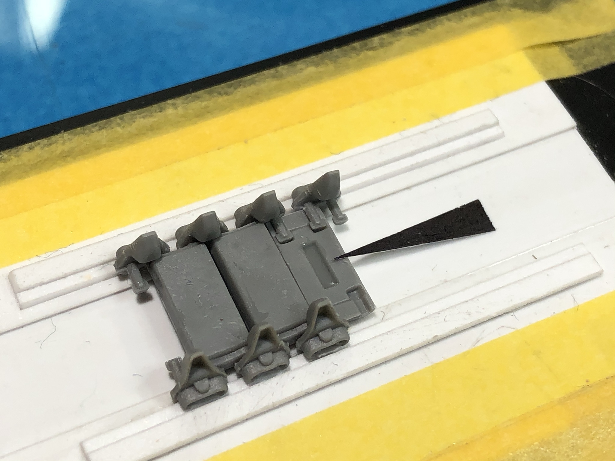
I then place the inner portion of the track pad loosely in place.
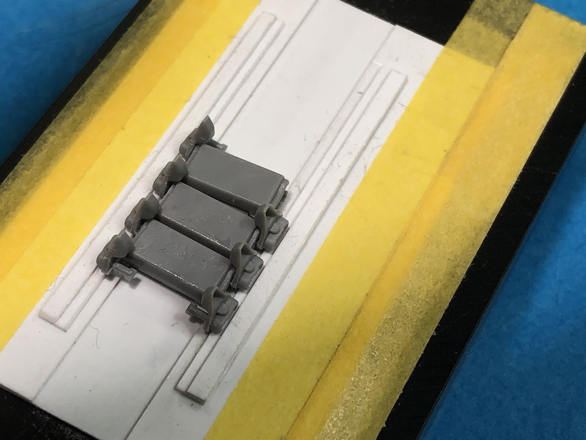
Next I slide the remaining wedge/link connector into the hole.
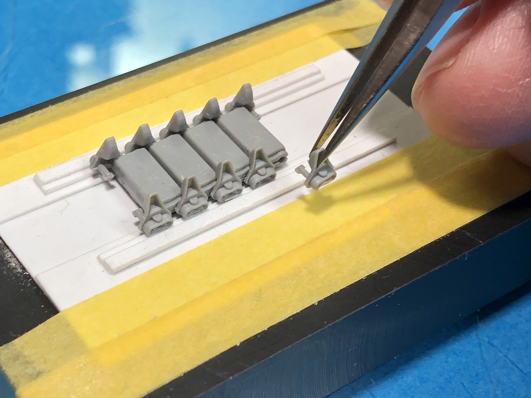

Once itís seated all of the way, I push the two track pad halves together.
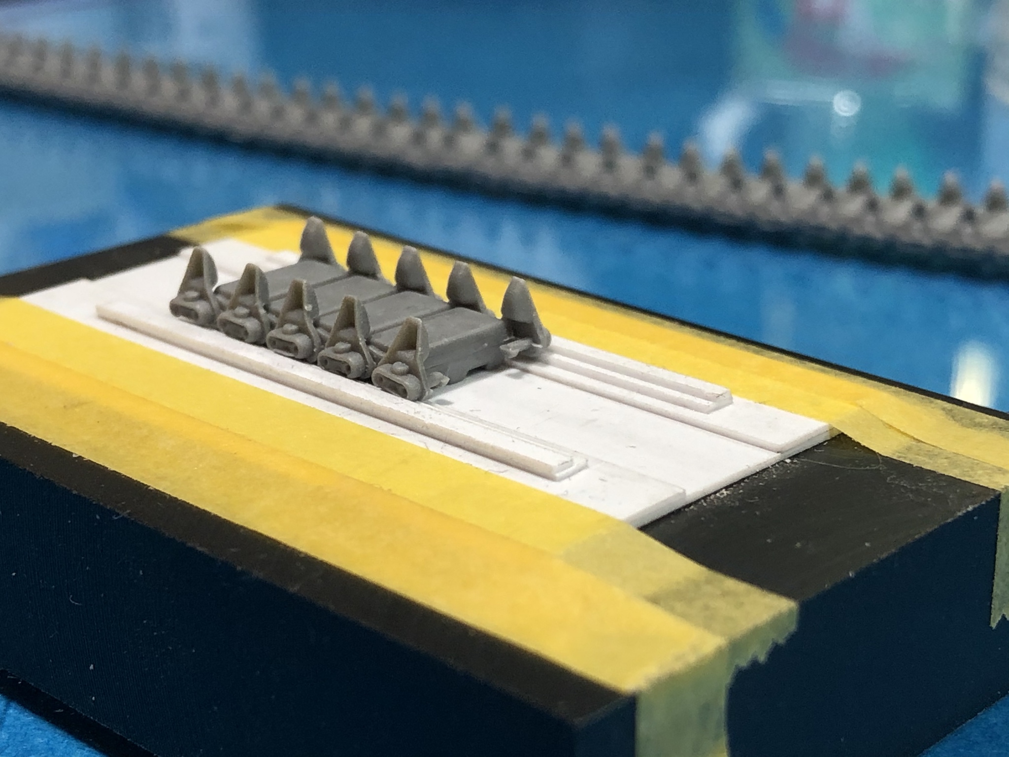
A small amount of the Tamiya Extra Thin is applied to the front and back joints to seal the track pad and the process repeats.
A note about this is that I tried placing all of the wedge/link connector parts in place but they were just not stable enough to allow placement of the innermost part of the track pad...
I build runs of ten links, and then join them to the main run. This allows me to focus on construction versus counting and remembering link numbers.
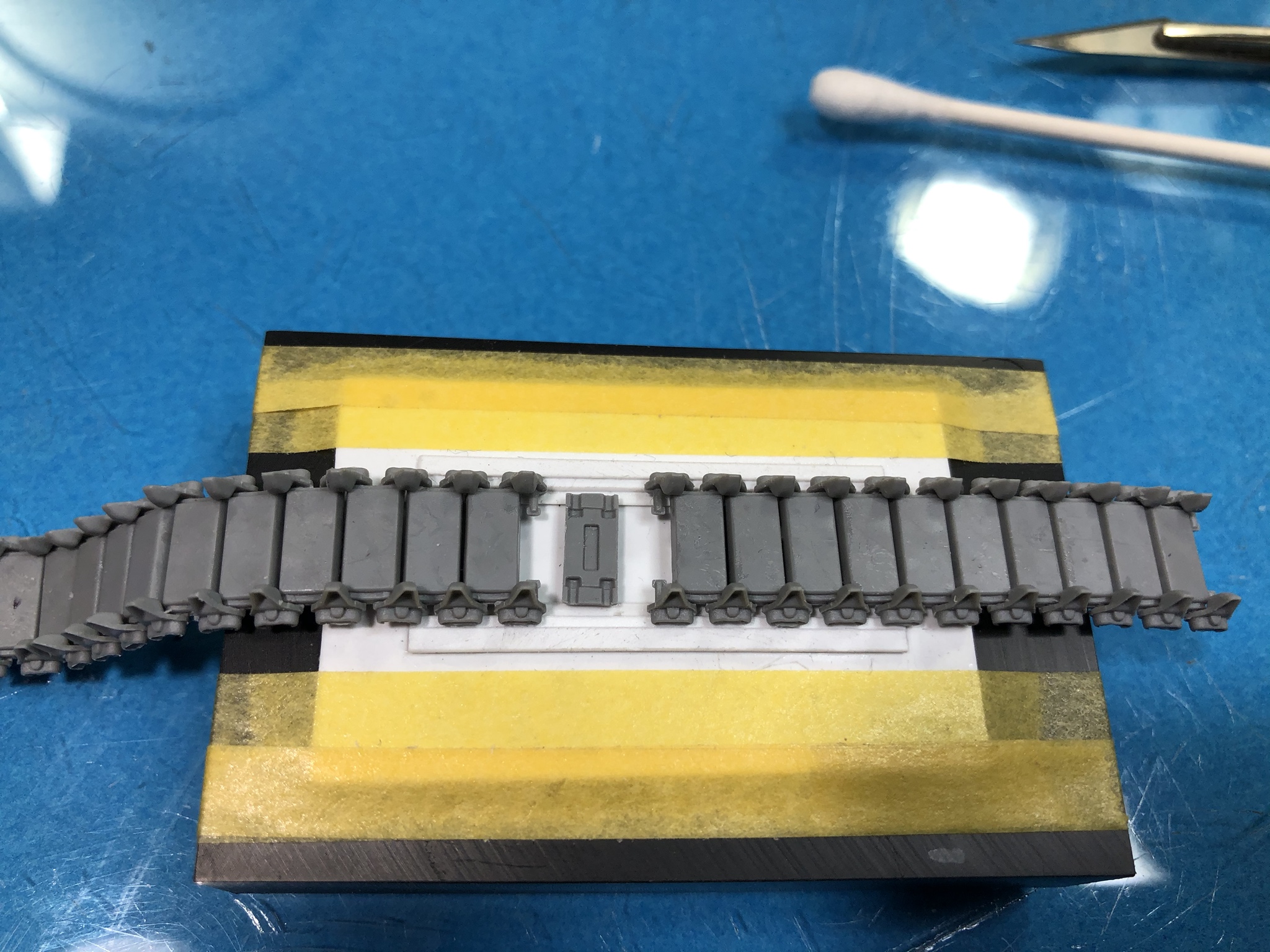
The recess in the outer pad half gets some cement and the inner pad half is installed. The dot shows the connecting part so that I can keep track of run length.

Iím currently about 3/4 of the way done assembling the tracks, with the first full track run taking about 3 to 4 hours to complete. Care and repeatable processes are the key.
Hope this helps someone.
Cheers all!
Here Iím beginning the install by lifting both of the wedge/link connectors to allow the outer portion of the next link to be slid close to the previously completed link.

When the outer portion is in place, the wedge/ link connectors are pivoted down into the recesses in the track pad piece.

Next, I place a wedge/link connector into the next position furthest away from me. The shape is awkward, so they fall out of place very easily.

Next I place Tamiya Extra Thin cement into the center recess of the track pad.

I then place the inner portion of the track pad loosely in place.

Next I slide the remaining wedge/link connector into the hole.


Once itís seated all of the way, I push the two track pad halves together.

A small amount of the Tamiya Extra Thin is applied to the front and back joints to seal the track pad and the process repeats.
A note about this is that I tried placing all of the wedge/link connector parts in place but they were just not stable enough to allow placement of the innermost part of the track pad...
I build runs of ten links, and then join them to the main run. This allows me to focus on construction versus counting and remembering link numbers.

The recess in the outer pad half gets some cement and the inner pad half is installed. The dot shows the connecting part so that I can keep track of run length.

Iím currently about 3/4 of the way done assembling the tracks, with the first full track run taking about 3 to 4 hours to complete. Care and repeatable processes are the key.
Hope this helps someone.
Cheers all!

PRH001

Joined: June 16, 2014
KitMaker: 681 posts
Armorama: 603 posts

Posted: Wednesday, February 05, 2020 - 01:55 PM UTC
Iím happy to say Iíve completed the the basic assembly of the Grant track runs. Care when cleaning, placing and cementing are essential.

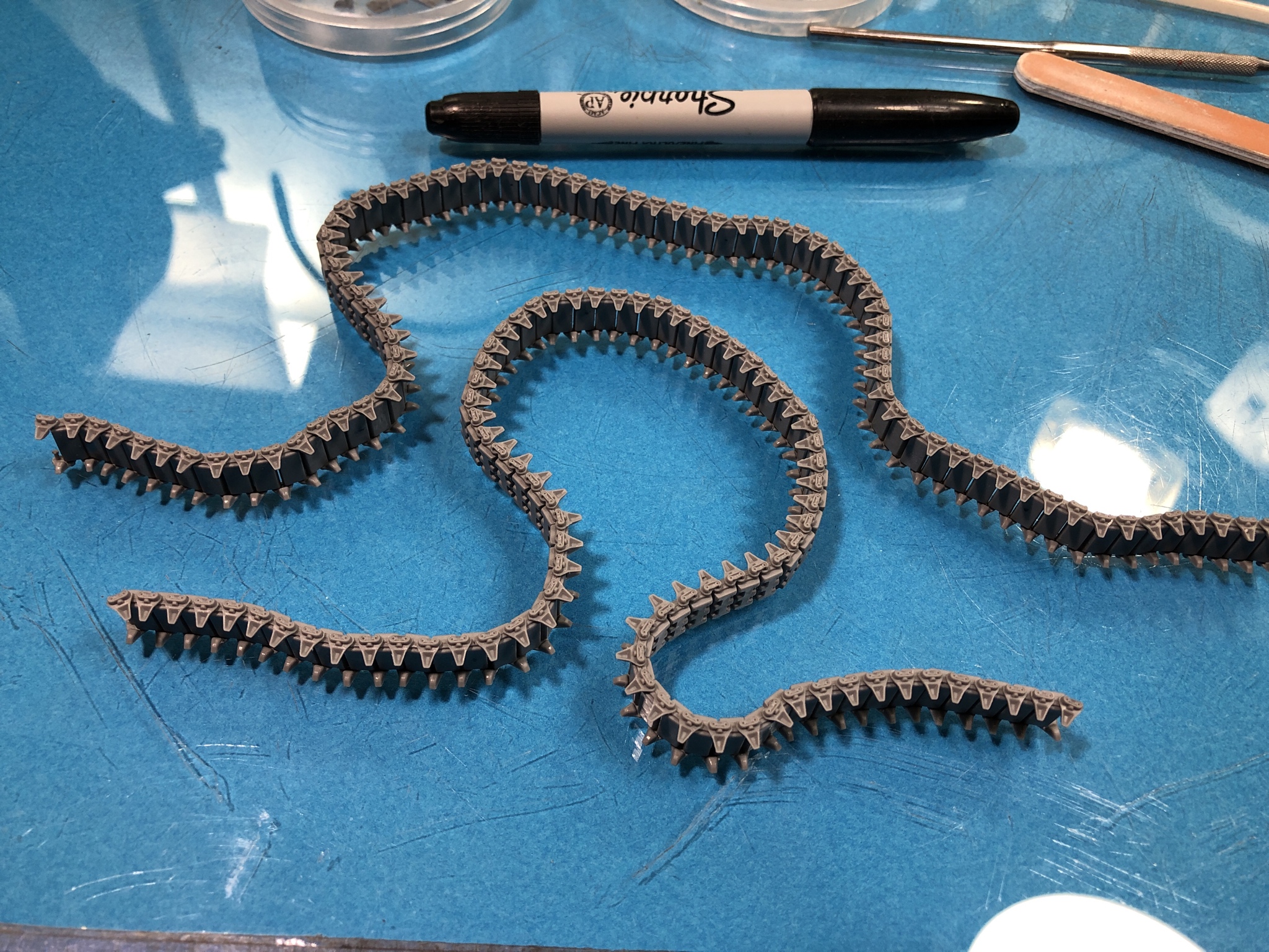
They have been set aside for the cement to cure before painting and installation.


They have been set aside for the cement to cure before painting and installation.

Dioramartin

Joined: May 04, 2016
KitMaker: 1,476 posts
Armorama: 1,463 posts

Posted: Wednesday, February 05, 2020 - 04:00 PM UTC
Hey Paul I've only just checked this log out (not on my usual radar) & just wanted to say the Grant, photos & log add up to a work of art in the making, arguably even better than Old Warlokeís Mk IV just completed. I spent a totally absorbing 20 minutes here - thanks, bravo, itís a beauty 


PRH001

Joined: June 16, 2014
KitMaker: 681 posts
Armorama: 603 posts

Posted: Thursday, February 06, 2020 - 01:09 AM UTC
I appreciate the kind words. Hopefully the end product will look the part and someone will benefit from my observations.
Cheers
Paul H
Cheers
Paul H
Track_Slap

Joined: February 08, 2020
KitMaker: 3 posts
Armorama: 3 posts

Posted: Friday, February 07, 2020 - 02:21 PM UTC
Paul, Thankyou for this blog. It's fantastic.
Not long ago I purchased the Miniart M3 Lee. Was nearly ready to start when Miniart released the Australian M3 Lee. Had to buy that too! My Grandfather was a driver in the 2nd Aust Tank Btn.
I found your blog when looking for interior colour schemes. High standard for mortals to work to! Great information though.

KoSprueOne

Joined: March 05, 2004
KitMaker: 4,011 posts
Armorama: 1,498 posts

Posted: Friday, February 07, 2020 - 04:10 PM UTC
Nice work on them tracks.


PRH001

Joined: June 16, 2014
KitMaker: 681 posts
Armorama: 603 posts

Posted: Friday, February 07, 2020 - 05:15 PM UTC
Quoted Text
Not long ago I purchased the Miniart M3 Lee. Was nearly ready to start when Miniart released the Australian M3 Lee. Had to buy that too! My Grandfather was a driver in the 2nd Aust Tank Btn.
Peter, I canít think of a better reason to tackle an M3 Lee! I really hope there is something in this log youíll find useful for your build.
Good luck!

PRH001

Joined: June 16, 2014
KitMaker: 681 posts
Armorama: 603 posts

Posted: Friday, February 07, 2020 - 05:22 PM UTC
Quoted Text
Nice work on them tracks.
Thanks! Glad to have the basic track assembly step behind me...

PRH001

Joined: June 16, 2014
KitMaker: 681 posts
Armorama: 603 posts

Posted: Sunday, February 09, 2020 - 02:44 PM UTC
This weekís progress on the Grant.
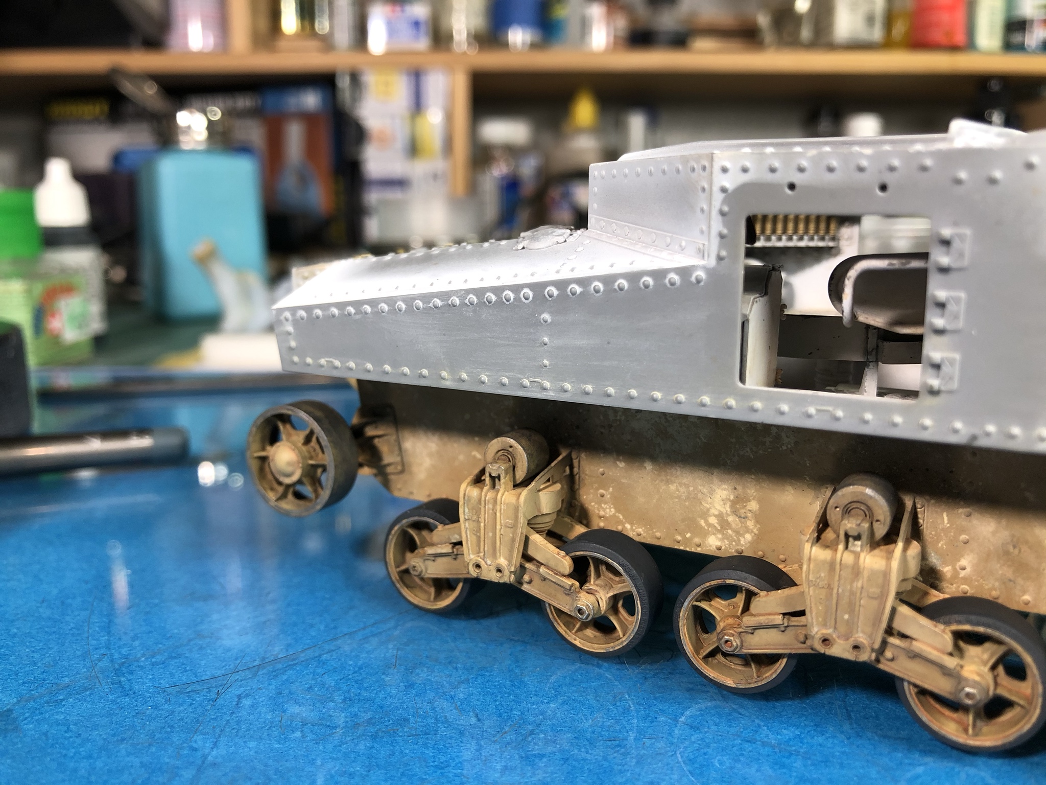
I mixed up an oil paint wash from 502 Abteilung Wash Brown and Sand Brown for German Armor and applied it to the detail areas on the hull sides. The color did not turn out as Iíd hoped, but I decided to work with it.

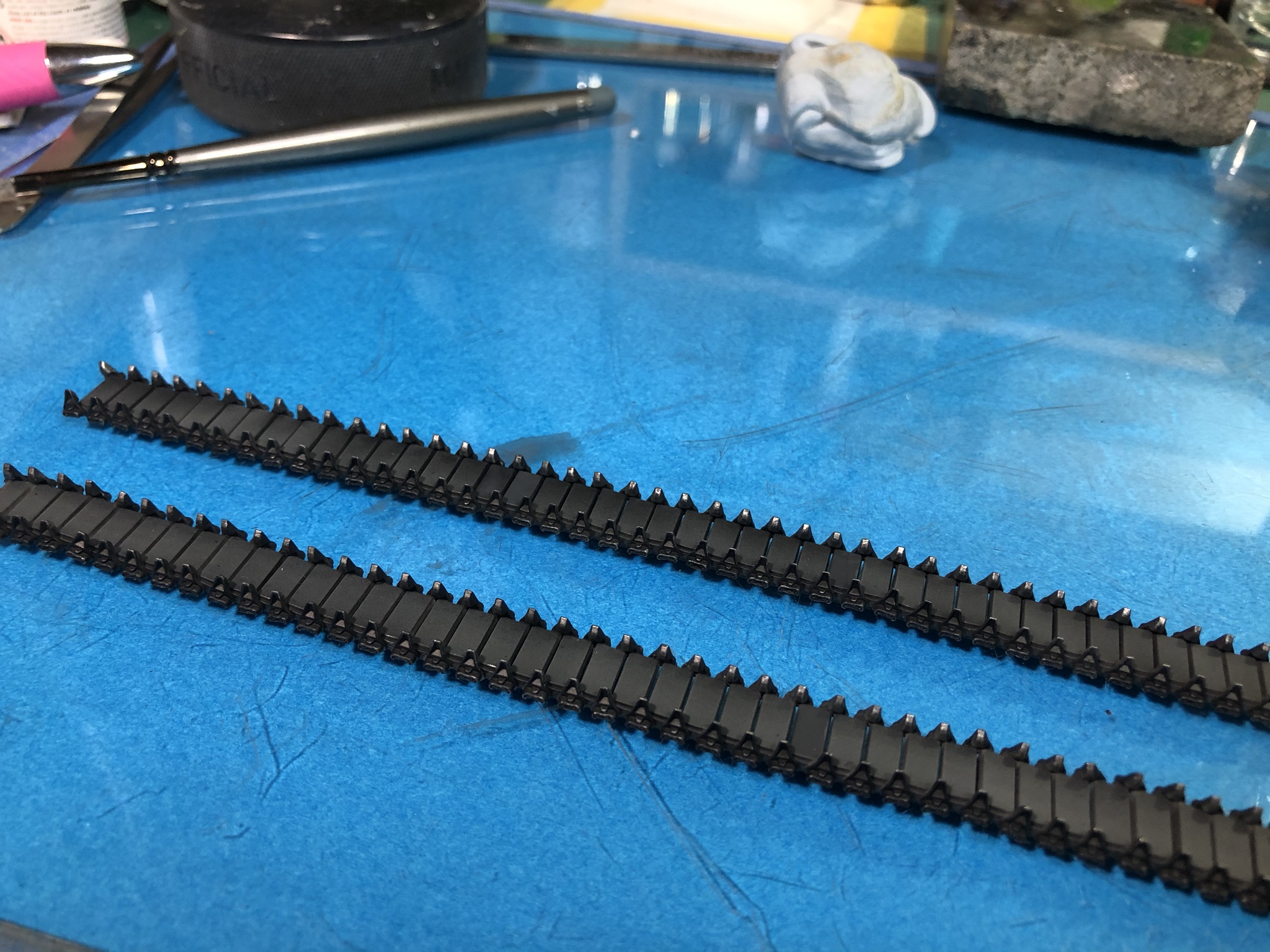
It was time to prime/paint the tracks for installation, so I laid the runs out and sprayed them with Badger Stynylrez Black Primer. I draped the runs over a rod to enable me to get coverage in between the track links and on the sides.

While the track runs were drying, I randomly applied pigments from Ammo of Mig and touched certain places with Pigment Fixer to get the random weathering I prefer. The colors used were Sand, Rubble, and North Africa Dust.
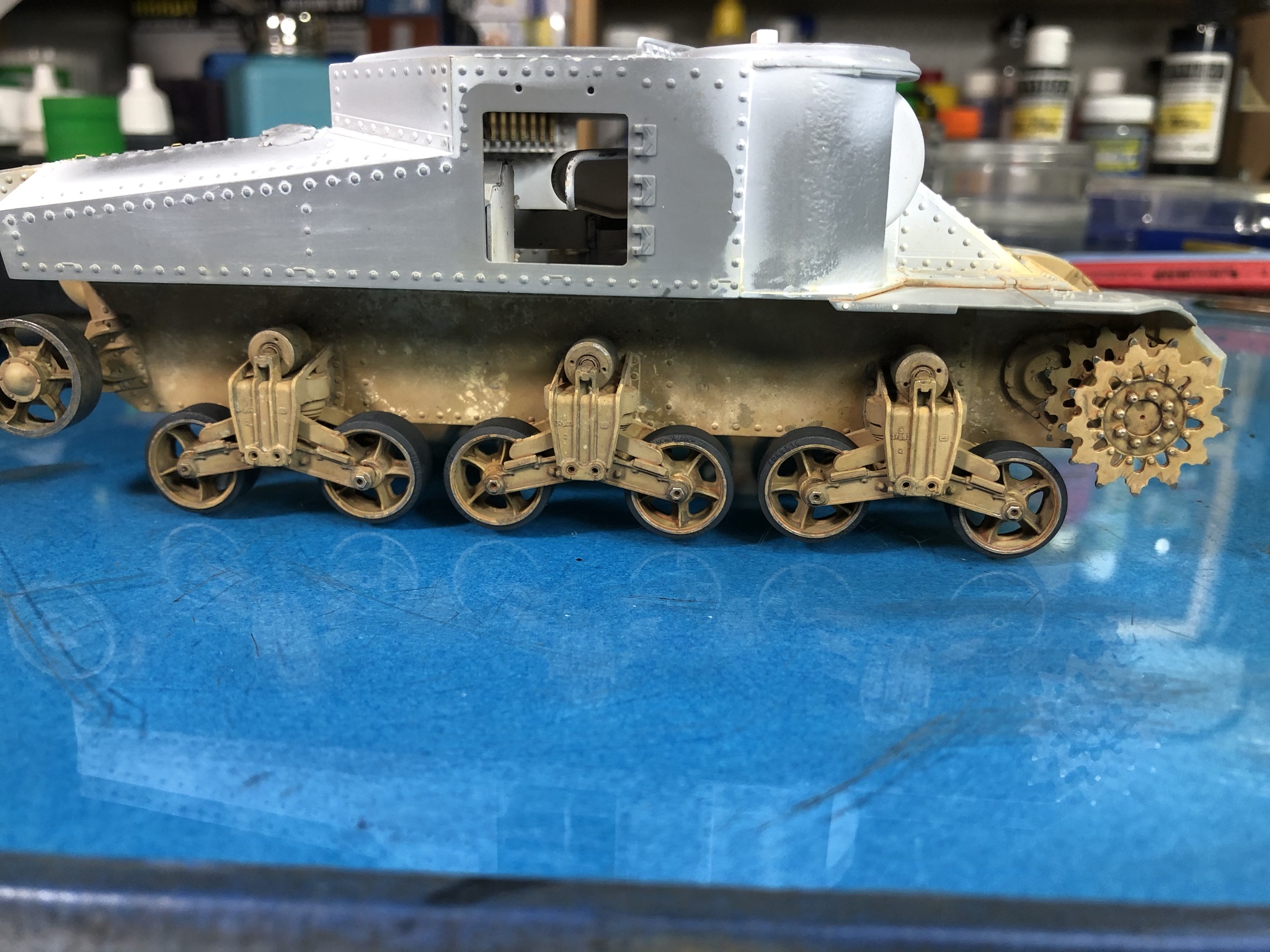
I also drybrushed Vallejo Dark Aluminumí onto the outer edges of the road wheels and on the tips of the drive sprockets. The idler wheels were roughly drybrushed at the same time.
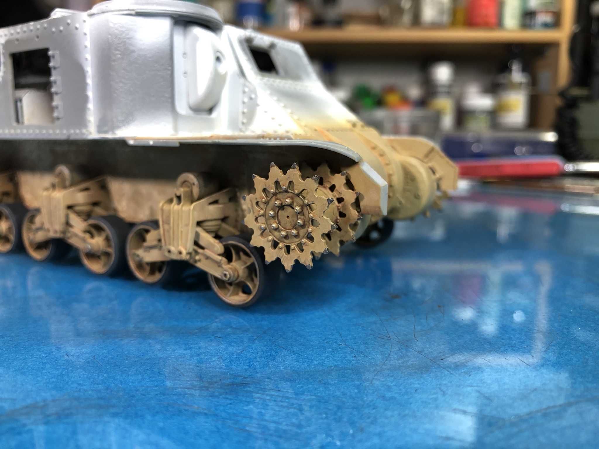

I misted a random coat of Tamiya Buff over the track runs and roughly drybrushed Vallejo Dark Aluminum onto the guide horns.

Moving on to the track run install, I decided that I wanted to fit the last link without trimming, so I used the old tie the track ends together trick to allow the installation of the last link. The thread used is .0005 thick invisible thread.
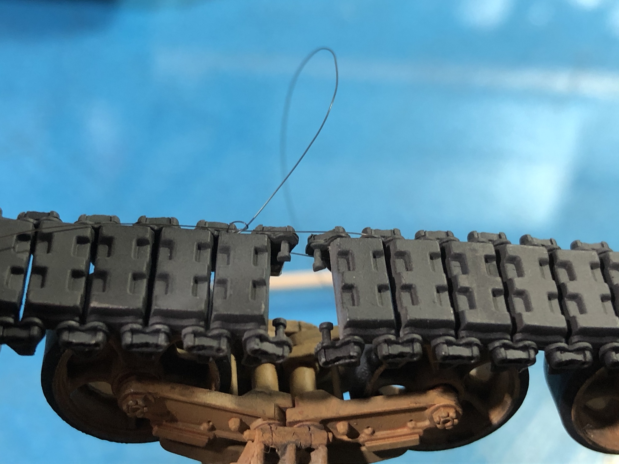
The outer link piece is put in place and the connecting links for one side are positioned in their cutouts and cemented using Tamiyaís Extra Thin cement.

Once that had set I put cement in the center cutout like I did when assembling the track runs and I set the inner pad piece in place.

The link was then painted to match the rest of the track run.


There are lots of ways to accomplish this process, but this is how I decided to tackle the job. The plan is for this area to be covered up while I press forward with the build. Bottom line, the initial weathering and installation of the tracks is behind me.
Cheers!

I mixed up an oil paint wash from 502 Abteilung Wash Brown and Sand Brown for German Armor and applied it to the detail areas on the hull sides. The color did not turn out as Iíd hoped, but I decided to work with it.

It was time to prime/paint the tracks for installation, so I laid the runs out and sprayed them with Badger Stynylrez Black Primer. I draped the runs over a rod to enable me to get coverage in between the track links and on the sides.

While the track runs were drying, I randomly applied pigments from Ammo of Mig and touched certain places with Pigment Fixer to get the random weathering I prefer. The colors used were Sand, Rubble, and North Africa Dust.

I also drybrushed Vallejo Dark Aluminumí onto the outer edges of the road wheels and on the tips of the drive sprockets. The idler wheels were roughly drybrushed at the same time.


I misted a random coat of Tamiya Buff over the track runs and roughly drybrushed Vallejo Dark Aluminum onto the guide horns.


Moving on to the track run install, I decided that I wanted to fit the last link without trimming, so I used the old tie the track ends together trick to allow the installation of the last link. The thread used is .0005 thick invisible thread.

The outer link piece is put in place and the connecting links for one side are positioned in their cutouts and cemented using Tamiyaís Extra Thin cement.

Once that had set I put cement in the center cutout like I did when assembling the track runs and I set the inner pad piece in place.

The link was then painted to match the rest of the track run.


There are lots of ways to accomplish this process, but this is how I decided to tackle the job. The plan is for this area to be covered up while I press forward with the build. Bottom line, the initial weathering and installation of the tracks is behind me.
Cheers!

Dioramartin

Joined: May 04, 2016
KitMaker: 1,476 posts
Armorama: 1,463 posts

Posted: Sunday, February 09, 2020 - 09:55 PM UTC
Yowza apart from the slick track fix Iím really impressed by the weathering on the bogies & hull plates Ė from what Iíd call scale-distance the random colour variations look perfect/superb. In ultra close-up maybe the rusty shade needs moderating but overall exceptional - if you can keep that standard up thisíll be a prize-winner in any show. (PS others will know better than I, but is there an argument that the rubber wheels need some wear/pitting?) 


PRH001

Joined: June 16, 2014
KitMaker: 681 posts
Armorama: 603 posts

Posted: Monday, February 10, 2020 - 01:42 AM UTC
I considered simulating wear with pitting and chunking on both the wheels and the track pads, but I i was leaning towards a pretty fresh to the fray build. The tracks on the Grant certainly did chunk in desert conditions, but this took a while. As for the wheels, based on the photos Iíve seen, those seem to have a tendency to wear more smoothly.
Again, I donít disagree with your idea, I just chose to do a newer tank and the weathering to follow should hopefully reflect that.
Thanks for the helpful feedback!
Again, I donít disagree with your idea, I just chose to do a newer tank and the weathering to follow should hopefully reflect that.
Thanks for the helpful feedback!

PRH001

Joined: June 16, 2014
KitMaker: 681 posts
Armorama: 603 posts

Posted: Tuesday, February 11, 2020 - 02:52 PM UTC
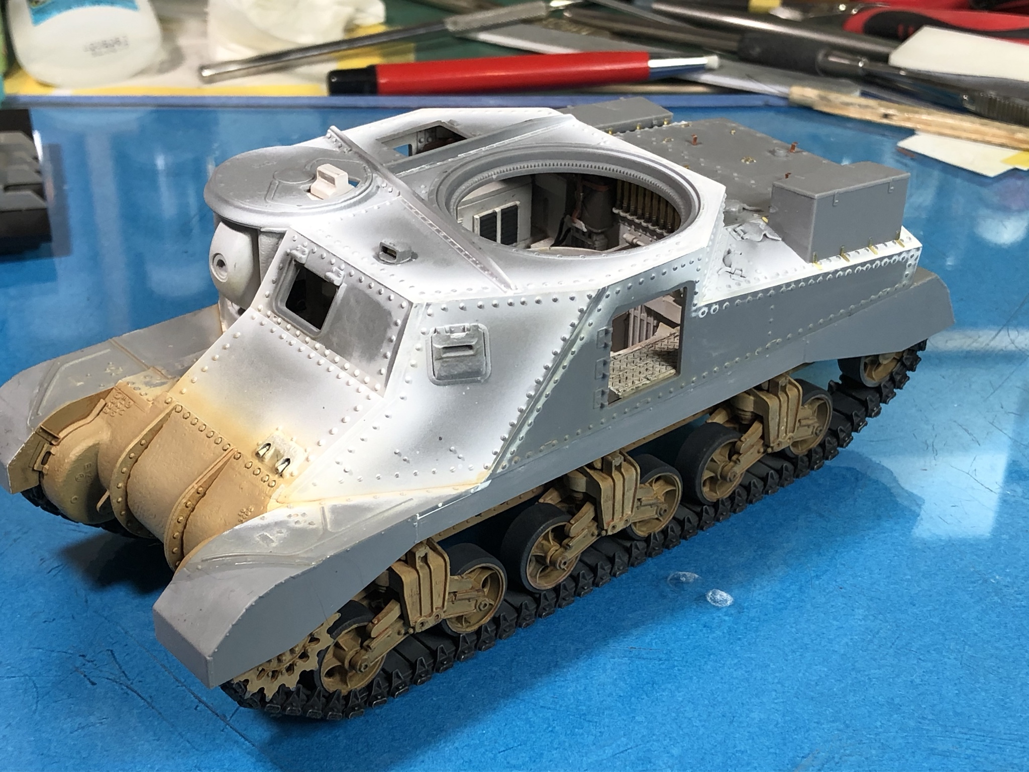
Had a snow day today, so I took the opportunity to make a bit of progress on the Grant. First up, I test fit the sand skirts and found the left one had a substantial gap where it attaches to the hull. Checking ahead in the instructions, I didnít see anything that would cause this to be needed, so I cut a piece of styrene, filled the gap and faired the addition into the shield.

Here is the area once installation was completed.

I pressed on with the install of both sides and here are a few pictures of the skirts once fitted.

Next up was the assembly and installation of the storage boxes on the rear sides. The instructions show building the boxes and installing the photo-etched brackets before placing the boxes on the model, but that seemed to be asking for trouble. Instead, I cemented the main box assemblies in place and then attached the PE brackets. Iím very glad I did, as the brackets only fit one way. Notice there is one side of the piece thatís shorter and this is the side that attaches to the box.
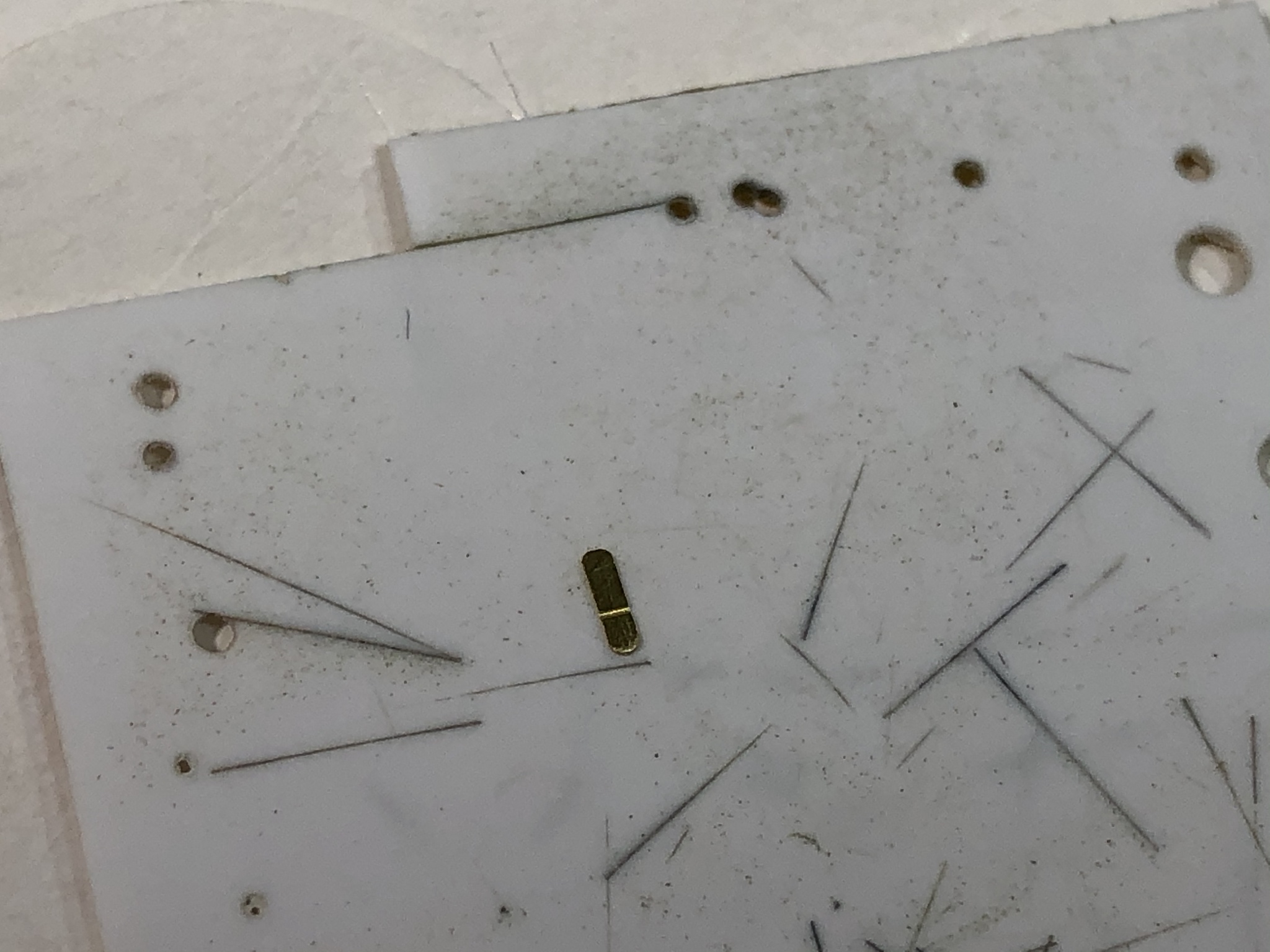
I pre-bent the parts to an approximate angle and then test fit.

When placed, I used a chisel to complete the bend in place.

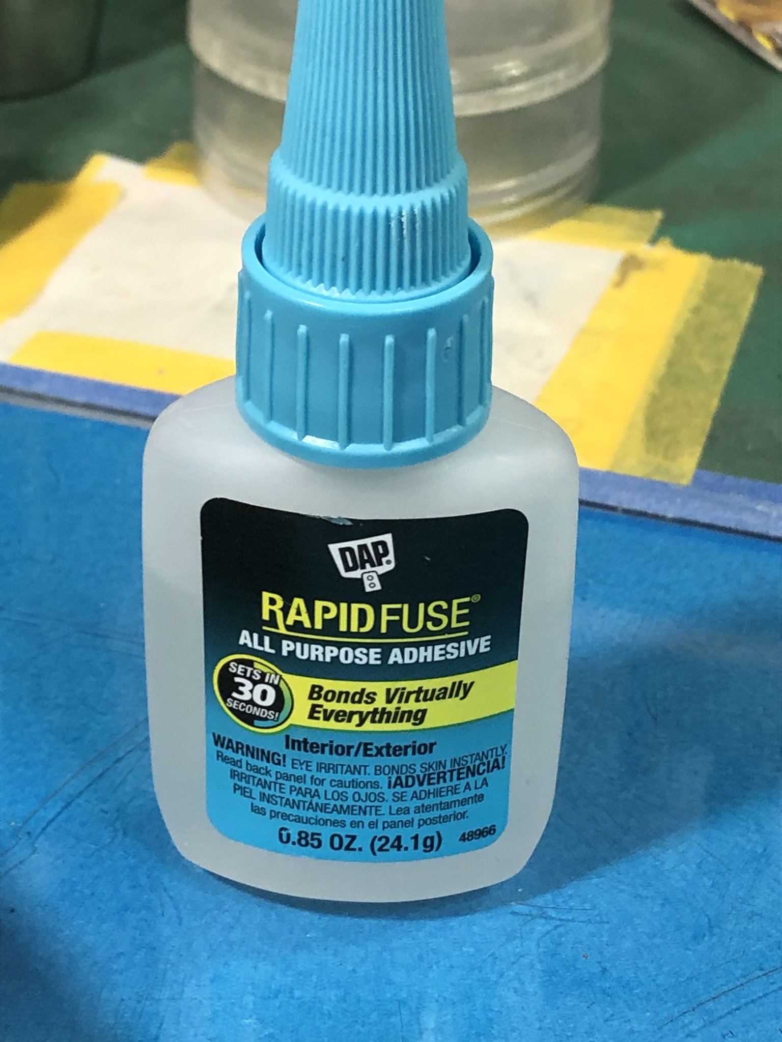
The part was removed and I used DAP Rapidfuse to attach the parts. I saw this on Paul Budzikís website and he was correct, I works beautifully.
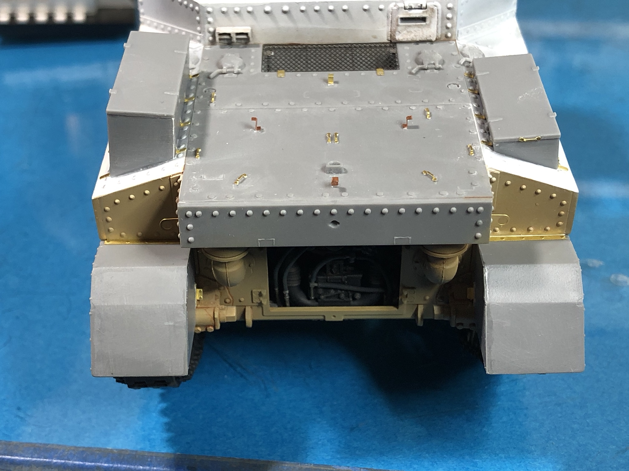
Hereís todayís overall progress.



Hope this saves someone some headaches...

Here is the area once installation was completed.

I pressed on with the install of both sides and here are a few pictures of the skirts once fitted.


Next up was the assembly and installation of the storage boxes on the rear sides. The instructions show building the boxes and installing the photo-etched brackets before placing the boxes on the model, but that seemed to be asking for trouble. Instead, I cemented the main box assemblies in place and then attached the PE brackets. Iím very glad I did, as the brackets only fit one way. Notice there is one side of the piece thatís shorter and this is the side that attaches to the box.

I pre-bent the parts to an approximate angle and then test fit.

When placed, I used a chisel to complete the bend in place.

The part was removed and I used DAP Rapidfuse to attach the parts. I saw this on Paul Budzikís website and he was correct, I works beautifully.

Hereís todayís overall progress.


Hope this saves someone some headaches...

PRH001

Joined: June 16, 2014
KitMaker: 681 posts
Armorama: 603 posts

Posted: Wednesday, February 12, 2020 - 03:52 AM UTC
As an additional heads up for those looking to build a specific Grant Mk I, the interior kit which this build log covers only comes with the squared-off factory style sand skirts.
If you want to build the version that has the more rounded style fit by the in-theater shops, those are available in Miniartís non-interior version of the Grant.
The Takom release has the factory style squared-off style sand skirts.
This may have been discussed elsewhere, but I havenít seen it, so I thought Iíd mention it since I just Installed those items on my build.

PRH001

Joined: June 16, 2014
KitMaker: 681 posts
Armorama: 603 posts

Posted: Sunday, February 16, 2020 - 03:33 PM UTC
Today was the day for small detail items. First up, I folded and soldered the brackets for the tripod.
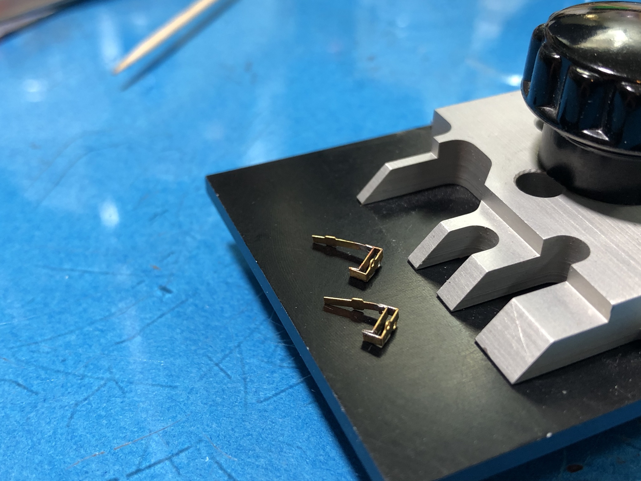
While the soldering gear was out I went ahead and took care of the basket for the right side fender.
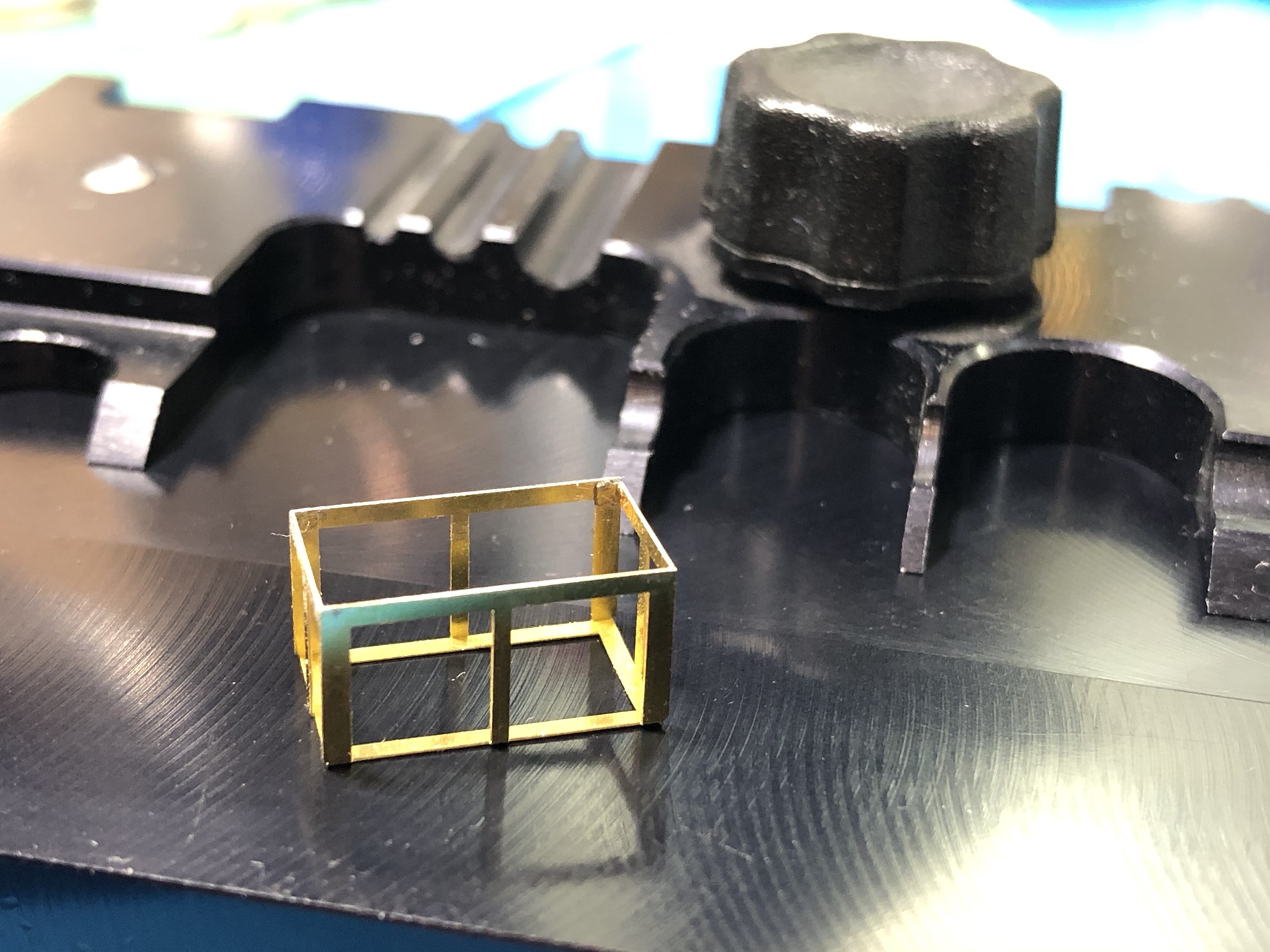

The brackets are installed using CA glue. I just have pretty much reached the conclusion that I donít gain anything by attaching sheet styrene to the PE and then placing with standard cement. The parts stick up higher and are easier to knock off.

I wired and installed the light assembly on the left side and the bent and installed the guard.
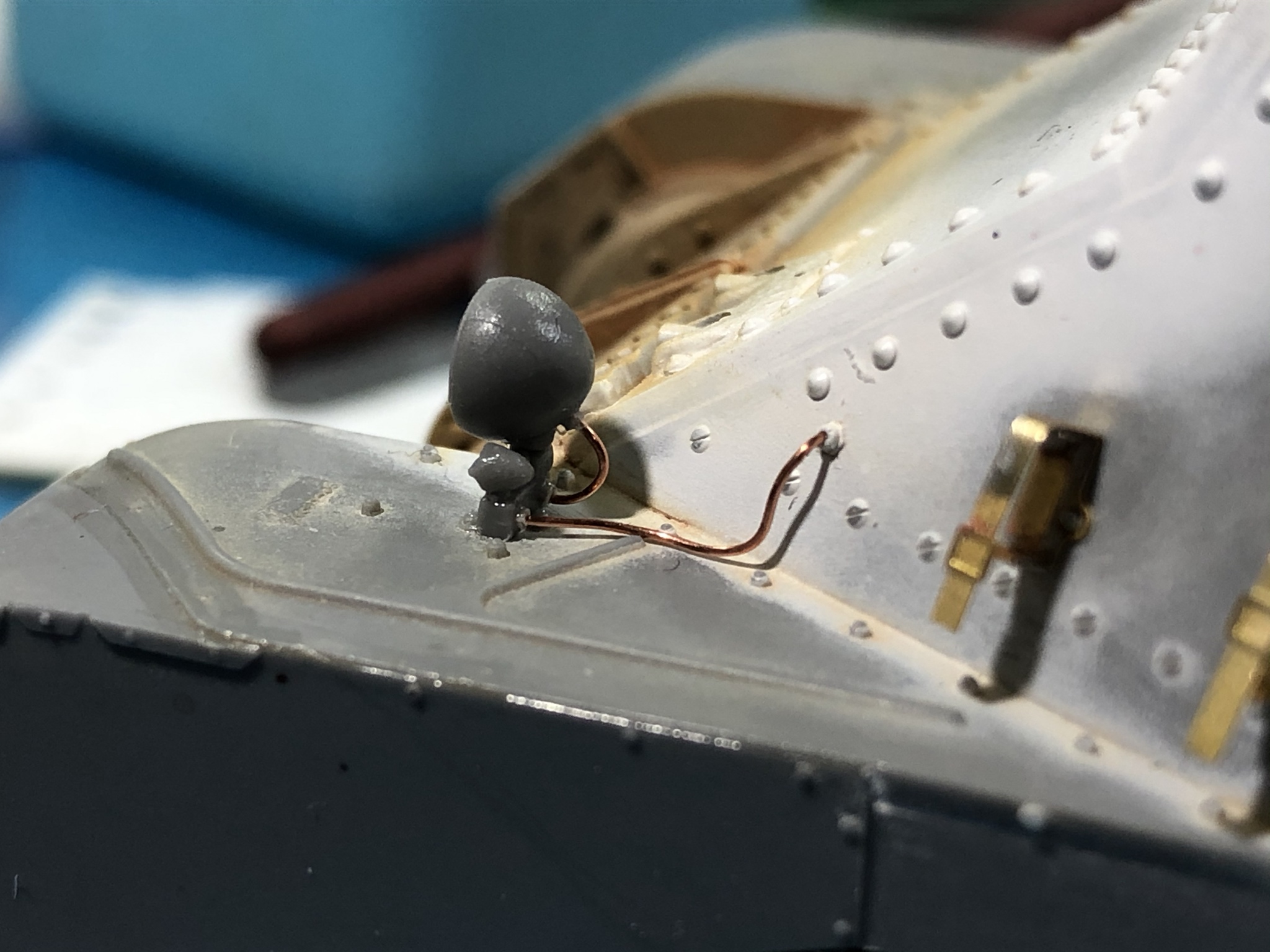

I did the cleanup and wiring on the right side. I installed the fender support and completely reworked the siren do to a huge amount of mold offset.
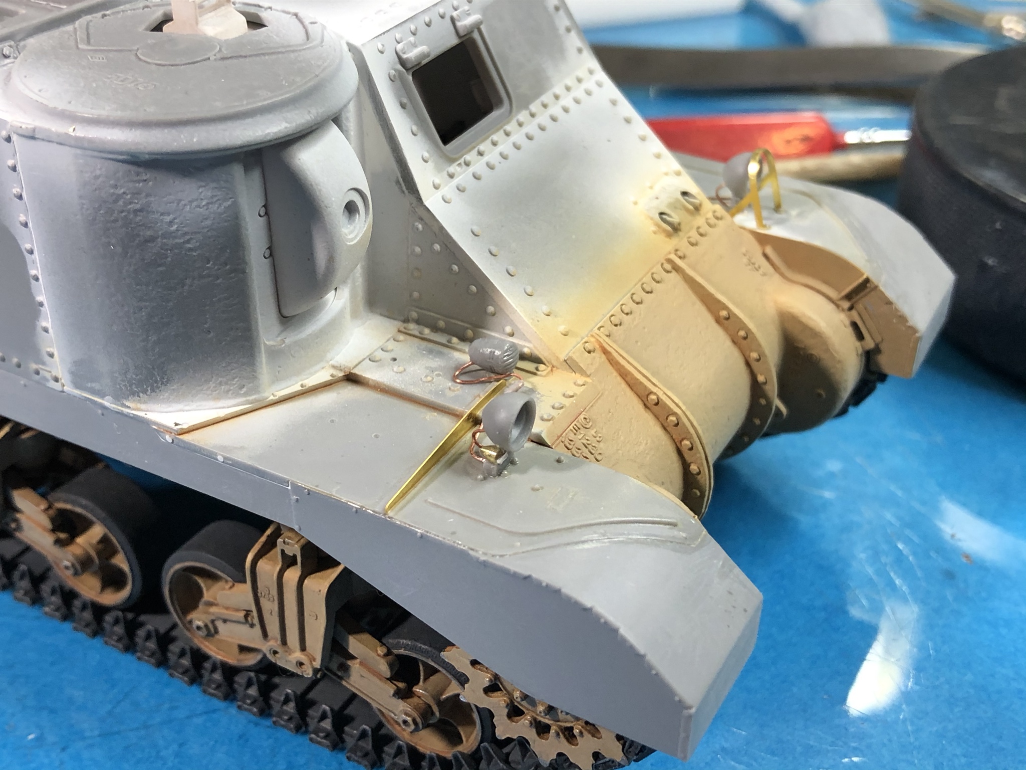
I managed to lose one of small light assemblies, so I had to make another on the lathe. Do to this problem I didnít have time to get the guard installed before the end of my modeling session. Luckily, thereís always tomorrow...

While the soldering gear was out I went ahead and took care of the basket for the right side fender.


The brackets are installed using CA glue. I just have pretty much reached the conclusion that I donít gain anything by attaching sheet styrene to the PE and then placing with standard cement. The parts stick up higher and are easier to knock off.

I wired and installed the light assembly on the left side and the bent and installed the guard.


I did the cleanup and wiring on the right side. I installed the fender support and completely reworked the siren do to a huge amount of mold offset.

I managed to lose one of small light assemblies, so I had to make another on the lathe. Do to this problem I didnít have time to get the guard installed before the end of my modeling session. Luckily, thereís always tomorrow...

PRH001

Joined: June 16, 2014
KitMaker: 681 posts
Armorama: 603 posts

Posted: Monday, February 17, 2020 - 02:46 PM UTC
Better late than never, here a few pics of the stowage basket and right side light guard.
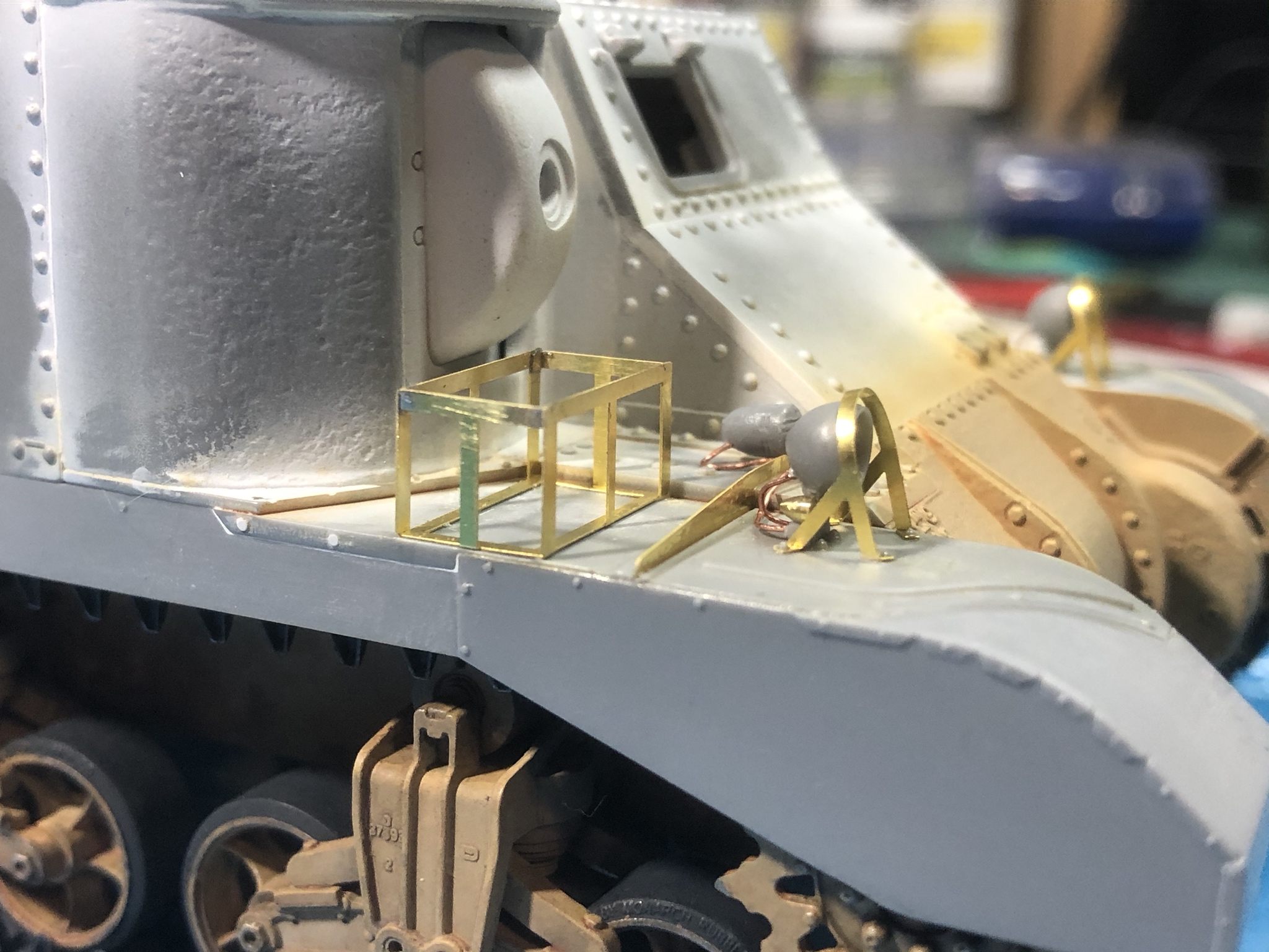

This week, I plan on working on the PE stowage support rails on the sides...


This week, I plan on working on the PE stowage support rails on the sides...
raivo74

Joined: November 09, 2009
KitMaker: 132 posts
Armorama: 109 posts

Posted: Tuesday, February 18, 2020 - 09:47 PM UTC
Neat soldering, Paul, keep it going.
I am no expert on Grant, but if I remember right, the hull MGs have been cancelled on Lees at some point and their apertures would be welded down. Have they decided to leave it on the British version?
I am no expert on Grant, but if I remember right, the hull MGs have been cancelled on Lees at some point and their apertures would be welded down. Have they decided to leave it on the British version?

PRH001

Joined: June 16, 2014
KitMaker: 681 posts
Armorama: 603 posts

Posted: Wednesday, February 19, 2020 - 06:16 AM UTC
Many of the Grants did have the hull openings welded over, but many did not. Early Grants were supposed to have the hull machine guns in place, and there was direction that the guns could be removed in the Apr-May Ď42 time frame. I have seen photos from that time period with guns in place, guns removed and the holes still visible and those with the ports welded closed. I would be very hesitant to say that a message indicating something may be done was put in place universally and in a specific manner once vehicles hit the field.
I will say that unless someone has specific photos of a specific vehicle on a specific day, the variables are too big to say for sure.
Donít know if that answers your question, but basically, it depends on the vehicle.
I will say that unless someone has specific photos of a specific vehicle on a specific day, the variables are too big to say for sure.
Donít know if that answers your question, but basically, it depends on the vehicle.

raivo74

Joined: November 09, 2009
KitMaker: 132 posts
Armorama: 109 posts

Posted: Wednesday, February 19, 2020 - 07:39 AM UTC
Thanks for clarification, Paul. 

pzandt

Joined: January 02, 2013
KitMaker: 68 posts
Armorama: 57 posts
Posted: Wednesday, February 19, 2020 - 06:19 PM UTC
Enjoy reading and watching your build so much, that I went out and got the same kit. Thanks for posting and for sharing the neat tricks and skills.

PRH001

Joined: June 16, 2014
KitMaker: 681 posts
Armorama: 603 posts

Posted: Thursday, February 20, 2020 - 01:21 AM UTC
Congrats on the new kit! Iíve really enjoyed working on mine. Iím also glad to hear youíre finding this build interesting. Hopefully it will stay that way ...
Cheers
Paul H
Cheers
Paul H
ivanhoe6

Joined: April 05, 2007
KitMaker: 2,023 posts
Armorama: 1,234 posts

Posted: Thursday, February 20, 2020 - 01:43 AM UTC
Morning Paul,
Thanks for all the track tips ! Especially draping the tracks over the brass tube to get in at the nooks & crannies. A simple solution to a problem, one that I never thought about and will use often now.
Thanks for that and taking the time to share with us and answer all of our questions!
Thanks for all the track tips ! Especially draping the tracks over the brass tube to get in at the nooks & crannies. A simple solution to a problem, one that I never thought about and will use often now.
Thanks for that and taking the time to share with us and answer all of our questions!

PRH001

Joined: June 16, 2014
KitMaker: 681 posts
Armorama: 603 posts

Posted: Thursday, February 20, 2020 - 04:57 PM UTC
Thanks for the kind words. Over the next few days I intend to post the process used to solder together the PE stowage rails located on the sides of the kit.
About five years ago, I posted an article on Armorama called Soldering Brass, Copper and Photo Etch which covers the equipment, tools, supplies and methods needed to solder. This was a general or generic piece and may be of some use to anyone interested.
The posts I intend to put in this build log will be focused on how I work through assembly of the items in this kit. Hopefully someone will find it useful.
Cheers
Paul H

PRH001

Joined: June 16, 2014
KitMaker: 681 posts
Armorama: 603 posts

Posted: Friday, February 21, 2020 - 01:26 AM UTC
Here is the first Installment on the Grant stowage rail assembly.
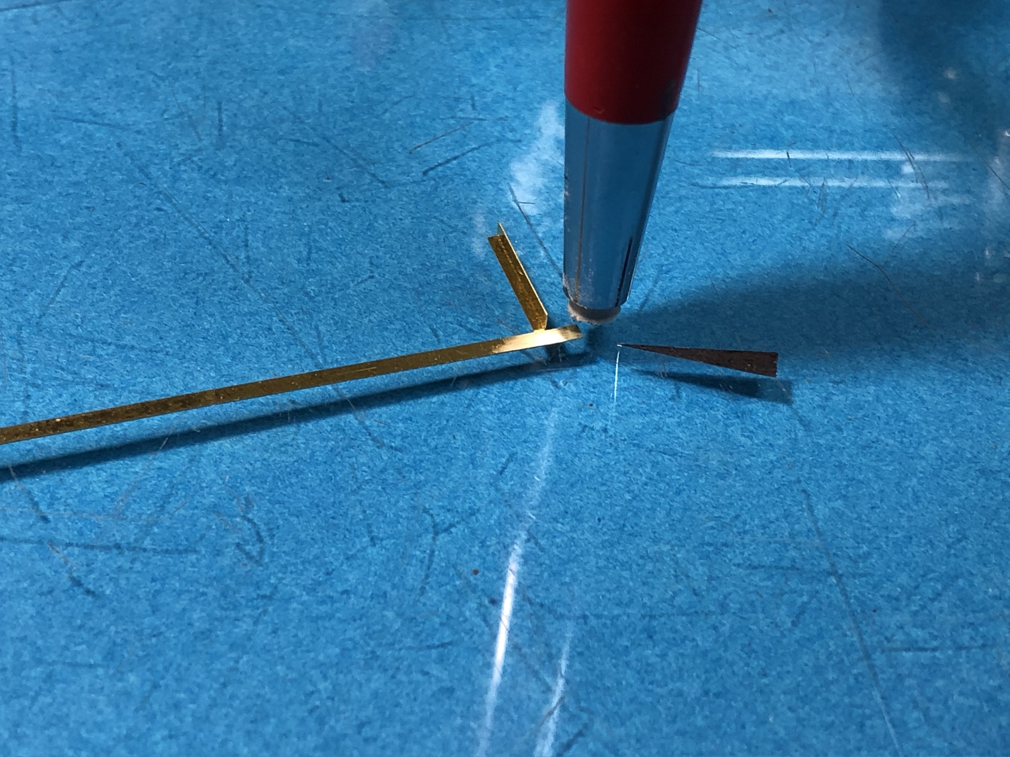
In this picture, the rail has been removed from the sheet and the attachment points cleaned up. The integral support bar has been bent to its 90 degree shape and the area for it attachment to the rail is cleaned for soldering with a glass fiber brush. Please note, when soldering, oxidation of the parts will interfere with the joints so we clean them before soldering and every time we apply heat.
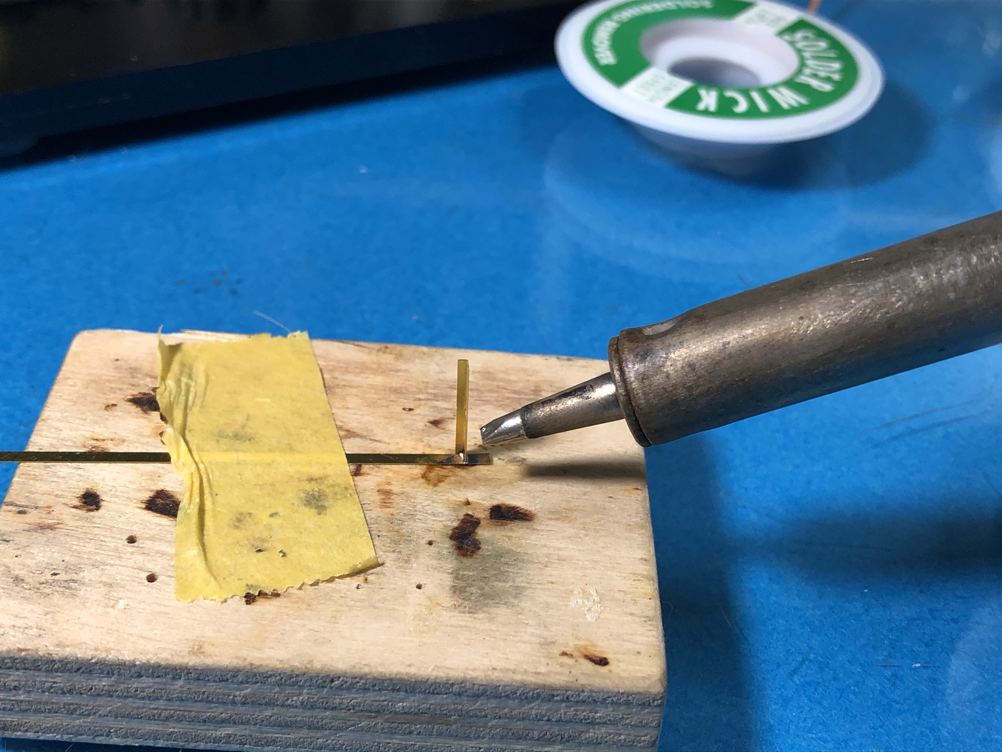
In this photo Iíve taped the rail to a small block of wood to prevent the piece from losing too much heat as it would on glass or metal surfaces. Iíve applied a small amount of flux and a small flake of solder to the area and tinned it to prepare for the joint.

Next Iíve bent the support bar into position and verified that itís straight from multiple angles.

Next, I apply flux to the area and place a very small flake of solder in the angle of the joint. This flake is cut from a roll of solder wire and is only about .5mm across.

Using the largest tip I can fit into the area to effect quick transfer, I touch the joint with the soldering iron. Heat from the iron melts the solder flake and pulls it into the joint.
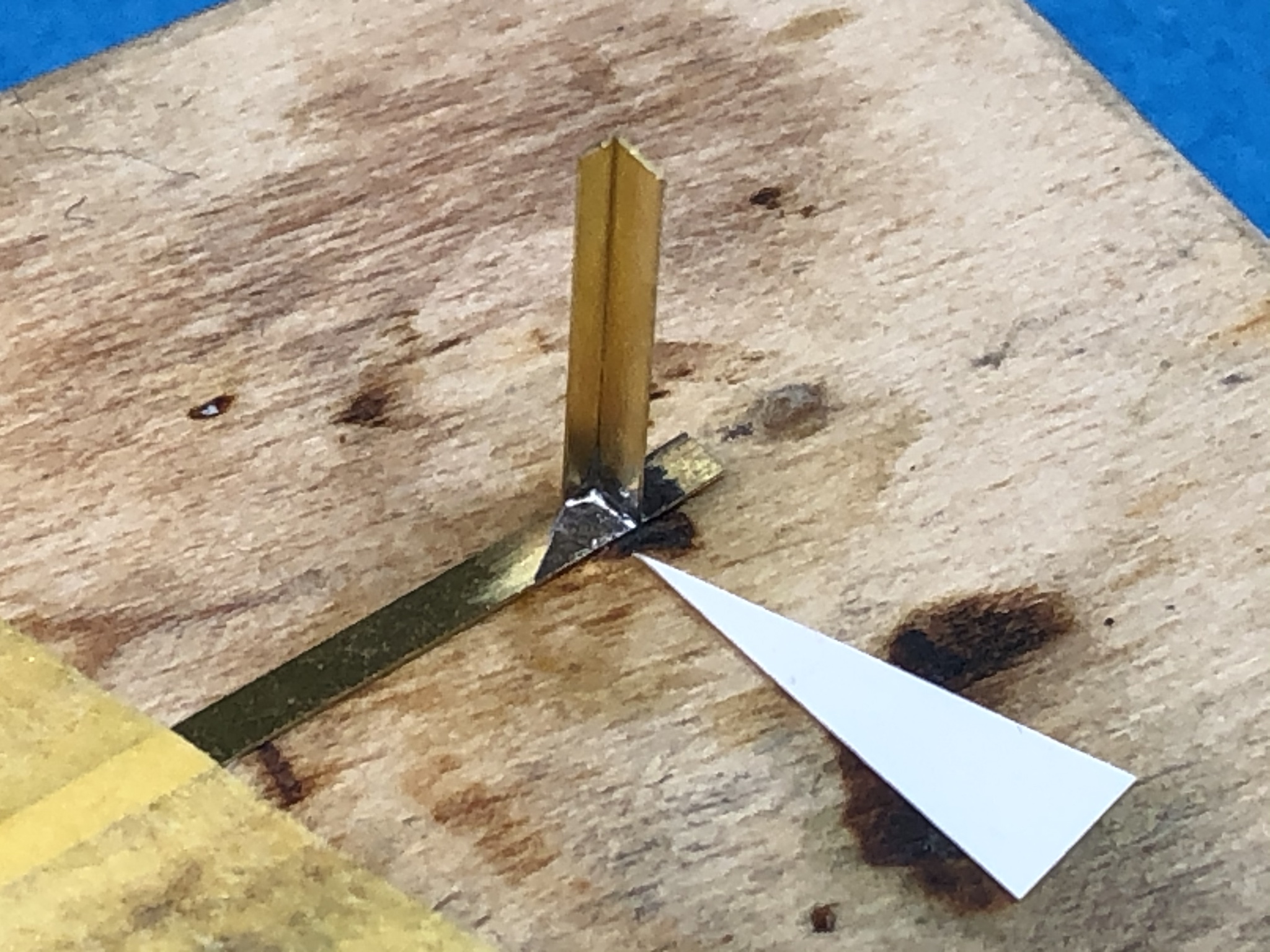
Here is the joint after the burnt flux is cleaned away using isopropyl alcohol and a small brush. Iím always looking for a smooth shiny fillet when finished. If the finish is rough and grainy, the joint needs to be redone. Please note that flux residue must always be cleaned for joint inspection and, more importantly, good paint adhesion.
End of installment one
In this picture, the rail has been removed from the sheet and the attachment points cleaned up. The integral support bar has been bent to its 90 degree shape and the area for it attachment to the rail is cleaned for soldering with a glass fiber brush. Please note, when soldering, oxidation of the parts will interfere with the joints so we clean them before soldering and every time we apply heat.

In this photo Iíve taped the rail to a small block of wood to prevent the piece from losing too much heat as it would on glass or metal surfaces. Iíve applied a small amount of flux and a small flake of solder to the area and tinned it to prepare for the joint.

Next Iíve bent the support bar into position and verified that itís straight from multiple angles.

Next, I apply flux to the area and place a very small flake of solder in the angle of the joint. This flake is cut from a roll of solder wire and is only about .5mm across.

Using the largest tip I can fit into the area to effect quick transfer, I touch the joint with the soldering iron. Heat from the iron melts the solder flake and pulls it into the joint.

Here is the joint after the burnt flux is cleaned away using isopropyl alcohol and a small brush. Iím always looking for a smooth shiny fillet when finished. If the finish is rough and grainy, the joint needs to be redone. Please note that flux residue must always be cleaned for joint inspection and, more importantly, good paint adhesion.

End of installment one
 |


