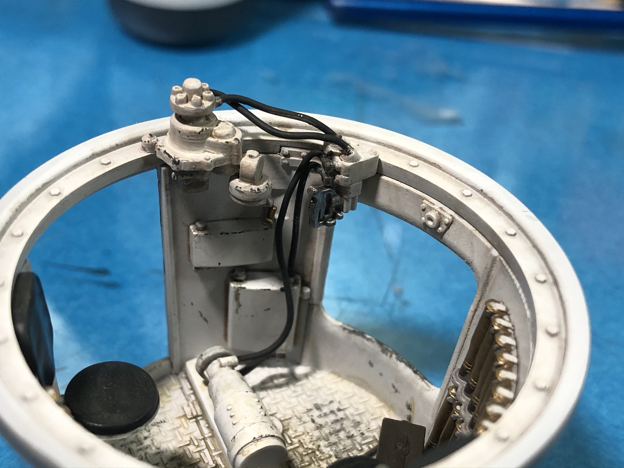
I made a bit more progress on the Grant from the last several evenings. I painted the turret drive controls Vallejo Stencil with a Vallejo Earth Brown wash and installed them onto the turret drive ring. According to the instructions, the lines for the drive are to be scratchbuilt so I made mine out of 20 thousandths solder. The lines are painted Vallejo Black Grey and the control handles were painted AK Interactive Brass and Vallejo Metal Color Duralumin respectively.
The last parts to go into the turret basket the seat and support. These were painted Tamiya White Primer for the frame and support and the seat pads were painted Vallejo Black Grey. A coat of Vallejo Semi gloss clear went over that and all of the seats received a very thin wash of Vallejo Buff to help cut the new look.
Here is the completed basket installed on the turret.
And here is a sneak peek of the turret and basket assemblies set in place and viewed through the left side door.
I’m planning on tackling the external fittings next and should be ready to start painting soon...
Cheers
Hosted by Darren Baker
MiniArt Grant w/interior build log interest?
PRH001
New Mexico, United States
Joined: June 16, 2014
KitMaker: 681 posts
Armorama: 603 posts
Joined: June 16, 2014
KitMaker: 681 posts
Armorama: 603 posts
Posted: Friday, March 20, 2020 - 12:38 PM UTC
Track_Slap
New South Wales, Australia
Joined: February 08, 2020
KitMaker: 3 posts
Armorama: 3 posts
Joined: February 08, 2020
KitMaker: 3 posts
Armorama: 3 posts
Posted: Friday, March 20, 2020 - 03:42 PM UTC
I'm still following your build Paul. Eagerly awaiting every installment. Thanks for sharing it. It's brilliant.
It's funny, I always thought Blu Tack was American. Obviously not. We've had it here since I was a kid (a long time ago). I use it modelling to hold things myself. Although I can honestly say I've never seen a hockey puck in the flesh!
PRH001
New Mexico, United States
Joined: June 16, 2014
KitMaker: 681 posts
Armorama: 603 posts
Joined: June 16, 2014
KitMaker: 681 posts
Armorama: 603 posts
Posted: Saturday, March 21, 2020 - 03:30 PM UTC
What??! You’ve never seen an key puck in the flesh? Oh, that’s right, they’re non-migratory...kind of like coconuts.
Thanks for taking the time to follow along!
PRH001
New Mexico, United States
Joined: June 16, 2014
KitMaker: 681 posts
Armorama: 603 posts
Joined: June 16, 2014
KitMaker: 681 posts
Armorama: 603 posts
Posted: Saturday, March 21, 2020 - 04:04 PM UTC
Ok. Today has been productive for the Grant, but it dang sure doesn’t seem like it!
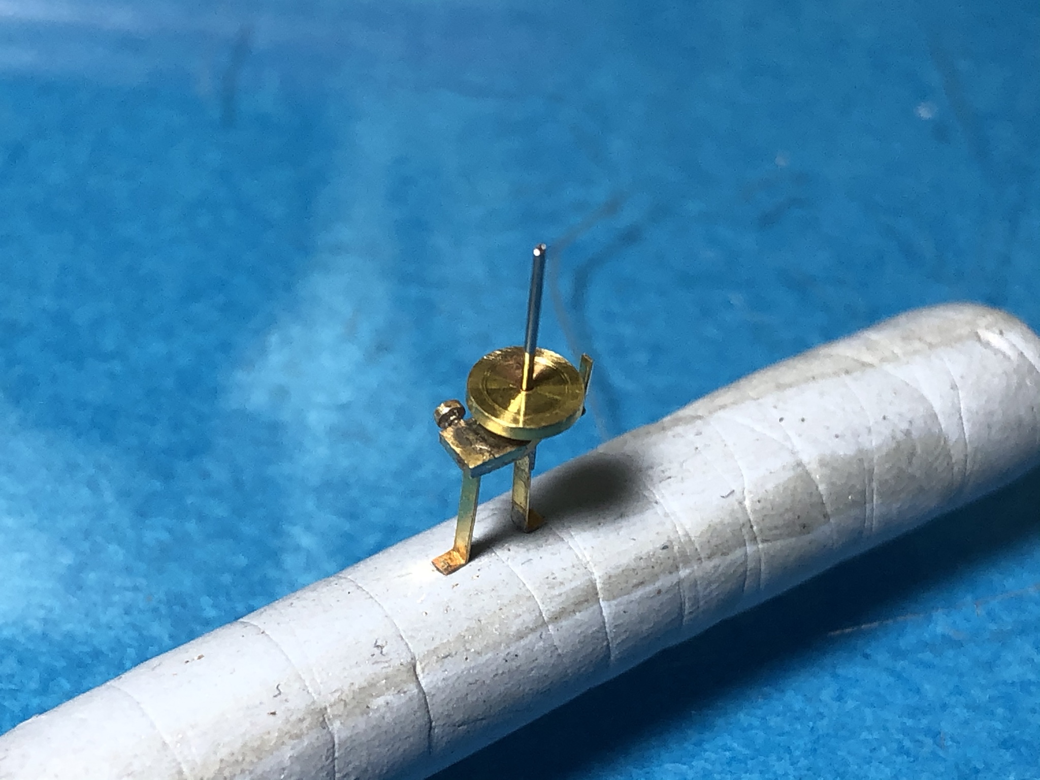
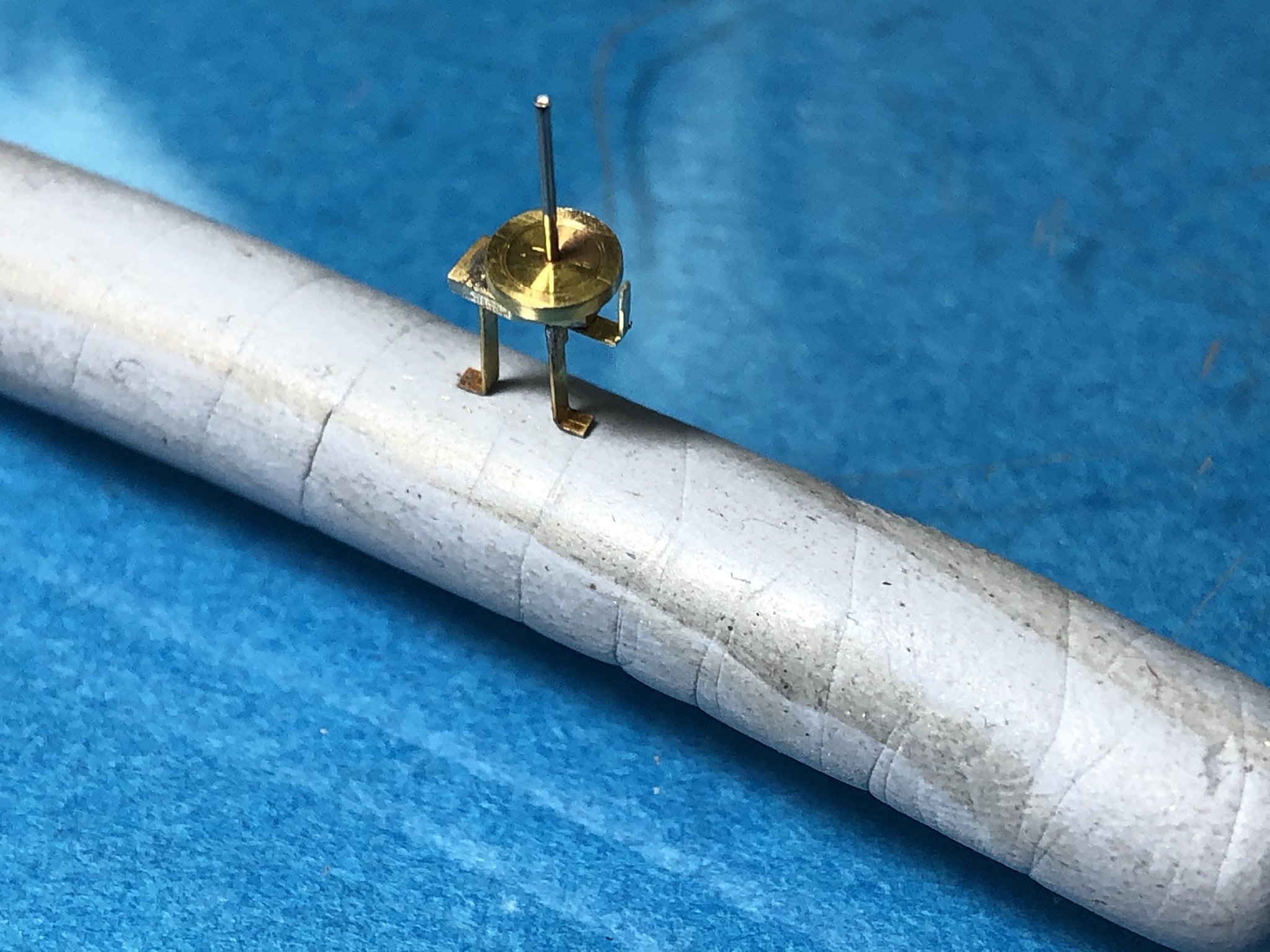
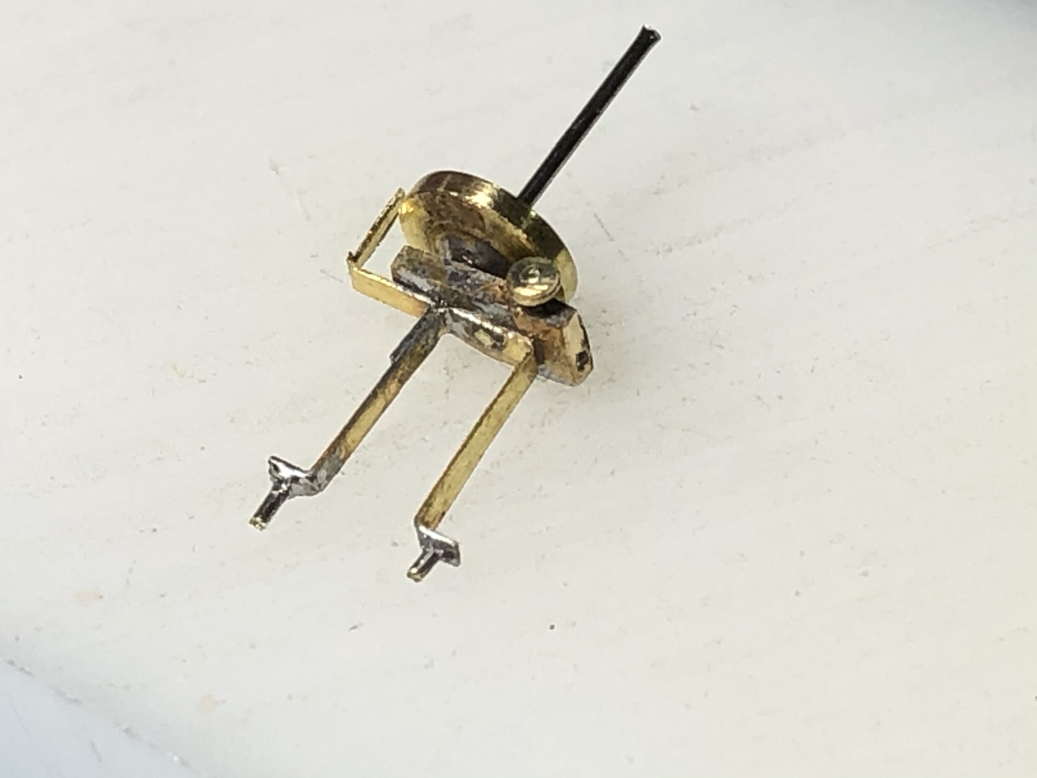
Like I said, I’ve moved on to some of the external fittings. First up is the wireless antenna base for the vehicle I’m currently intending to model. This Grant has a non-standard antenna location and it has no protective ring fixture on it. The parts in the kit would work for most installation with some careful cleanup, but not for my already alternate vehicle.
Looking around on the internet showed that most of the aftermarket available was located overseas and was again the wrong type for my model. Soooo, I decided to tackle the antenna mount with a bit of doing it myself.
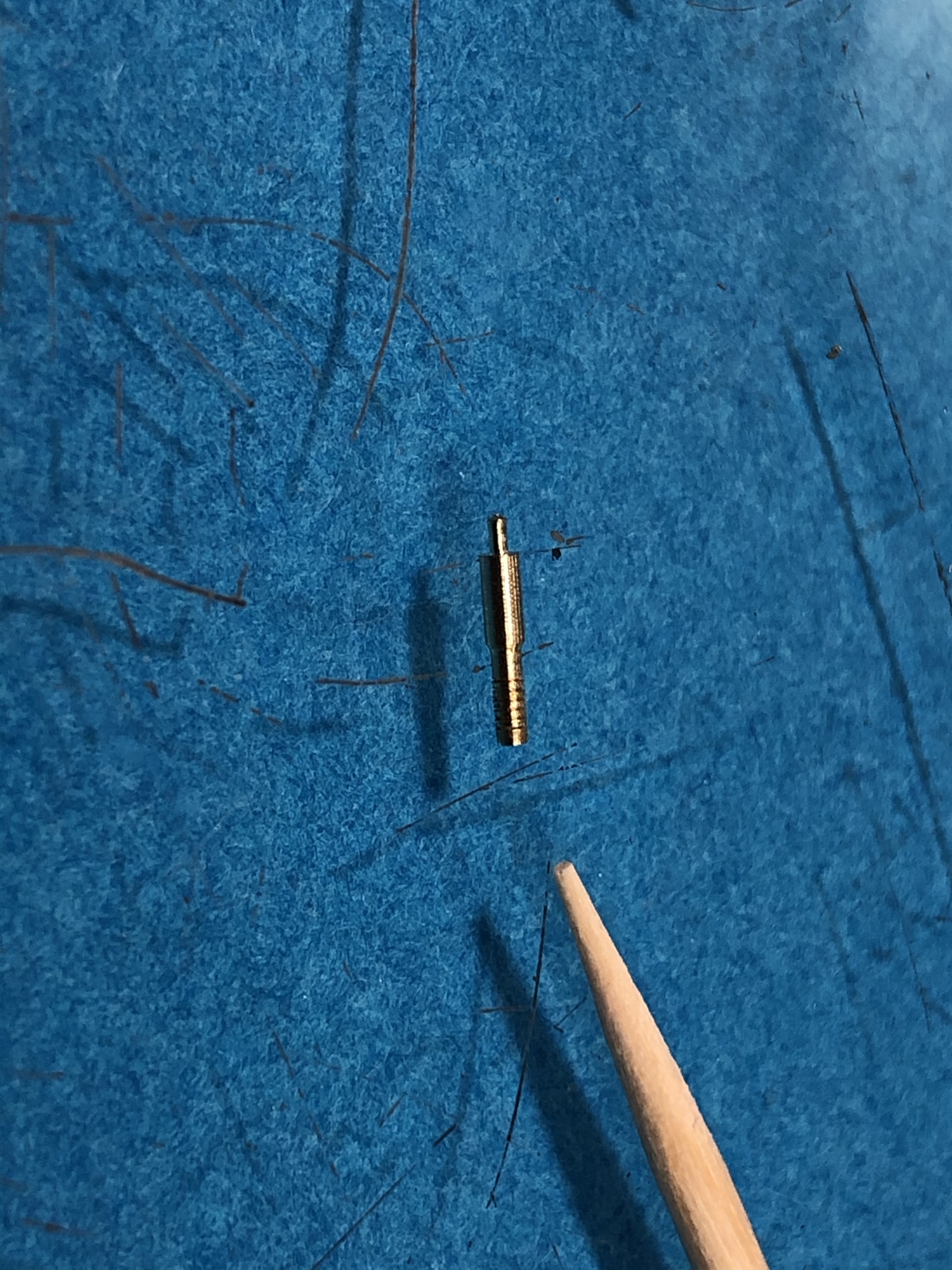
First, I turned the body out of brass and center drilled it.
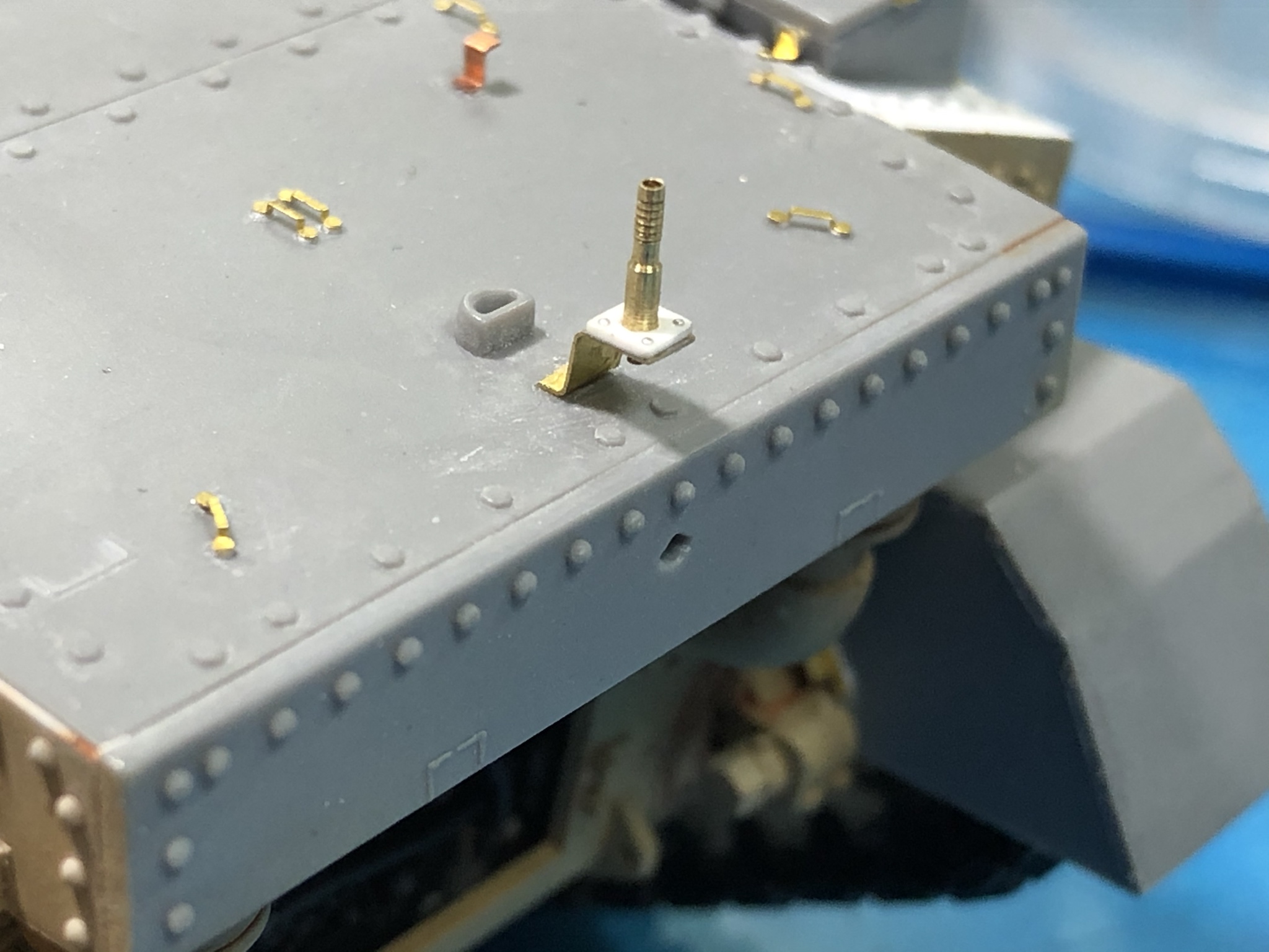
I then cut a piece of the PE fret to make the mount itself. I drilled a hole to match the lower end of the antenna body and made the bends based on photos of the vehicle.
Next, I soldered the antenna body to the mount bracket. Honestly, I thought I’d taken a picture of that step, but I must have missed it.
Next I drilled a pice of 10 thousandths styrene stock to match the lower portion of the antenna body, cut it to size and superglued it in place. I punched a couple of .5mm discs out of 5 thousandths metal foil and installed them on the base using Vallejo Clear gloss paint as the adhesive.
The mount was located and installed on the rear of the model as you can see here.
I spent the next hour or two researching the vane sights used on some Grants. Making it was pretty much just bending brass and soldering it together.
At this point, I was done with the fun for the day. Hopefully, these items will look the part in at the end of the build.
Cheers,
Paul H
deerstalker36
Queensland, Australia
Joined: May 16, 2010
KitMaker: 232 posts
Armorama: 218 posts
Joined: May 16, 2010
KitMaker: 232 posts
Armorama: 218 posts
Posted: Saturday, March 21, 2020 - 04:27 PM UTC
some serious skills there Paul
Dioramartin
New South Wales, Australia
Joined: May 04, 2016
KitMaker: 1,476 posts
Armorama: 1,463 posts
Joined: May 04, 2016
KitMaker: 1,476 posts
Armorama: 1,463 posts
Posted: Sunday, March 22, 2020 - 01:23 AM UTC
Yet another Aussie here admiring this build, exceptional work/workmanship
ivanhoe6
Wisconsin, United States
Joined: April 05, 2007
KitMaker: 2,023 posts
Armorama: 1,234 posts
Joined: April 05, 2007
KitMaker: 2,023 posts
Armorama: 1,234 posts
Posted: Sunday, March 22, 2020 - 01:35 AM UTC
Paul, I'm still following along and enjoying every post.
I mean 't to thank you earlier on your PE soldering seminar. EXCELLENT ! Up until that I was content to just bend and super glue PE. Intimidated by the thought of soldering. But with your tutorial
I'm going to give it a shot using old fret scraps. A quick question what wattage iron do you use? If I'm going to buy one I want to get it right the first time. And not end up frustrated by having a too weak one or too powerful one.
Thanks again for all your efforts and answering everybodies questions !
PRH001
New Mexico, United States
Joined: June 16, 2014
KitMaker: 681 posts
Armorama: 603 posts
Joined: June 16, 2014
KitMaker: 681 posts
Armorama: 603 posts
Posted: Sunday, March 22, 2020 - 03:40 AM UTC
I’d recommend you get an iron in the 35-50 watt range with temperature adjustment and interchangeable tips. Smaller irons will not transfer heat as well or as quickly for larger photoetch parts which can lead to cold solder joints that are weak or lumpy.
The interchangeable tips is because you want to use the largest tip that will fit into or against the soldered area to effect the most efficient heat transfer. Some people reshape their tips to do this but that leaves you with reshaping for the next project. It’s much easier to get replaceable tips and move quickly from project to project.
The temp adjustment is because you want solder to flow in no more tha 1-3 seconds from contact. If it takes longer than that, the flux will boil away and oxidation on the part will prevent a good joint. Small parts are easily damaged by roo much heat, so you turn down the heat for smaller areas and increase with for larger. Like I said, solder melt in 1-3 seconds is about right.
Amazon, eBay or other online retailers have soldering stations that meet these requirements pretty that are pretty inexpensive. I prefer Pace, Hakko or Weller soldering equipment but I’m sure the generic brands will probably work as well.
Hope this helps
PRH001
New Mexico, United States
Joined: June 16, 2014
KitMaker: 681 posts
Armorama: 603 posts
Joined: June 16, 2014
KitMaker: 681 posts
Armorama: 603 posts
Posted: Sunday, March 22, 2020 - 12:36 PM UTC
My Grant project for today... Brass rod, brass wire, hypodermic needle, lathe, mill, files, resistance soldering station, regular soldering station were all used on this item.
Here it is, test fit to the turret.
NobleRot
United States
Joined: January 16, 2020
KitMaker: 2 posts
Armorama: 1 posts
Joined: January 16, 2020
KitMaker: 2 posts
Armorama: 1 posts
Posted: Sunday, March 22, 2020 - 01:07 PM UTC
I’ve been following this build and it’s truly inspiring. You’ve outdone yourself on each stage. Can’t wait for the next update. Thanks
PRH001
New Mexico, United States
Joined: June 16, 2014
KitMaker: 681 posts
Armorama: 603 posts
Joined: June 16, 2014
KitMaker: 681 posts
Armorama: 603 posts
Posted: Monday, March 23, 2020 - 12:29 AM UTC
I appreciate all of the comments, both with offering support and those offering ways to improve the end result! It takes a while for someone who builds as slowly as I do to make it through these 1,000+ part kits. I’m learning as I go along on this project so I appreciate both your interest and your patience as I plod through this project.
phil2015
Illinois, United States
Joined: July 27, 2015
KitMaker: 502 posts
Armorama: 325 posts
Joined: July 27, 2015
KitMaker: 502 posts
Armorama: 325 posts
Posted: Monday, March 23, 2020 - 07:49 AM UTC
This is terrific. Thanks for documenting it. I've never wanted to do a kit with an interior before I saw this. Inspiring!
PRH001
New Mexico, United States
Joined: June 16, 2014
KitMaker: 681 posts
Armorama: 603 posts
Joined: June 16, 2014
KitMaker: 681 posts
Armorama: 603 posts
Posted: Monday, March 23, 2020 - 11:09 AM UTC
Thanks! It’s away nice to know others appreciate what you do. It helps keep the energy up when you’re working through the cleanup and assembly of track links!
PRH001
New Mexico, United States
Joined: June 16, 2014
KitMaker: 681 posts
Armorama: 603 posts
Joined: June 16, 2014
KitMaker: 681 posts
Armorama: 603 posts
Posted: Saturday, March 28, 2020 - 03:40 PM UTC
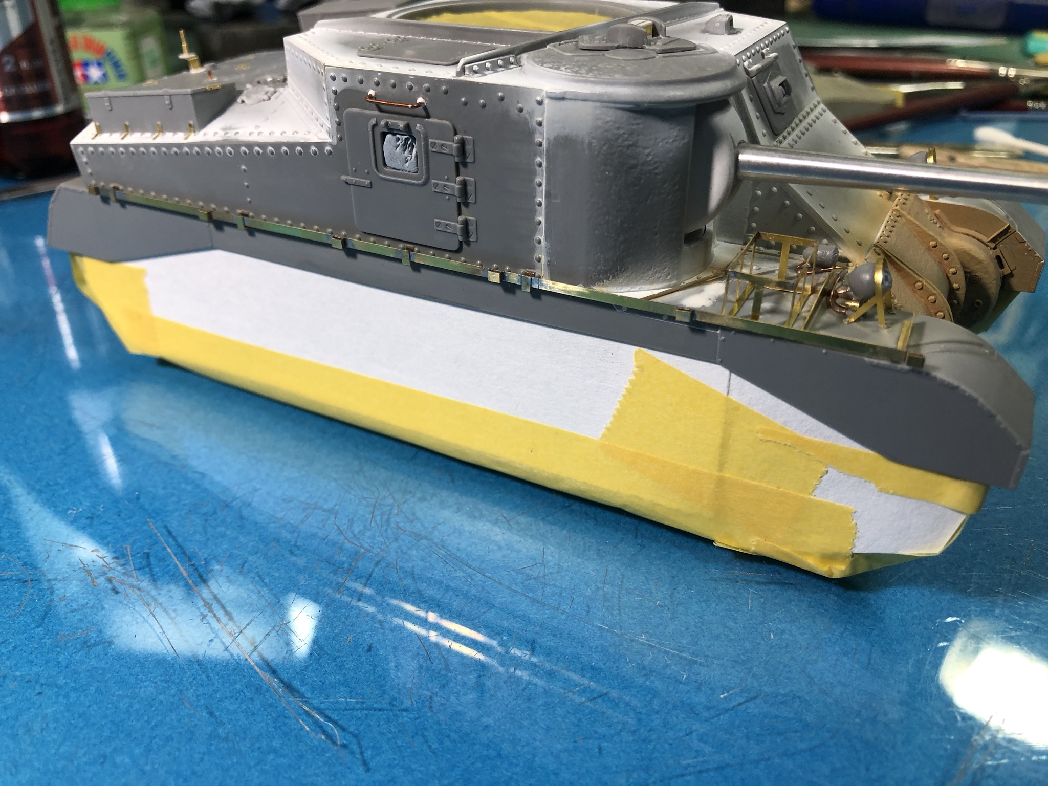
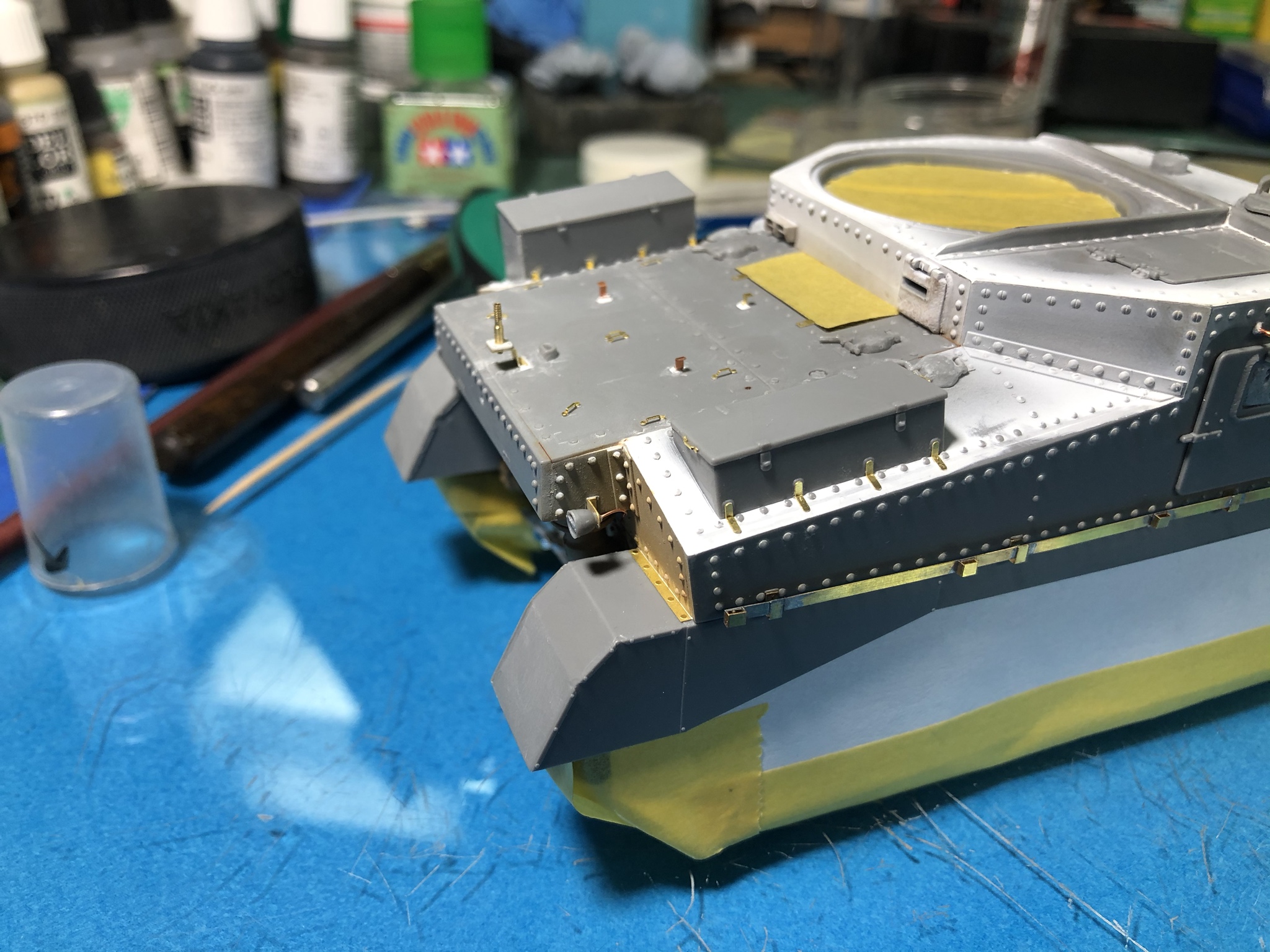
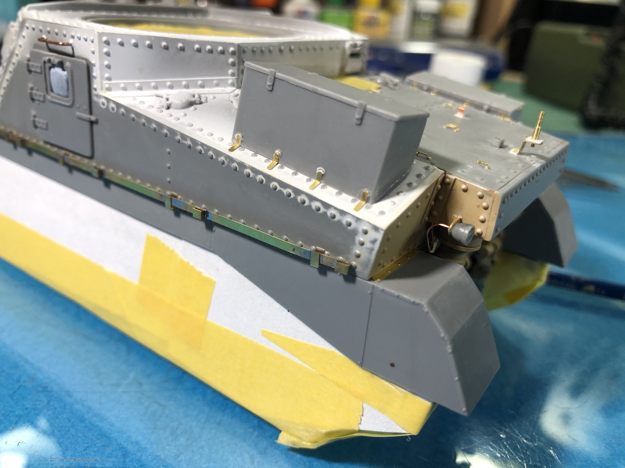
I made a bit of progress on the Grant. I installed temporarily installed the doors with a small amount of white glue to allow painting. I also masked any openings with tape or BluTack, and I masked off the running gear to preserve the previous work done there.
Once the masking was in place, I installed the stowage rails on vehicle sides using CA glue.
One note on this is that the forward most hanger location on the right side rail is marked incorrectly on the PE piece. I had to desolder the hanger and move it rearward approximately 1.5mm to get the hanger to match the location on the kit.
Next I wired and installed the tail lights.
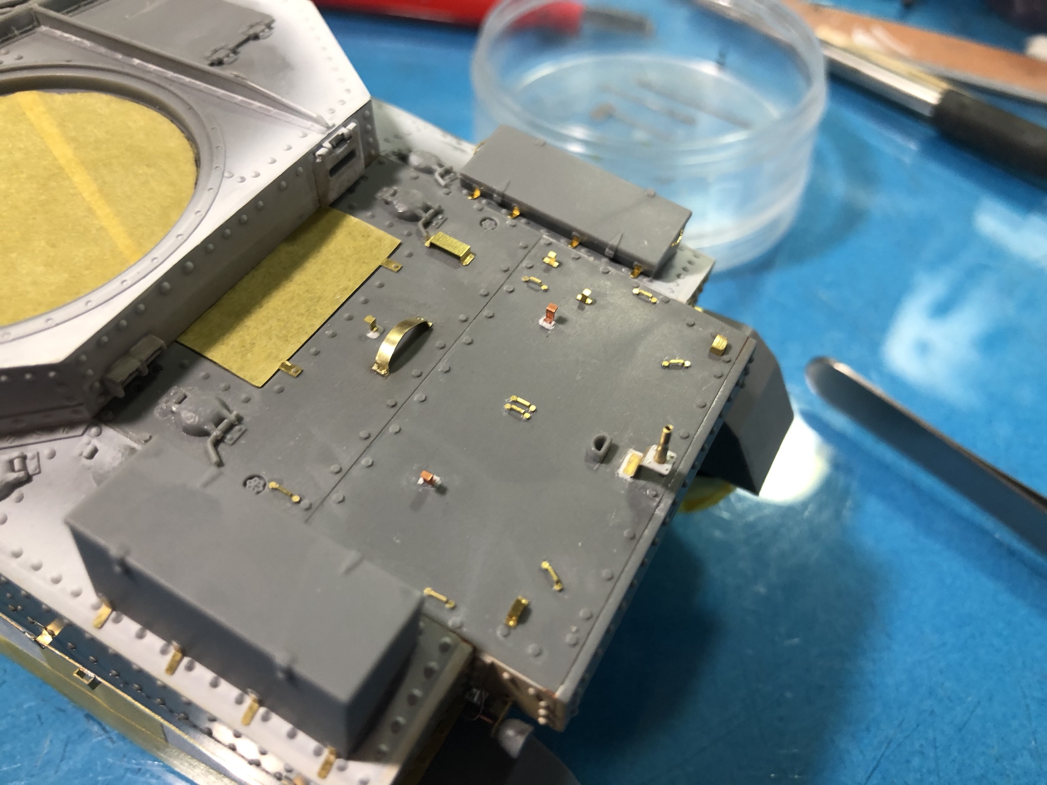
Next step was to install the PE holder for the tools on the rear deck.
Here are the tools set in place. They will not be installed until after I finish painting the exterior.
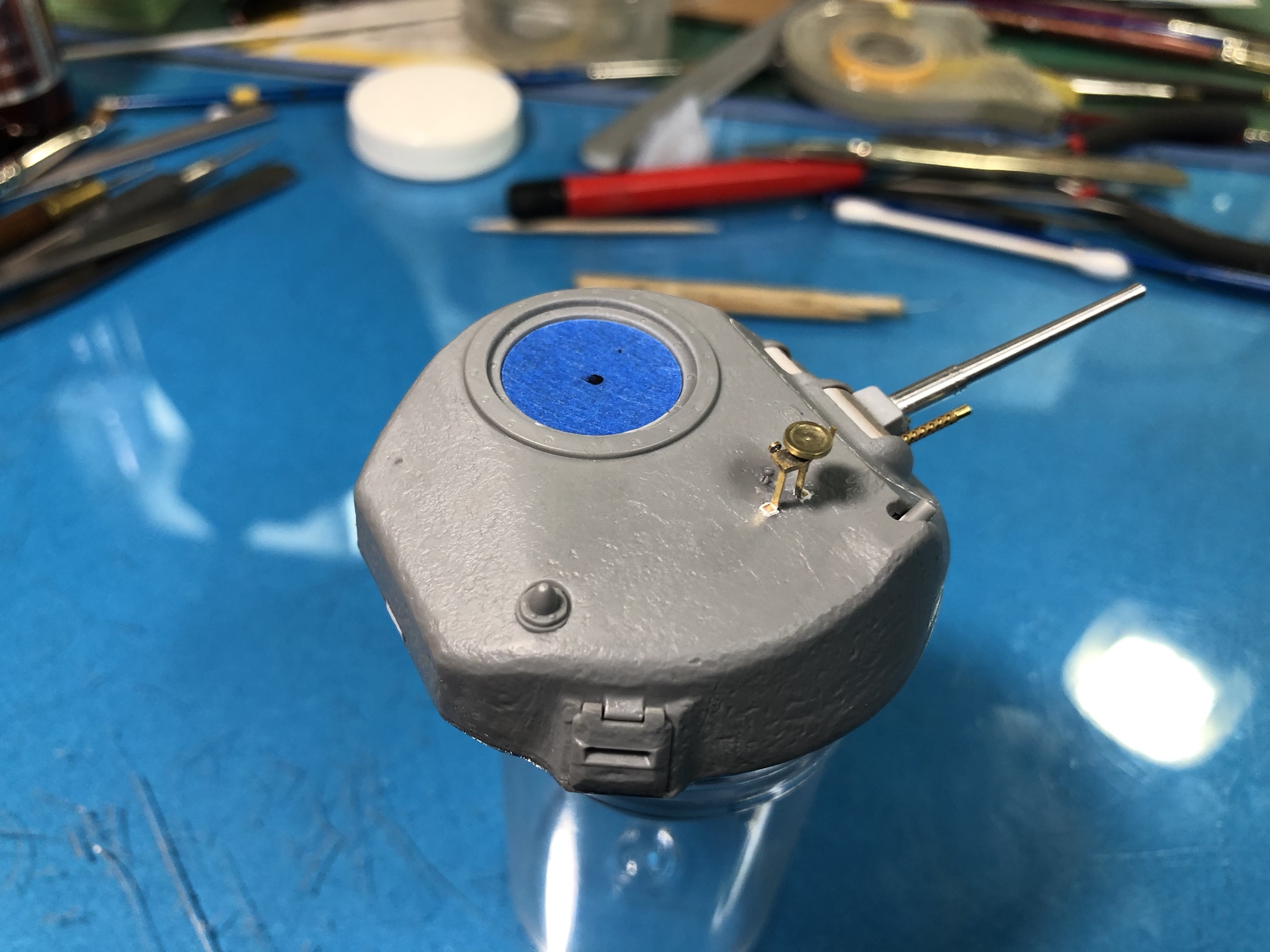
And the last portion of this update is on the turret. I removed the mounting location for the wireless antenna on the left rear of the turret top, filled the hole with CA glue and created cast texture in that area. I also went ahead and drilled the turret and installed the sun compass I made.
So, it looks like it’s about time to move on to the painting portion of this build...
Cheers all and I hope everyone is staying healthy.
ivanhoe6
Wisconsin, United States
Joined: April 05, 2007
KitMaker: 2,023 posts
Armorama: 1,234 posts
Joined: April 05, 2007
KitMaker: 2,023 posts
Armorama: 1,234 posts
Posted: Saturday, March 28, 2020 - 11:52 PM UTC
Congrats Paul ! The finish line is in sight ! Can't wait to see it with some paint.
Any thoughts how you're going to display the Grant?
PRH001
New Mexico, United States
Joined: June 16, 2014
KitMaker: 681 posts
Armorama: 603 posts
Joined: June 16, 2014
KitMaker: 681 posts
Armorama: 603 posts
Posted: Sunday, March 29, 2020 - 04:01 AM UTC
I haven’t really thought about displaying the Grant at all. I’m very much someone who is fascinated by the machine, versus the situation. Trying to place items in a vignette or diorama is another art form and I appreciate the gorgeous work done by those who do that type of display, but I’ll move on to the next interesting machine before doing anything like that. As a matter of fact, you’ll see a very minimal amount of stowage, if any, on pieces that I build. That’s not to say, those who add lots of stowage are in any way wrong, it’s just that too much stowage tends to hide the machine’s lines and details that captured my interest to begin with.
At most, I’ll do a small, simple base that won’t take up too much room in one of my display cabinets.
Cheers
At most, I’ll do a small, simple base that won’t take up too much room in one of my display cabinets.
Cheers
PRH001
New Mexico, United States
Joined: June 16, 2014
KitMaker: 681 posts
Armorama: 603 posts
Joined: June 16, 2014
KitMaker: 681 posts
Armorama: 603 posts
Posted: Monday, March 30, 2020 - 01:04 PM UTC
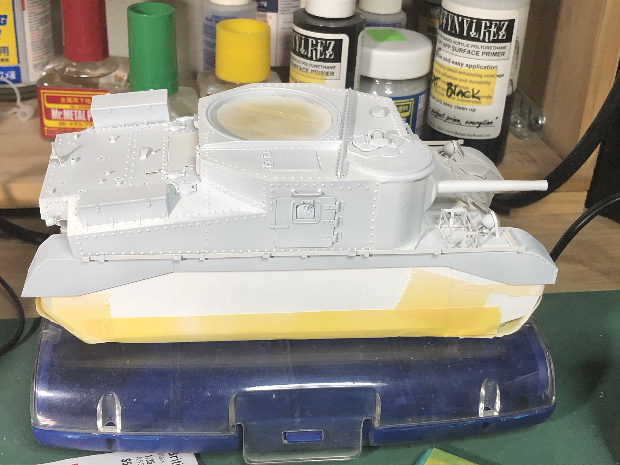
Moving forward with painting the Grant. First up priming with Tamiya White Primer. This was thinned 50% with Tamiya Lacquer Thinner. No attempt was made to ensure complete coverage, just enough primer to ensure good bite for the color coats.
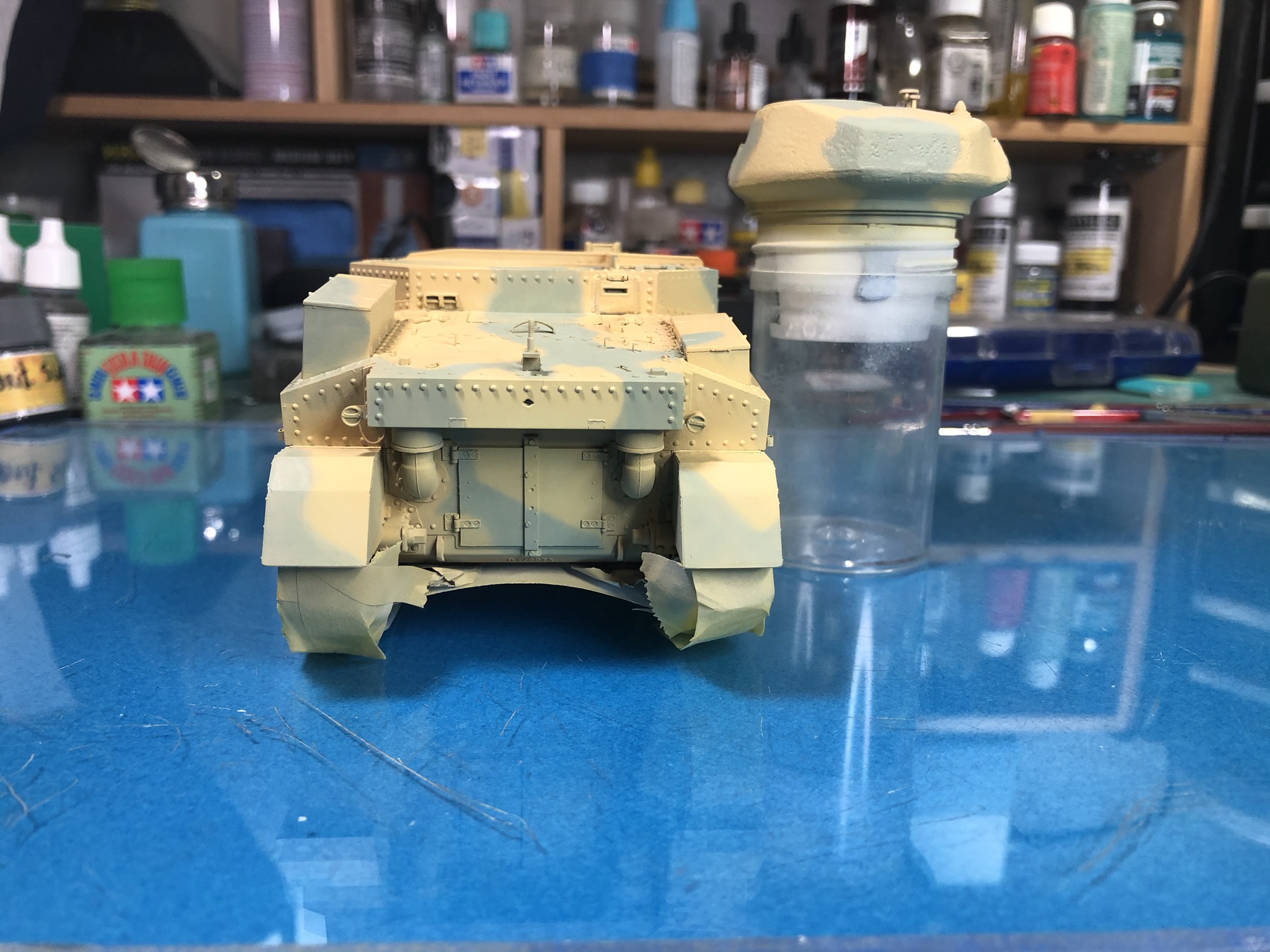
The primer dry and was scent free in about 6 hours, so it was time to apply the first color coat. The color was mixed from Tamiya paints starting with Mike Starmer’s suggested mix for BSC 61 Light Stone and then lightened to be less intense for this scale.
This color coat was applied in thin coats and built up slowly at low pressure to try and keep grain from building up due to the turbulence caused by all of the sharp angles on the kit.
Cheers all
PRH001
New Mexico, United States
Joined: June 16, 2014
KitMaker: 681 posts
Armorama: 603 posts
Joined: June 16, 2014
KitMaker: 681 posts
Armorama: 603 posts
Posted: Tuesday, March 31, 2020 - 12:24 PM UTC
The second color is on the Grant and drying. The Silver Grey color was mixed from Tamiya paints using Mike Starmer’s mix suggestions and lightened slightly for scale and to prevent too much darkening from washes.
The color was applied at low pressure (10 psi) through a .2mm tipped airbrush. The paint was thinned 1 part paint to 2 parts X-20A thinner and two or three drops of Tamiya Retarder was added to slow drying and to help prevent tip dry. The patten was drawn on very lightly with a colored pencil and applied freehand.
Cheers
PRH001
New Mexico, United States
Joined: June 16, 2014
KitMaker: 681 posts
Armorama: 603 posts
Joined: June 16, 2014
KitMaker: 681 posts
Armorama: 603 posts
Posted: Wednesday, April 01, 2020 - 02:10 PM UTC
Next Grant update. Third color is Slate from Lifecolor applied with a #1 brush.
KoSprueOne
Myanmar
Joined: March 05, 2004
KitMaker: 4,011 posts
Armorama: 1,498 posts
Joined: March 05, 2004
KitMaker: 4,011 posts
Armorama: 1,498 posts
Posted: Thursday, April 02, 2020 - 07:38 AM UTC
Details and paint is looking good, Sir.
It's reminding me of the cover photo on the first edition of, How to Build Dioramas by Sheperd Paine.
PRH001
New Mexico, United States
Joined: June 16, 2014
KitMaker: 681 posts
Armorama: 603 posts
Joined: June 16, 2014
KitMaker: 681 posts
Armorama: 603 posts
Posted: Thursday, April 02, 2020 - 03:00 PM UTC
I certainly appreciate the kind words.
Cheers!
Cheers!
PRH001
New Mexico, United States
Joined: June 16, 2014
KitMaker: 681 posts
Armorama: 603 posts
Joined: June 16, 2014
KitMaker: 681 posts
Armorama: 603 posts
Posted: Friday, April 03, 2020 - 01:02 PM UTC
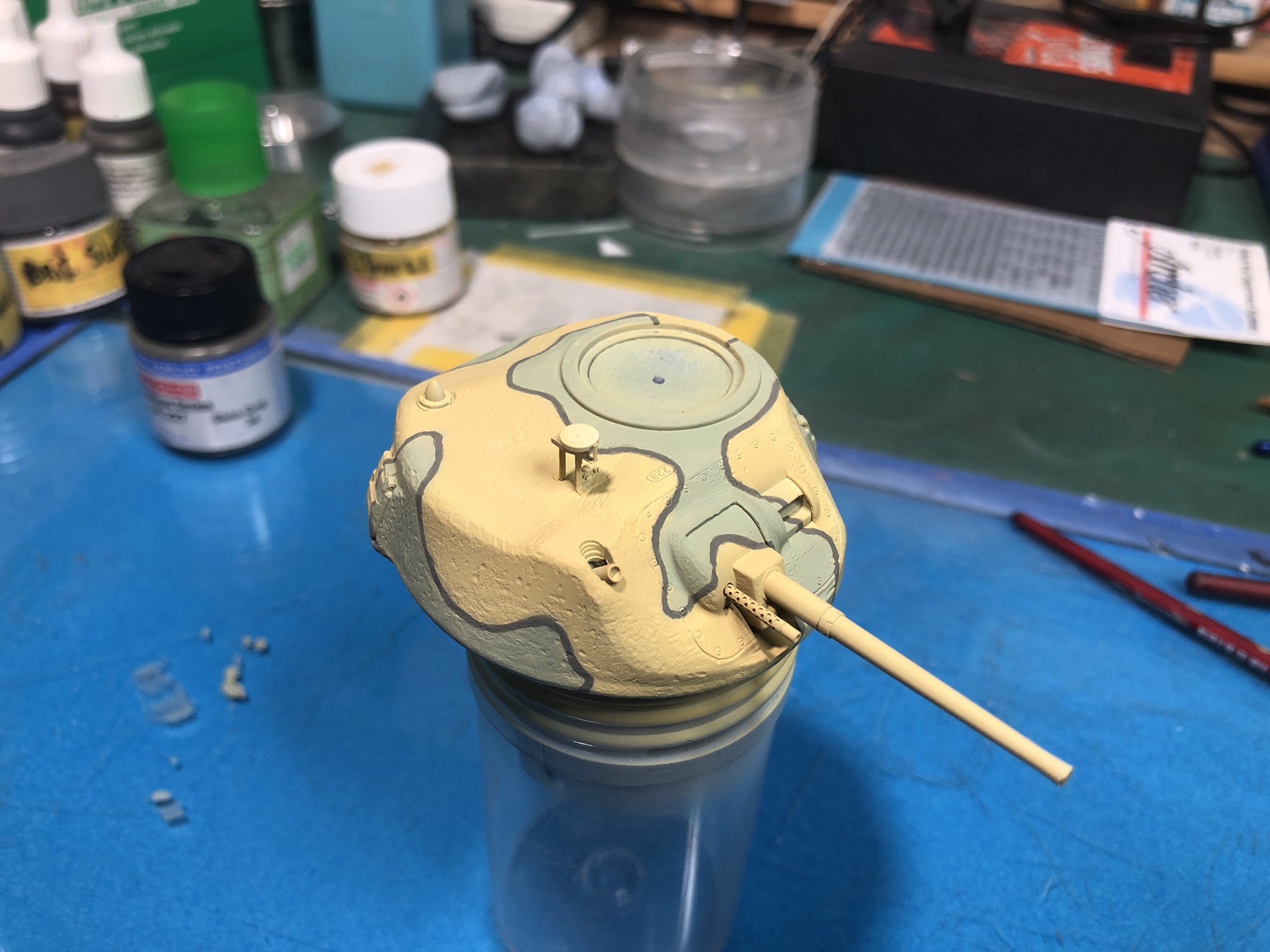
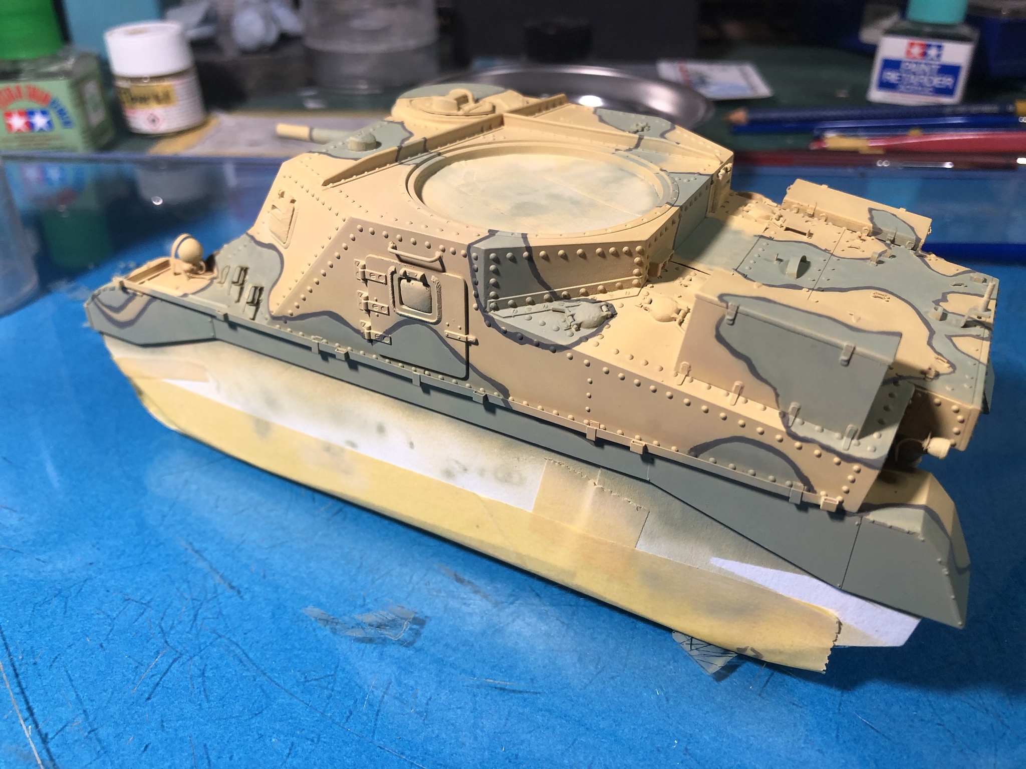
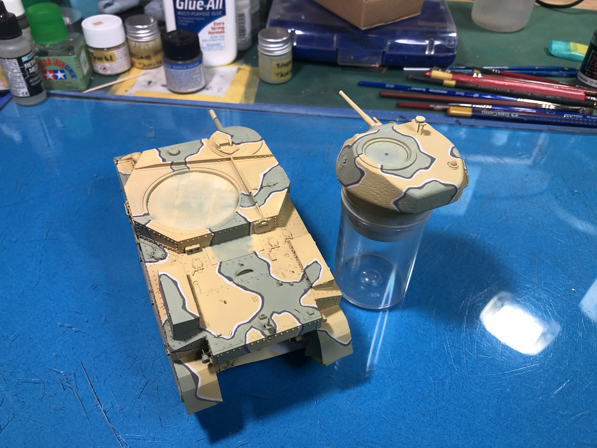
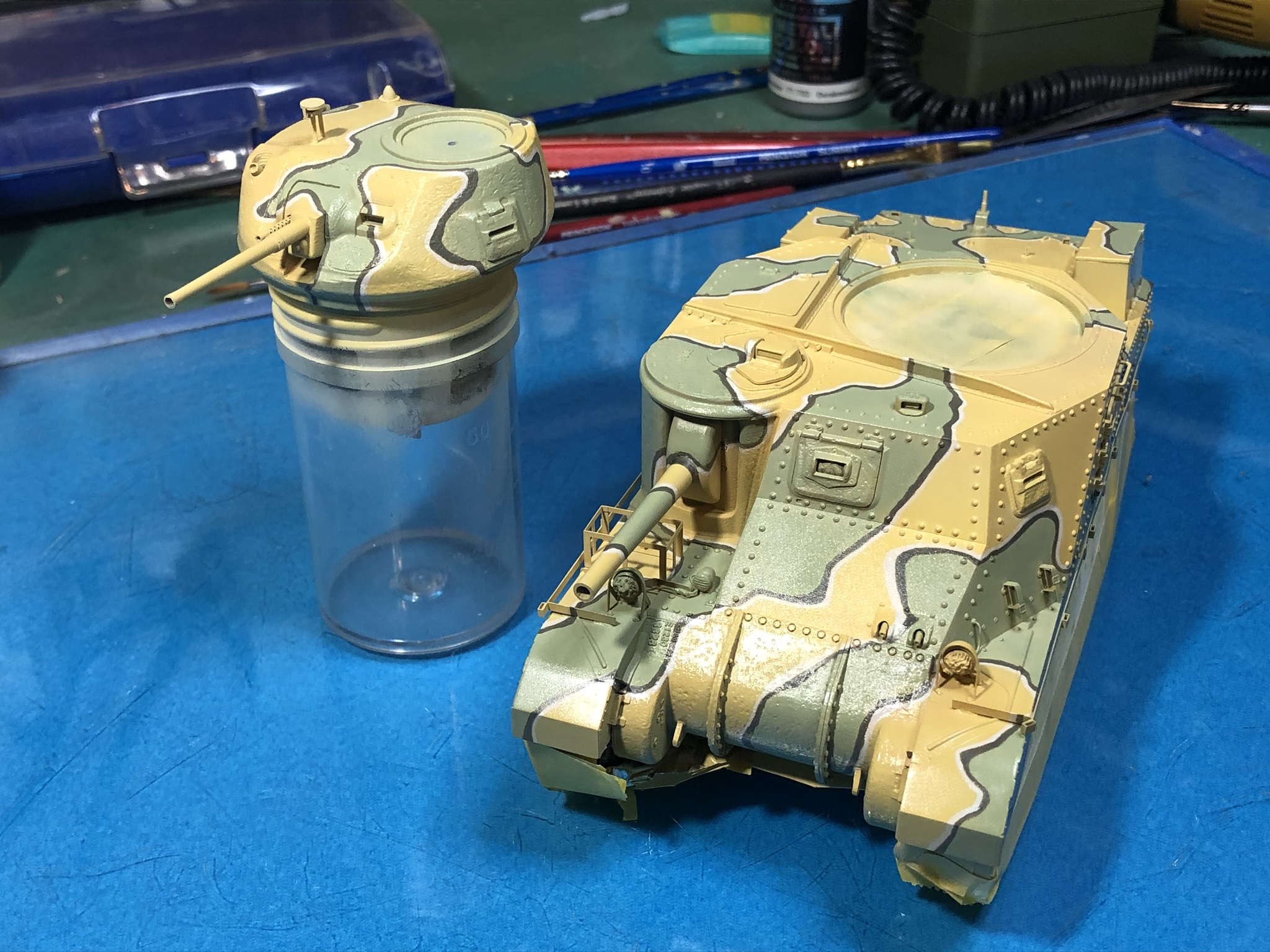
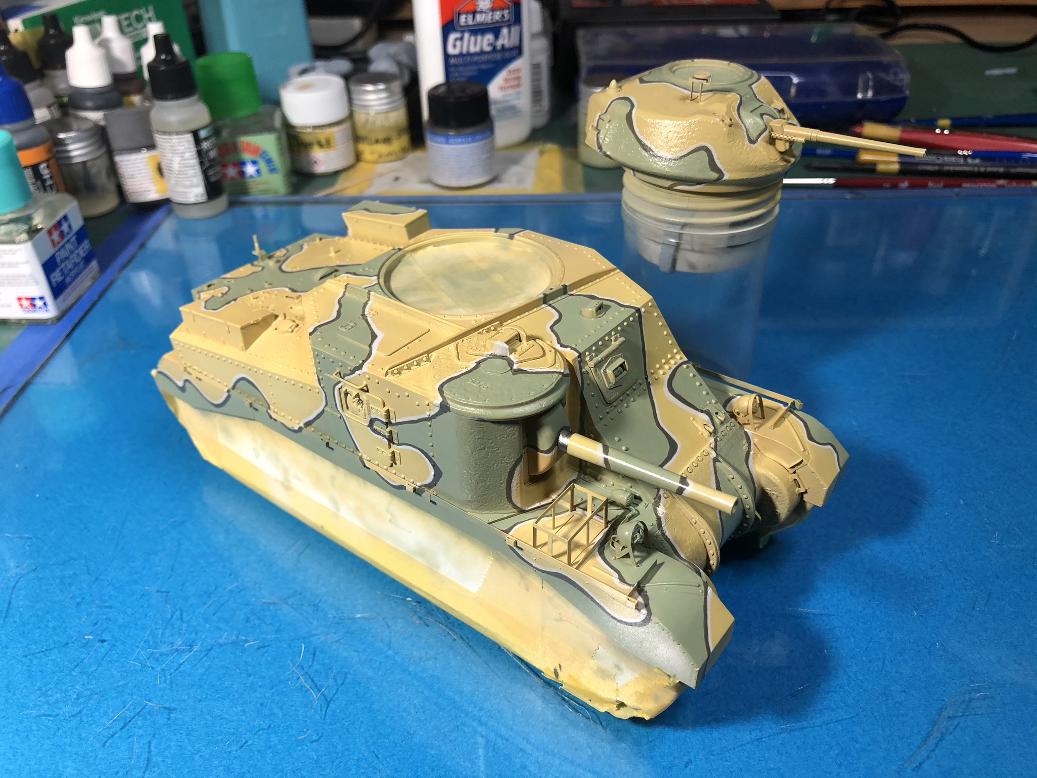
Here is the latest on the Grant with the fourth color applied to the camo pattern. The color used is Vallejo Stencil (off white) to make sure the white doesn’t overpower the other tones. It was applied in extremely thin layers with a No. 0 brush to prevent caking of the white paint.
The first picture is the flat surface finish as applied.
The rest of the images are following the clear Tamiya gloss coat I applied to allow application of markings.
Hope someone finds this info useful or interesting. As a humorous side note, due to my very slow hand painting methods, the Slate and Stencil lines took more time to complete than the track assemblies...
Cheers all!
raivo74
Vilnius, Lithuania
Joined: November 09, 2009
KitMaker: 132 posts
Armorama: 109 posts
Joined: November 09, 2009
KitMaker: 132 posts
Armorama: 109 posts
Posted: Friday, April 03, 2020 - 08:10 PM UTC
Great work, Paul. I noticed prominent seams on exhausts, are they present on a real thing either?
PRH001
New Mexico, United States
Joined: June 16, 2014
KitMaker: 681 posts
Armorama: 603 posts
Joined: June 16, 2014
KitMaker: 681 posts
Armorama: 603 posts
Posted: Saturday, April 04, 2020 - 02:59 AM UTC
Hi Raimondas!
Yes those are weld seams and they are clearly visible on the the real Grants and Lees with the early style exhaust system.
Cheers
Yes those are weld seams and they are clearly visible on the the real Grants and Lees with the early style exhaust system.
Cheers
Dioramartin
New South Wales, Australia
Joined: May 04, 2016
KitMaker: 1,476 posts
Armorama: 1,463 posts
Joined: May 04, 2016
KitMaker: 1,476 posts
Armorama: 1,463 posts
Posted: Saturday, April 04, 2020 - 02:30 PM UTC
Great progress, I’ll bet it took some cojones to start that hand-painting. I’m no expert on that scheme but it looks good, how are you intending to fade it?