

Superb work as always Bubba!
J
Hosted by Darren Baker
Riich Models RV35011

jrutman

Joined: April 10, 2011
KitMaker: 7,941 posts
Armorama: 7,934 posts
Posted: Saturday, August 17, 2013 - 12:03 AM UTC
SdAufKla
Joined: May 07, 2010
KitMaker: 2,238 posts
Armorama: 2,158 posts

Posted: Saturday, August 17, 2013 - 09:44 AM UTC
@ Keith: Yea! Those dirty rats and their flashlight, and turn tables, and desk lamps... 
Oh, wait a minute... What are we talking about?! You and me, we are a couple of those rats!
I won't tell if you won't...
In regards to the suspension. We'll see, won't we? It looks like it should go together pretty well, and if the fit of the parts that I've constructed so far is any indication, I think it's gonna be very nice indeed.
@ Jerry: As always, brother! Safe travels.
So, on to the build...
My next task has been to finish the engine compartment side walls so that I can close up the compartment and move along.
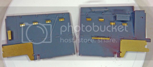
There are several PE parts that go onto the outsides of each side wall. The maintenance doors have a pair of finger lifts (four on each side, Pb 36) that must be formed and glued on.
The instructions would have you do this steps 20 and 21. Back in step 19, there's a PE ledge (Pa 7) for the radio operator's seat that's added to the right hand side wall, and back again in step 21, there's a PE holder (Pb 26) for some sort of small cleaning brush (J10). There are also PE side panels added to each side wall (Pb 21 and 14) that are added in step 16.
I decided to add all of these parts at once before adding the side walls to the engine compartment. I believe that this will make assembly and painting easier.
Here're the side walls with these parts added:
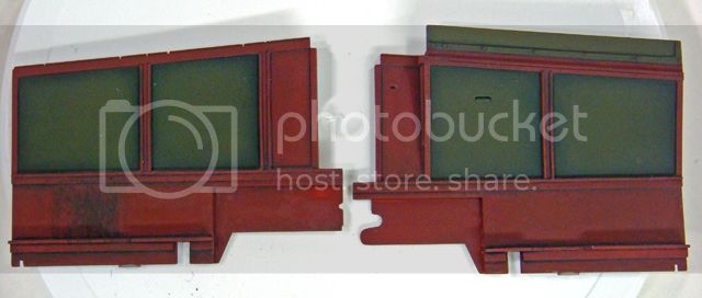
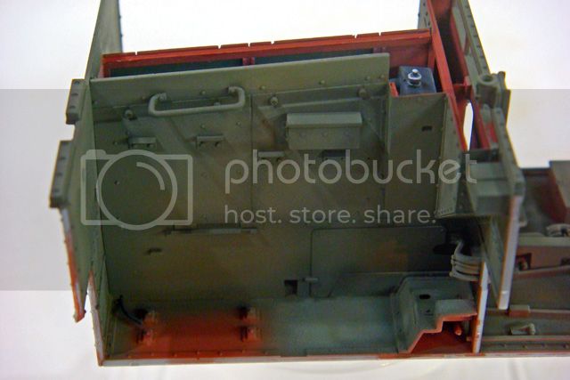
Next up was painting and weathering the interiors of these walls. I had already shot their insides with primer red, but I wanted some contrasts and visual interests, so I masked and painted the interiors of the inspection / maintenance doors the basic exterior color, G3 Green.
I used Mike Starmer's Tamiya paint mix formulas for this color. After I shot the basic color, for scale lighting and a little post-shading, I lightened the G3 with Tamiya Dark Yellow.
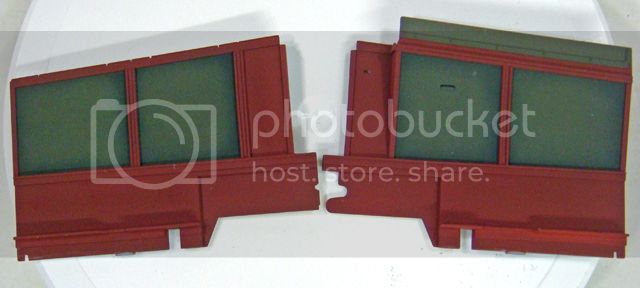
The interior side walls were then weathered using the same colors and steps as for the fire wall, rear hull wall, and floor.
In between waiting for painting steps to dry, I worked on the battery tray and its mounts. The instructions have you build the entire assembly and install it in step 13. The front of the battery tray is supported by a PE ledge (Pa4) that mounts to three small pins on the bottom left rear of the firewall which isn't installed until step 17. In the meantime, the batteries and their tray are supported by two small styrene feet (E4 and E5).
I thought assembly would be easier if I changed this sequence and installed the PE ledge to the firewall now, added the styrene feet to the bottom of the tray and then dry-fir the battery assembly to the floor and firewall until the feet dried. I can then remove and paint the battery assembly and install it later.
Here's the PE ledge glued to the firewall:
With the lower hull side walls installed per the instructions, and the oil cooler air conduit (rear overhang) on the firewall, and the battery tray already gled to the floor, I just don't see how this would be very practical to assemble this as suggested by Riich.
Here are a couple of views of the battery tray with the support feet glued to it, dry-fitted to the floor and firewall. I left the battery tray here until the glue on the feet had set.
Note that the wooden battery cover and its hold down screws can be removed for painting later.
Finally, I was ready to assemble the engine compartment side walls and the hull rear.
Fitting the side walls while fishing the fuel lines under their back corners and attaching the fuel line to the carburetor was a challenge like building a house of cards. Getting these parts fit together and aligned with the hull floor and firewall took quite a bit of patience.
As I noted earlier, the fit of the kit parts is so precise that a layer of paint will interfere with the fit. In this case, I did scrape as much paint away as I felt that I could without risking the need to touch up any spots INSIDE the engine compartment. This meant that I did create some fit issues. These were self-inflicted and I think that without any paint on these parts, they would have fit perfectly (as they did during the many dry-fits and test-fits).
What all this added up to was the need for some creative clamping while the engine compartment glue-up sets and dries.
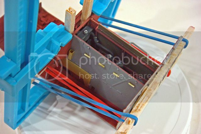
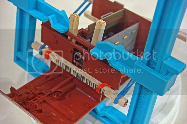
Another issue with the kit is that the main hull parts are very (VERY!) thin. I haven't actually measured them, but I'd guess that most are in the .020-.025 range. This adds to the challenge of clamping these parts together since it's very easy to distort their shapes and induce warpage into the sub-assemblies.
So, I used some balsa wood strips to spread the force equally and rubber bands for the clamping tension. I also found it was necessary to clamp the firewall to the floor to introduce some additional rigidity to the whole effort.
Oh well... I had hoped to be able to show the final engine compartment glue-up today, but I guess the grand unveiling will have to wait until tomorrow after everything has set-up and dried.
Patience, patience, patience...
Happy modeling!
Oh, wait a minute... What are we talking about?! You and me, we are a couple of those rats!
I won't tell if you won't...
In regards to the suspension. We'll see, won't we? It looks like it should go together pretty well, and if the fit of the parts that I've constructed so far is any indication, I think it's gonna be very nice indeed.
@ Jerry: As always, brother! Safe travels.
So, on to the build...
My next task has been to finish the engine compartment side walls so that I can close up the compartment and move along.
There are several PE parts that go onto the outsides of each side wall. The maintenance doors have a pair of finger lifts (four on each side, Pb 36) that must be formed and glued on.
The instructions would have you do this steps 20 and 21. Back in step 19, there's a PE ledge (Pa 7) for the radio operator's seat that's added to the right hand side wall, and back again in step 21, there's a PE holder (Pb 26) for some sort of small cleaning brush (J10). There are also PE side panels added to each side wall (Pb 21 and 14) that are added in step 16.
I decided to add all of these parts at once before adding the side walls to the engine compartment. I believe that this will make assembly and painting easier.
Here're the side walls with these parts added:

Next up was painting and weathering the interiors of these walls. I had already shot their insides with primer red, but I wanted some contrasts and visual interests, so I masked and painted the interiors of the inspection / maintenance doors the basic exterior color, G3 Green.
I used Mike Starmer's Tamiya paint mix formulas for this color. After I shot the basic color, for scale lighting and a little post-shading, I lightened the G3 with Tamiya Dark Yellow.

The interior side walls were then weathered using the same colors and steps as for the fire wall, rear hull wall, and floor.

In between waiting for painting steps to dry, I worked on the battery tray and its mounts. The instructions have you build the entire assembly and install it in step 13. The front of the battery tray is supported by a PE ledge (Pa4) that mounts to three small pins on the bottom left rear of the firewall which isn't installed until step 17. In the meantime, the batteries and their tray are supported by two small styrene feet (E4 and E5).
I thought assembly would be easier if I changed this sequence and installed the PE ledge to the firewall now, added the styrene feet to the bottom of the tray and then dry-fir the battery assembly to the floor and firewall until the feet dried. I can then remove and paint the battery assembly and install it later.
Here's the PE ledge glued to the firewall:

With the lower hull side walls installed per the instructions, and the oil cooler air conduit (rear overhang) on the firewall, and the battery tray already gled to the floor, I just don't see how this would be very practical to assemble this as suggested by Riich.
Here are a couple of views of the battery tray with the support feet glued to it, dry-fitted to the floor and firewall. I left the battery tray here until the glue on the feet had set.


Note that the wooden battery cover and its hold down screws can be removed for painting later.
Finally, I was ready to assemble the engine compartment side walls and the hull rear.
Fitting the side walls while fishing the fuel lines under their back corners and attaching the fuel line to the carburetor was a challenge like building a house of cards. Getting these parts fit together and aligned with the hull floor and firewall took quite a bit of patience.
As I noted earlier, the fit of the kit parts is so precise that a layer of paint will interfere with the fit. In this case, I did scrape as much paint away as I felt that I could without risking the need to touch up any spots INSIDE the engine compartment. This meant that I did create some fit issues. These were self-inflicted and I think that without any paint on these parts, they would have fit perfectly (as they did during the many dry-fits and test-fits).
What all this added up to was the need for some creative clamping while the engine compartment glue-up sets and dries.


Another issue with the kit is that the main hull parts are very (VERY!) thin. I haven't actually measured them, but I'd guess that most are in the .020-.025 range. This adds to the challenge of clamping these parts together since it's very easy to distort their shapes and induce warpage into the sub-assemblies.
So, I used some balsa wood strips to spread the force equally and rubber bands for the clamping tension. I also found it was necessary to clamp the firewall to the floor to introduce some additional rigidity to the whole effort.
Oh well... I had hoped to be able to show the final engine compartment glue-up today, but I guess the grand unveiling will have to wait until tomorrow after everything has set-up and dried.
Patience, patience, patience...
Happy modeling!
Big-John
Joined: August 12, 2010
KitMaker: 731 posts
Armorama: 711 posts

Posted: Saturday, August 17, 2013 - 01:41 PM UTC
Hi mike,
That sure is great craftsmanship there! Its ashamed that lil Flat Head Ford is all covered now.
That sure is great craftsmanship there! Its ashamed that lil Flat Head Ford is all covered now.

AlanL

Joined: August 12, 2005
KitMaker: 14,499 posts
Armorama: 11,675 posts
Posted: Saturday, August 17, 2013 - 09:46 PM UTC
Hi Mike,
More great progress.
Al
More great progress.
Al
SdAufKla
Joined: May 07, 2010
KitMaker: 2,238 posts
Armorama: 2,158 posts
Posted: Sunday, August 18, 2013 - 11:45 AM UTC
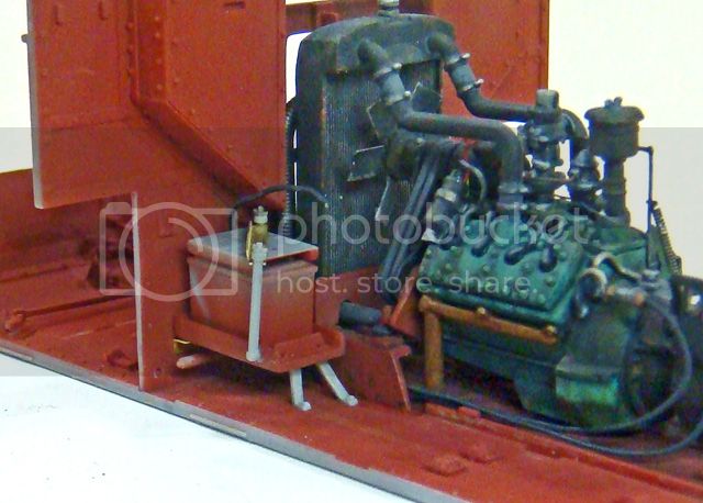
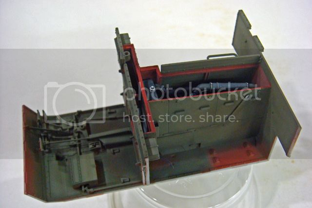
Not a whole lot of photogenic progress today.
But here are a couple of pics of the finished engine and compartment:
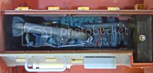
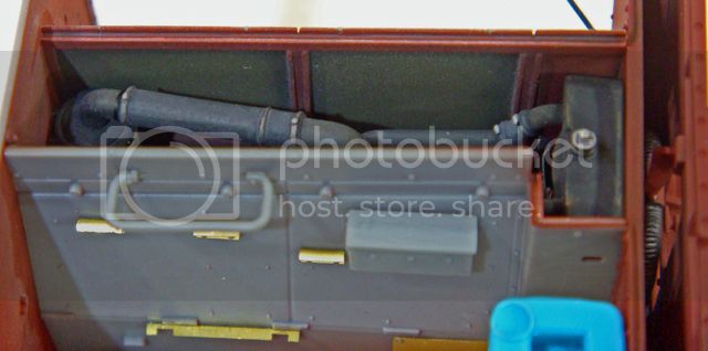
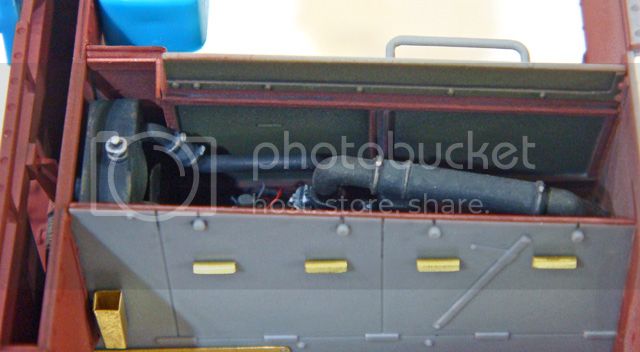
@ Big John: Yea, I hated to close it in, but I think that there will be some other nice details to check out in addition to the engine, so hopefully it'll be visible enough to see what it is and appreciate the mechanical and technical aspects.
@ Alan: Thanks! More to follow...
My plan for the next "phase" of the build is to complete the lower hull sides and the tops of the fenders. Using the same rational as for the side walls of the engine compartment, I believe that it will be both easier to build and finish these separately.
I've already test fit / dry-fit the lower hull sides along with the fenders, and as with just about everything else on this kit, they fit perfect.
I do intend to apply my lessons learned about the interference of the paint with the fit, so I'll take more time masking these parts before I paint them. Before I do paint them, I will also mask the openings in the engine compartment and paint the interior.
I'll also add the gas tanks and batteries before I add the lower hull sides.
Somewhere along this process, I'll start on the gunner and radio operator figures. I already believe that the gunner is going to need his legs reposed, and if that's the case, I think his right foot will be planted on his seat cushion. If that turns out to be the case, I'll have to modify the gunner's seat before I install it in the front compartment. Since I want to install the finished front seats before I add the lower hull side walls, fitting the gunner may take precedence over some of above construction and finishing plans.
Still, getting the engine, engine compartment and hull floor assembled has been a major step forward.
Happy modeling!
But here are a couple of pics of the finished engine and compartment:


@ Big John: Yea, I hated to close it in, but I think that there will be some other nice details to check out in addition to the engine, so hopefully it'll be visible enough to see what it is and appreciate the mechanical and technical aspects.
@ Alan: Thanks! More to follow...
My plan for the next "phase" of the build is to complete the lower hull sides and the tops of the fenders. Using the same rational as for the side walls of the engine compartment, I believe that it will be both easier to build and finish these separately.
I've already test fit / dry-fit the lower hull sides along with the fenders, and as with just about everything else on this kit, they fit perfect.
I do intend to apply my lessons learned about the interference of the paint with the fit, so I'll take more time masking these parts before I paint them. Before I do paint them, I will also mask the openings in the engine compartment and paint the interior.
I'll also add the gas tanks and batteries before I add the lower hull sides.
Somewhere along this process, I'll start on the gunner and radio operator figures. I already believe that the gunner is going to need his legs reposed, and if that's the case, I think his right foot will be planted on his seat cushion. If that turns out to be the case, I'll have to modify the gunner's seat before I install it in the front compartment. Since I want to install the finished front seats before I add the lower hull side walls, fitting the gunner may take precedence over some of above construction and finishing plans.
Still, getting the engine, engine compartment and hull floor assembled has been a major step forward.
Happy modeling!
SdAufKla
Joined: May 07, 2010
KitMaker: 2,238 posts
Armorama: 2,158 posts
Posted: Tuesday, August 20, 2013 - 01:10 PM UTC
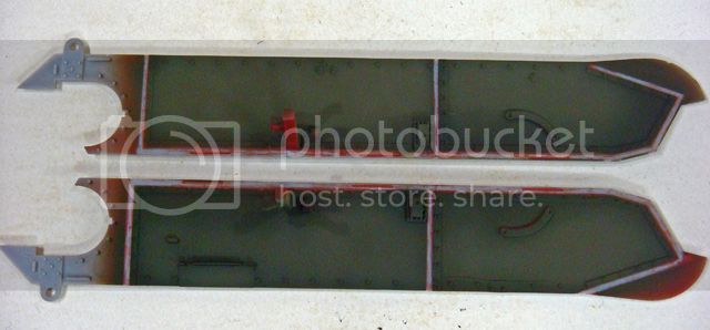
Ok, progress so far has been according to plan. I've finished adding the lower hull side interior and fender top details, masked all of the glue joints and masked the finished engine compartment.
For masking, I mostly used thin strips of ordinary blue painter's tape cut with a straight edge and an X-acto knife on a piece of glass. To mask the engine compartment, I did cut a paper masks for the top and radiator openings and used a liquid masking agent along their edges.
The following photos show the basic airbrush work - G3 Dark Green followed by some highlights of the G3 lightened with Tamiya Dark Yellow.
In the final pictures, you can see the start of the next step which is detail painting - mostly bare metal parts and chipping for wear and tear. Once I've done the entire interior, I'll start weathering with washes and glazes.
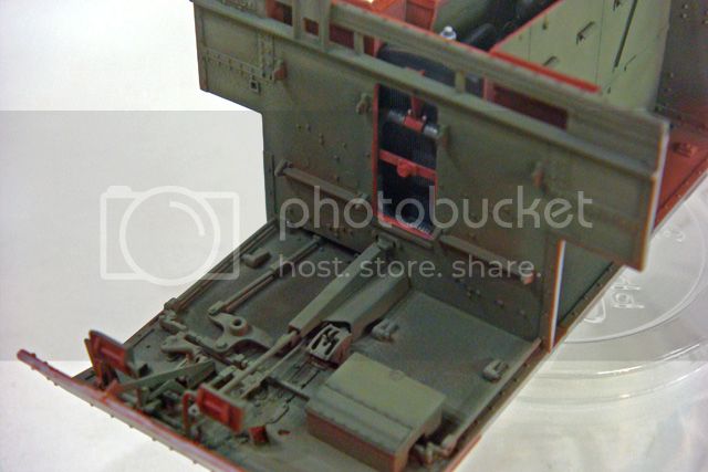
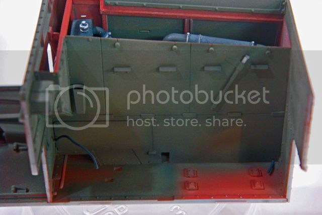
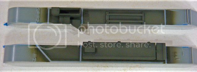
I know that some of these details, like the batteries, won't be seen, but painting them gave me a little practice and warm up the more visible stuff. It also allowed me to play around with colors to see how things would look on other areas.
For masking, I mostly used thin strips of ordinary blue painter's tape cut with a straight edge and an X-acto knife on a piece of glass. To mask the engine compartment, I did cut a paper masks for the top and radiator openings and used a liquid masking agent along their edges.
The following photos show the basic airbrush work - G3 Dark Green followed by some highlights of the G3 lightened with Tamiya Dark Yellow.
In the final pictures, you can see the start of the next step which is detail painting - mostly bare metal parts and chipping for wear and tear. Once I've done the entire interior, I'll start weathering with washes and glazes.


I know that some of these details, like the batteries, won't be seen, but painting them gave me a little practice and warm up the more visible stuff. It also allowed me to play around with colors to see how things would look on other areas.
SdAufKla
Joined: May 07, 2010
KitMaker: 2,238 posts
Armorama: 2,158 posts
Posted: Tuesday, August 20, 2013 - 01:21 PM UTC
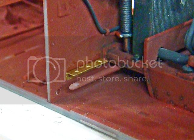
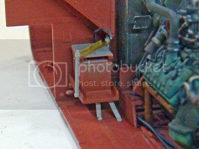
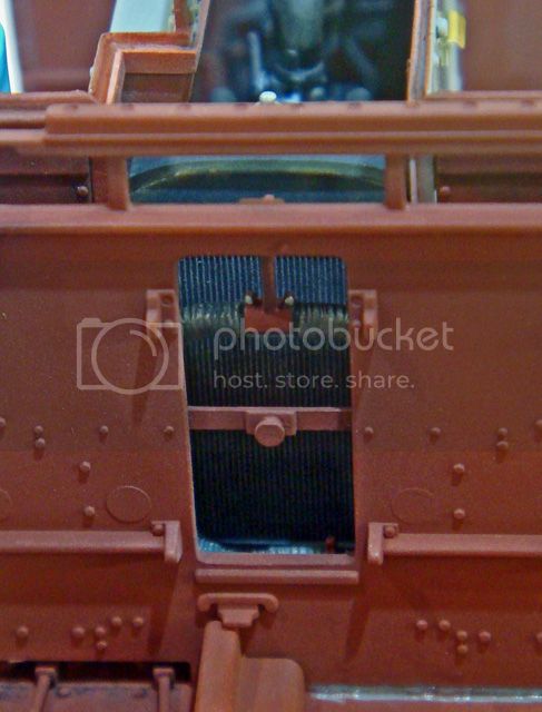
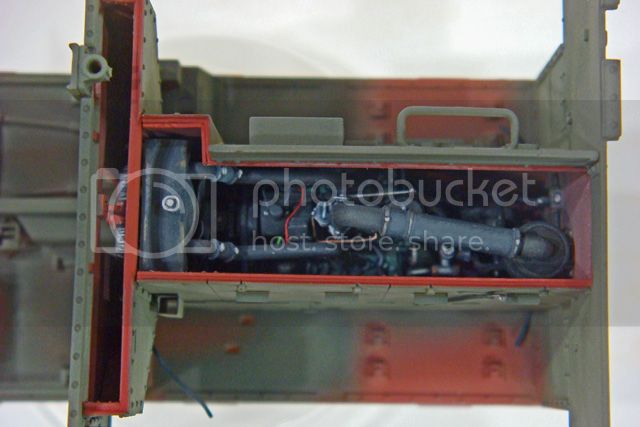
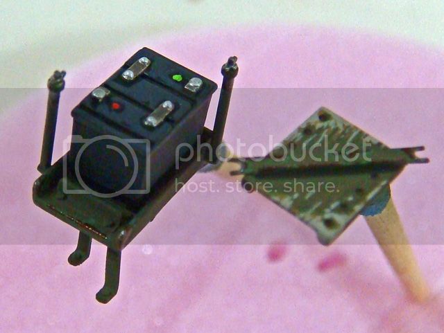
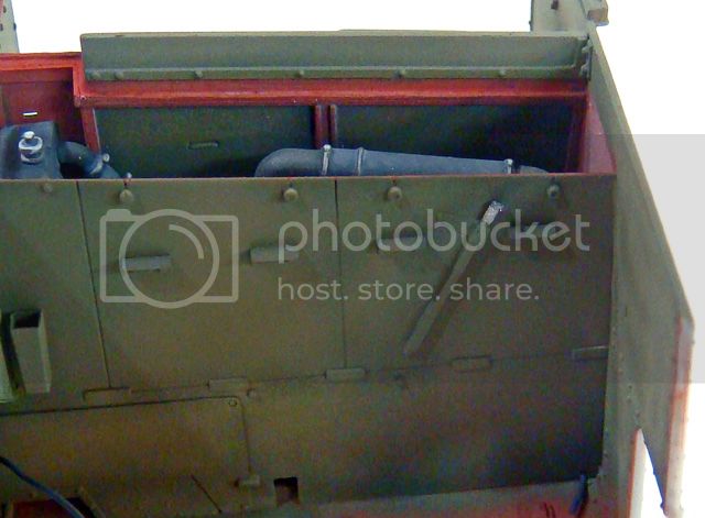
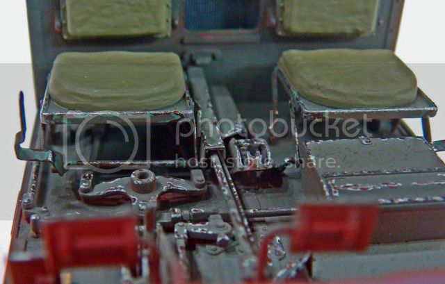
As I was looking over the kit parts, I noticed a detail on the left / port side of the engine compartment wall.
The detail is cast fairly shallow, and I couldn't quite figure out what it was. At first glance, it looks like a lever of some sort. But since it's on a removable engine maintenance cover, it doesn't make sense that it's some sort of control.
I then suspected it was a tool of some sort, maybe part of the vehicle's maintenance kit (give it's location). At any rate, on another forum, I posted this picture of the detail and asked if any one knew what it was and could they provide a photo of the prototype part.
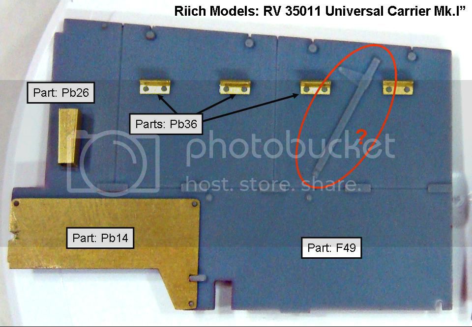
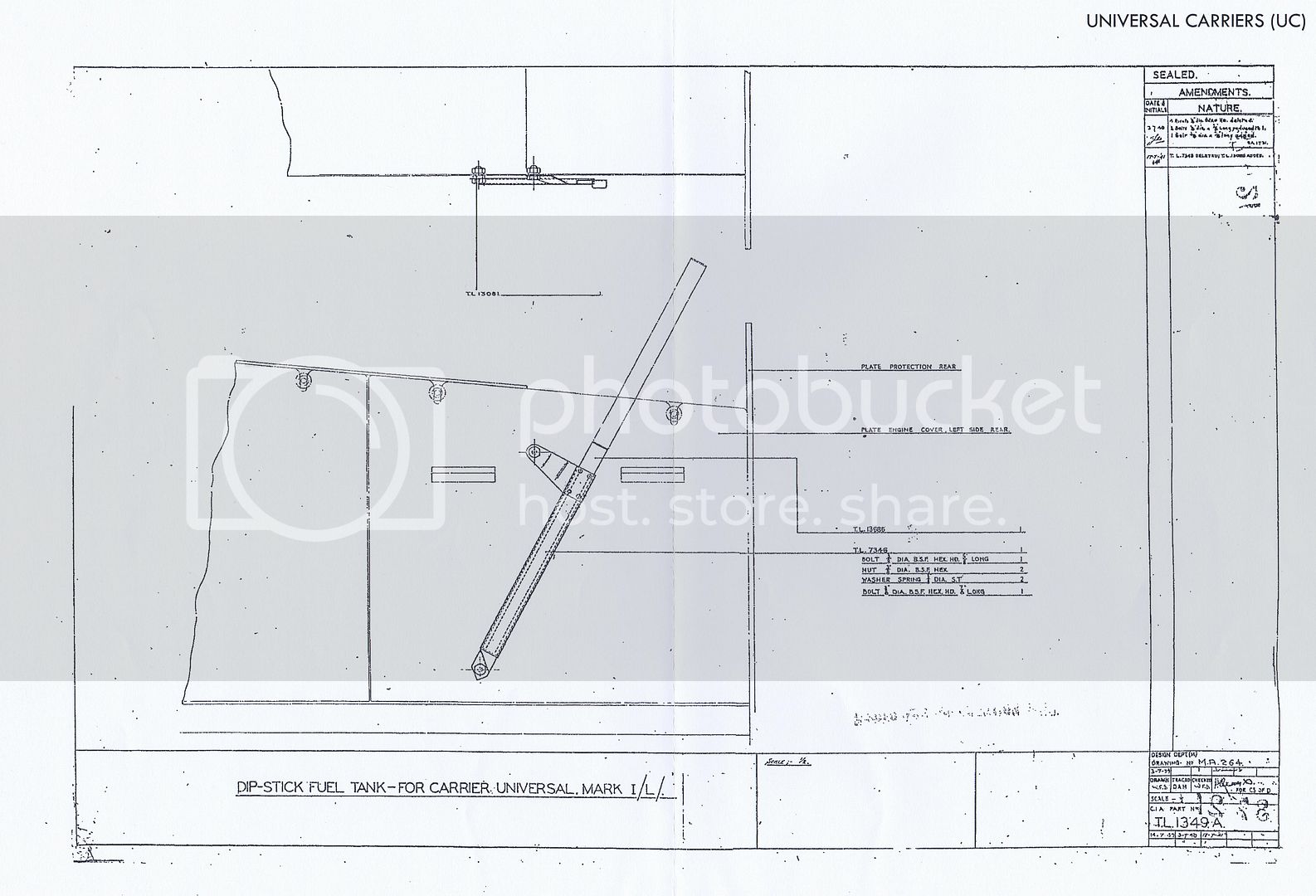
Several folks responded, and the detail was identified as a dip stick for the fuel tanks.
Ron Volstad contacted me off-line and sent me this copy of the factory drawings of the parts.
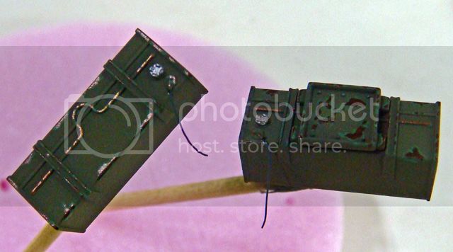
Armed with this information, I set about improving the kit details. I used strips of .005 styrene and small bit of left over PE fret and constructed my own fuel tank dip stick and stowage bracket.
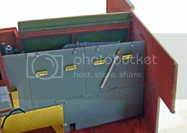
Because the .005 styrene is so thin, I actually used CA glue to put the new bracket together (so the thin styrene wouldn't melt). The new detail only took a little while to make, and it has much more depth and dimension along with a nice shadow line.
I think the extra work was worth it since by leaving the engine compartment open, I'm inviting folks to give this are a close inspection. Also, by doing a little extra research and finding out what the detail actually was, I now know how to paint and finish it.
Happy modeling!
The detail is cast fairly shallow, and I couldn't quite figure out what it was. At first glance, it looks like a lever of some sort. But since it's on a removable engine maintenance cover, it doesn't make sense that it's some sort of control.
I then suspected it was a tool of some sort, maybe part of the vehicle's maintenance kit (give it's location). At any rate, on another forum, I posted this picture of the detail and asked if any one knew what it was and could they provide a photo of the prototype part.

Several folks responded, and the detail was identified as a dip stick for the fuel tanks.
Ron Volstad contacted me off-line and sent me this copy of the factory drawings of the parts.

Armed with this information, I set about improving the kit details. I used strips of .005 styrene and small bit of left over PE fret and constructed my own fuel tank dip stick and stowage bracket.


Because the .005 styrene is so thin, I actually used CA glue to put the new bracket together (so the thin styrene wouldn't melt). The new detail only took a little while to make, and it has much more depth and dimension along with a nice shadow line.
I think the extra work was worth it since by leaving the engine compartment open, I'm inviting folks to give this are a close inspection. Also, by doing a little extra research and finding out what the detail actually was, I now know how to paint and finish it.
Happy modeling!
SdAufKla
Joined: May 07, 2010
KitMaker: 2,238 posts
Armorama: 2,158 posts
Posted: Wednesday, August 21, 2013 - 01:03 PM UTC
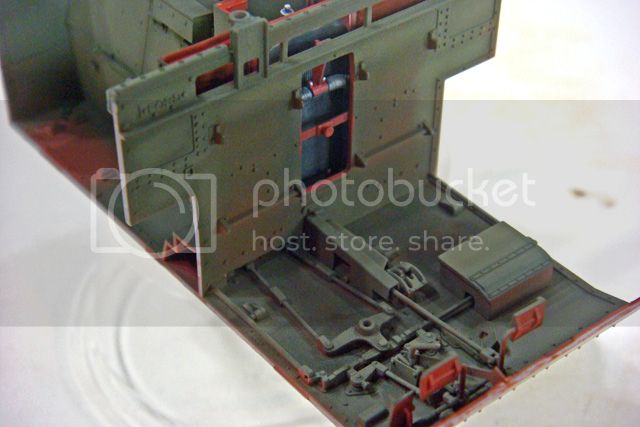
OK today's progress was mostly interior detail painting and some assembly.
The detail painting has been generally wear and tear type stuff - scuffing and chipping. I have installed the batteries and the fuel tanks in their permanent locations.
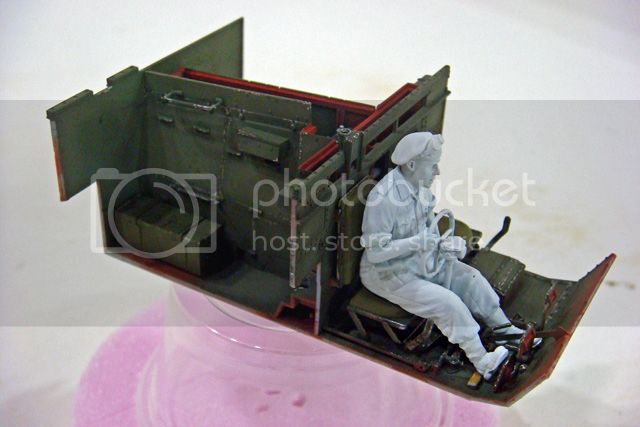
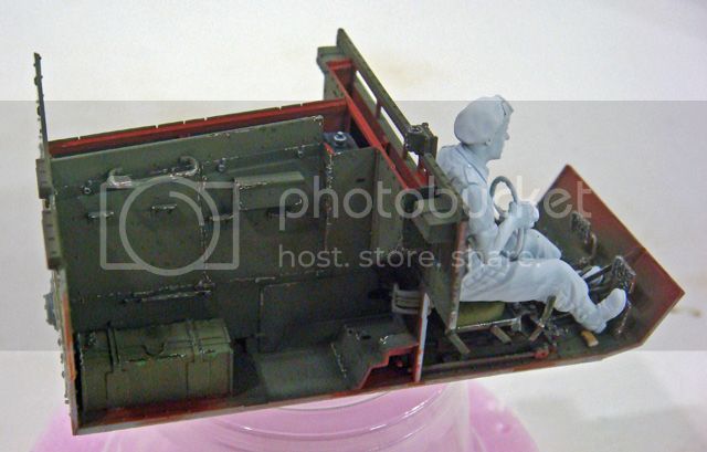
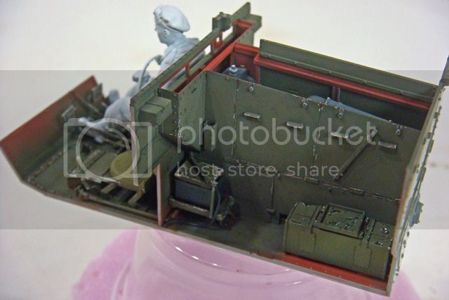
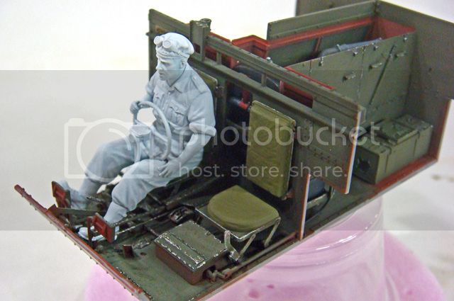
I still have some detail painting like the upholstery tacks on the seat back cushions (also for the radio operator - not shown here), but the next major step will be washes - pin washes and general washes - along with some rain and fuel / oil streaks. This will be followed by a dust glaze and then finally a coat of Testor's Dull Coat.
This is basically the same process that I used with the engine and engine compartment. Right now, the scuffing and chipping looks very stark and "contrasty," but the next weathering steps will tone it down some and and create consistency.
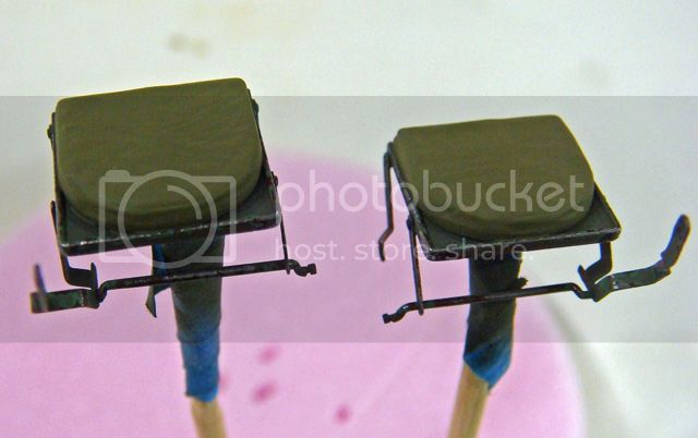
The last four extreme close-ups of the front seats are for anyone trying to figure out how they are assembled. I believe that I have mine correct, but that's not due to any help from the kit instructions which are very deficient in this area. In particular, note how the inner end of the front cross bar on each seat rests on the outside "ears" on the shifter cover. On the driver's seat, this bar has to be slid under the outside edge of the linkage tunnel, too. It's all very fiddly, but can be done.
I don't know how you're supposed to build these if the lower hull sides are in place. It's hard enough to get the floor attachments right when you can see them from the sides, but if the lower walls are in place, the seat cushions and walls block your vision.
I'll also start work on the gunner and radio operator now that I have enough of the vehicle assembled to test their fit and poses.
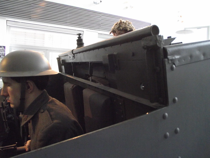
Finally, before I close for today - Does anyone know what the top rails on the Mk. I carrier are made of? I've read two different sources that say two different things. One says that they're made of wood and the other says they're made of rubber. I guess it could have been that both materials were used, but can anyone provide a definite answer?
TIA and happy modeling!
The detail painting has been generally wear and tear type stuff - scuffing and chipping. I have installed the batteries and the fuel tanks in their permanent locations.


I still have some detail painting like the upholstery tacks on the seat back cushions (also for the radio operator - not shown here), but the next major step will be washes - pin washes and general washes - along with some rain and fuel / oil streaks. This will be followed by a dust glaze and then finally a coat of Testor's Dull Coat.
This is basically the same process that I used with the engine and engine compartment. Right now, the scuffing and chipping looks very stark and "contrasty," but the next weathering steps will tone it down some and and create consistency.
The last four extreme close-ups of the front seats are for anyone trying to figure out how they are assembled. I believe that I have mine correct, but that's not due to any help from the kit instructions which are very deficient in this area. In particular, note how the inner end of the front cross bar on each seat rests on the outside "ears" on the shifter cover. On the driver's seat, this bar has to be slid under the outside edge of the linkage tunnel, too. It's all very fiddly, but can be done.
I don't know how you're supposed to build these if the lower hull sides are in place. It's hard enough to get the floor attachments right when you can see them from the sides, but if the lower walls are in place, the seat cushions and walls block your vision.
I'll also start work on the gunner and radio operator now that I have enough of the vehicle assembled to test their fit and poses.
Finally, before I close for today - Does anyone know what the top rails on the Mk. I carrier are made of? I've read two different sources that say two different things. One says that they're made of wood and the other says they're made of rubber. I guess it could have been that both materials were used, but can anyone provide a definite answer?
TIA and happy modeling!
pseudorealityx
Joined: January 31, 2010
KitMaker: 2,191 posts
Armorama: 1,814 posts
Posted: Wednesday, August 21, 2013 - 01:59 PM UTC
Looking great as usual. I'm interested to see how the next weathering phases tone down the chipping, because the high contrast does look a bit out of place right now.
The Brits weren't much for ergonomics with that thing... what's with that steering wheel location?
The Brits weren't much for ergonomics with that thing... what's with that steering wheel location?
Dangeroo

#023

Joined: March 13, 2009
KitMaker: 2,058 posts
Armorama: 1,656 posts

Posted: Wednesday, August 21, 2013 - 06:28 PM UTC
Great Progress! I especially like the way the cusions turned out!
Cheers!
Stefan
Cheers!
Stefan

Keef1648
Joined: January 23, 2008
KitMaker: 1,240 posts
Armorama: 1,192 posts

Posted: Wednesday, August 21, 2013 - 11:36 PM UTC
You could shortcut the chipping process and leave it all shiny, then remark it as a vehicle belonging to the Guards, they liked things to nice and shiny (even chipping, wear and tear)...
Just joking Mike. Lovely work thus far and I agree (strangely) it must be nigh on impossible to assemble and attach the seat parts correctly if the walls were already in place? Obviously a look ahead of the assembly and instructions proved to be the smart thing to do here.
Many following this build, with the intent of building their own will benefit greatly from this.
No doubt you are sharpening your scalpels in readiness for some more operational adjustments of the remaining figures!
Keith.
AlanL
Joined: August 12, 2005
KitMaker: 14,499 posts
Armorama: 11,675 posts
Posted: Thursday, August 22, 2013 - 12:38 AM UTC
Hi Mike,
Things are looking excellent.
Al
Things are looking excellent.
Al
exer

Joined: November 27, 2004
KitMaker: 6,048 posts
Armorama: 4,619 posts

Posted: Thursday, August 22, 2013 - 02:11 AM UTC
Amazing work
This I think a Mk 1 and the rails look to be made from mild steel spot welded in place
Here is the complete album
Quoted Text
Finally, before I close for today - Does anyone know what the top rails on the Mk. I carrier are made of? I've read two different sources that say two different things. One says that they're made of wood and the other says they're made of rubber. I guess it could have been that both materials were used, but can anyone provide a definite answer?
TIA and happy modeling!
This I think a Mk 1 and the rails look to be made from mild steel spot welded in place
Here is the complete album

SdAufKla
Joined: May 07, 2010
KitMaker: 2,238 posts
Armorama: 2,158 posts
Posted: Thursday, August 22, 2013 - 03:08 AM UTC
Good morning, guys.
@ Jesse: In regards to the ergonomics - the Universal Carrier is insane. So much machine with so little usable space, and that space is so poorly laid out for the crew one wonders what the designers were thinking.
Still, thousands were made, deployed and employed making it one of the more historically significant AFVs on the Allied side. I'm glad Riich has done such a nice job on the kit, itself.
The chipping and scuffing looks highly contrasting now, but that's all part of the plan. Maybe a little explanation of my intent and approach would be appropriate.
I'm trying to accomplish several things here at the same time. Obviously, replicating wear and tear is one of them. I have tried to keep the damaged paint to logical locations, places where the crew would routinely handle parts, fasten and unfasten things, performing maintenance, etc. Also, several grown men wearing hob-nailed brogans climbing in, out, over and around (especially stomping all over the floor are of the front compartment) would seem to cause damage to the edges and corners of all of the parts they're scraping with their boots.
However, the effect can also be used, IMO, to highlight and emphasize details and overcome the effects of scale lighting. Much the same way as dry brushing can be used to create highlights, I look at selective chipping being a useful technique to achieve the same result. And just like with dry brushing, the effect can also be incorporated into the weathering.
For this reason and to work with the other weathering techniques that I like to use, the chipping has to start off with more contrast than will be visible in the final results.
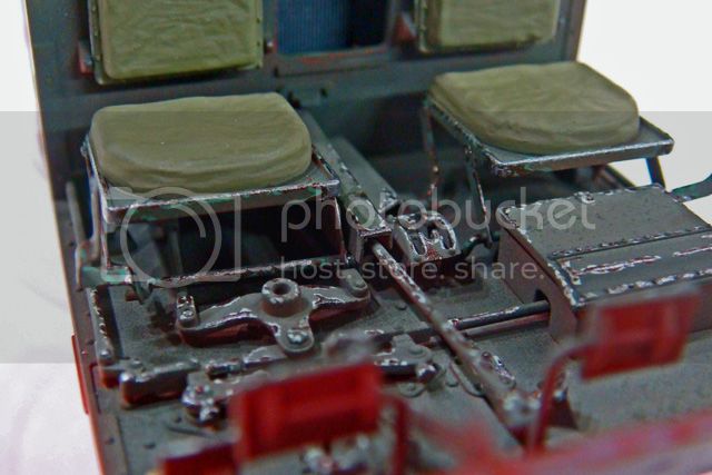
Right now the chipping contrasts strongly with the dark green base color (which has also been pre-shaded with the airbrush). If you look very closely at the front seat frames, will will see traces of the first color I experimented with for the chipping - a medium "leafy" green around the edges of some of the chips (see the last two photos, especially). I didn't think that this color actually had enough contrast, so after the initial work, I switched to an even lighter "pastel" green for the chip edge color.
At normal viewing distances, the first color did not have enough contrast to be seen. However, since one of the purposes is to emphasize some of the details (where it's logical), contrast is necessary. In fact, it is the contrast which creates the emphasis.
A couple of other things to keep in mind as you look at the photos at this stage - The photos are highly enlarged. The actual areas illustrated are very small much more difficult to see than the photos might suggest. Also, the metallic colors used - mostly Citadel "Tin Bitz" and "Bolt Gun" - are still very reflective and "glittery" at this point. This makes the light reflection in the photos stand out starkly. The majority of these chips are actually "Tin Bitz" which is a dark metallic brown with under-tones of bronze and silver. When it's coated with Dull Coat, it will almost disappear against the dark green base color. Then the "pastel" green chip "edges" will help it stand out just a little. With a dust glaze of Tamiya Buff over it first, the chip will blend in even more.
Without starting with high contrast, these later layers of weathering would make the chipping effort (remember, which is also intended to emphasize some details) completely disappear.
Anyways, that's the plan! We'll see how it works in the end.
@ Stephan: Thanks. I have used ball grinders on the kit molded cushions to give them some folds and creases and make their forms look more natural and candid. So far, the painting has just been the acrylic under coats - here Vallejo "Russian Uniform Green." Later, I will use artist oils to paint the fabric portions of the cushions (at the same time as I paint the figures) to give them more shadows and highlights.
I hope you still like them then!
@ Keith: Oh yea, this whole build is like a Science Fair project! Lot's of experimenting. Dr. Frankenstein's lab will be up and running again for the radio operator and gunner.
Seriously, though, I do hope others will find this useful with their own carrier builds.
@ Alan: Thanks again. I appreciate your interest in the project.
@ Pat: Thanks for your kind words.
Also, thanks for the link to the photo album. I appreciate time and effort to help me out.
The rails shown on that carrier are the later, Mk. II type rails, made either from steel pipe or folded sheet metal. Some Mk. II carriers have a combination of both kinds (pipe and folded) and some only one or the other.
A lot of the earlier Mk. I carriers were reworked and brought up to the Mk. II standards, which included the later metal rails.
However, the initial Mk. I rails are square or rectangular in cross-section (see the kit photos above) and according to my - conflicting! - references, these rails were either made of wood or rubber. (Perhaps both were used at different times or by different factories.)
In so far as I'm concerned, the difference determines how I will paint and weather the rails on my kit. Back to the whole chipping and scuffing discussion - if rubber, then underlying dark gray chips would seem appropriate and perhaps more of them as the flexible rubber would tend, I should think, to shed paint more easily than wood. However, if they were wooded, then more restrained chipping, but the underlying colors would be light browns and tans.
Thanks again, everybody, for the interest and comments!
Happy modeling!
@ Jesse: In regards to the ergonomics - the Universal Carrier is insane. So much machine with so little usable space, and that space is so poorly laid out for the crew one wonders what the designers were thinking.
Still, thousands were made, deployed and employed making it one of the more historically significant AFVs on the Allied side. I'm glad Riich has done such a nice job on the kit, itself.
The chipping and scuffing looks highly contrasting now, but that's all part of the plan. Maybe a little explanation of my intent and approach would be appropriate.
I'm trying to accomplish several things here at the same time. Obviously, replicating wear and tear is one of them. I have tried to keep the damaged paint to logical locations, places where the crew would routinely handle parts, fasten and unfasten things, performing maintenance, etc. Also, several grown men wearing hob-nailed brogans climbing in, out, over and around (especially stomping all over the floor are of the front compartment) would seem to cause damage to the edges and corners of all of the parts they're scraping with their boots.
However, the effect can also be used, IMO, to highlight and emphasize details and overcome the effects of scale lighting. Much the same way as dry brushing can be used to create highlights, I look at selective chipping being a useful technique to achieve the same result. And just like with dry brushing, the effect can also be incorporated into the weathering.
For this reason and to work with the other weathering techniques that I like to use, the chipping has to start off with more contrast than will be visible in the final results.
Right now the chipping contrasts strongly with the dark green base color (which has also been pre-shaded with the airbrush). If you look very closely at the front seat frames, will will see traces of the first color I experimented with for the chipping - a medium "leafy" green around the edges of some of the chips (see the last two photos, especially). I didn't think that this color actually had enough contrast, so after the initial work, I switched to an even lighter "pastel" green for the chip edge color.
At normal viewing distances, the first color did not have enough contrast to be seen. However, since one of the purposes is to emphasize some of the details (where it's logical), contrast is necessary. In fact, it is the contrast which creates the emphasis.
A couple of other things to keep in mind as you look at the photos at this stage - The photos are highly enlarged. The actual areas illustrated are very small much more difficult to see than the photos might suggest. Also, the metallic colors used - mostly Citadel "Tin Bitz" and "Bolt Gun" - are still very reflective and "glittery" at this point. This makes the light reflection in the photos stand out starkly. The majority of these chips are actually "Tin Bitz" which is a dark metallic brown with under-tones of bronze and silver. When it's coated with Dull Coat, it will almost disappear against the dark green base color. Then the "pastel" green chip "edges" will help it stand out just a little. With a dust glaze of Tamiya Buff over it first, the chip will blend in even more.
Without starting with high contrast, these later layers of weathering would make the chipping effort (remember, which is also intended to emphasize some details) completely disappear.
Anyways, that's the plan! We'll see how it works in the end.
@ Stephan: Thanks. I have used ball grinders on the kit molded cushions to give them some folds and creases and make their forms look more natural and candid. So far, the painting has just been the acrylic under coats - here Vallejo "Russian Uniform Green." Later, I will use artist oils to paint the fabric portions of the cushions (at the same time as I paint the figures) to give them more shadows and highlights.
I hope you still like them then!
@ Keith: Oh yea, this whole build is like a Science Fair project! Lot's of experimenting. Dr. Frankenstein's lab will be up and running again for the radio operator and gunner.
Seriously, though, I do hope others will find this useful with their own carrier builds.
@ Alan: Thanks again. I appreciate your interest in the project.
@ Pat: Thanks for your kind words.
Also, thanks for the link to the photo album. I appreciate time and effort to help me out.
The rails shown on that carrier are the later, Mk. II type rails, made either from steel pipe or folded sheet metal. Some Mk. II carriers have a combination of both kinds (pipe and folded) and some only one or the other.
A lot of the earlier Mk. I carriers were reworked and brought up to the Mk. II standards, which included the later metal rails.
However, the initial Mk. I rails are square or rectangular in cross-section (see the kit photos above) and according to my - conflicting! - references, these rails were either made of wood or rubber. (Perhaps both were used at different times or by different factories.)
In so far as I'm concerned, the difference determines how I will paint and weather the rails on my kit. Back to the whole chipping and scuffing discussion - if rubber, then underlying dark gray chips would seem appropriate and perhaps more of them as the flexible rubber would tend, I should think, to shed paint more easily than wood. However, if they were wooded, then more restrained chipping, but the underlying colors would be light browns and tans.
Thanks again, everybody, for the interest and comments!
Happy modeling!

SHarjacek

Joined: January 29, 2011
KitMaker: 977 posts
Armorama: 553 posts

Posted: Thursday, August 22, 2013 - 03:14 AM UTC
Amazing work on the Carrier, really enjoy reading your log!!
Kind regards.
Kind regards.
SdAufKla
Joined: May 07, 2010
KitMaker: 2,238 posts
Armorama: 2,158 posts
Posted: Thursday, August 22, 2013 - 11:21 AM UTC
@ Sven: Thanks for looking in. I'm glad you're enjoying the build!
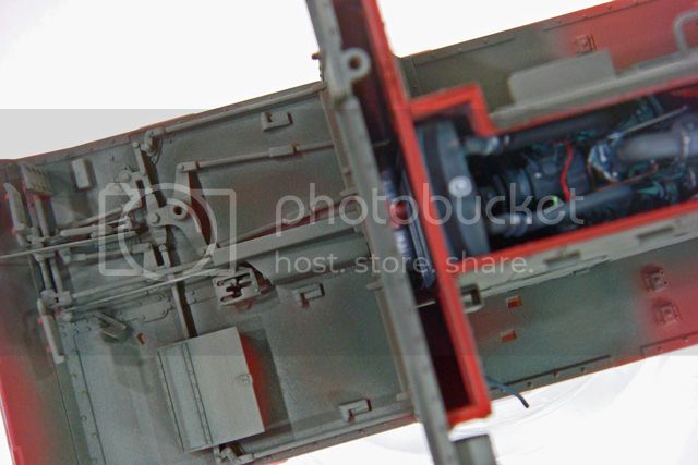
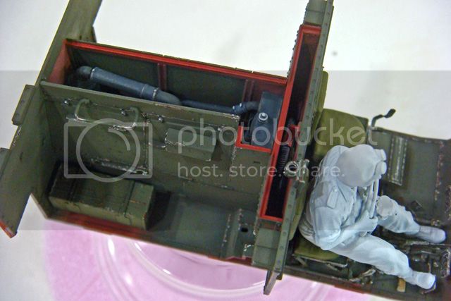
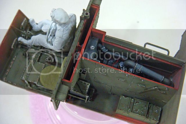
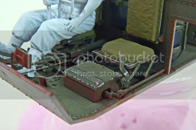
So, today, a break from painting. I installed the brake rod linkages that run through both sides of the rear compartment. These rods are absent from the kit (a strange little oversight by Riich). The forward portions are in the kit as well as the exterior brake cranks on each rear corner under the brake drums on the drive axle.
Anyways, just a couple sections of styrene rod were all that were necessary.
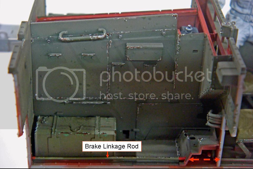
No picture of the left side since I've dry-fit the lower left hull side and fender so that I could work on posing the gunner figure.
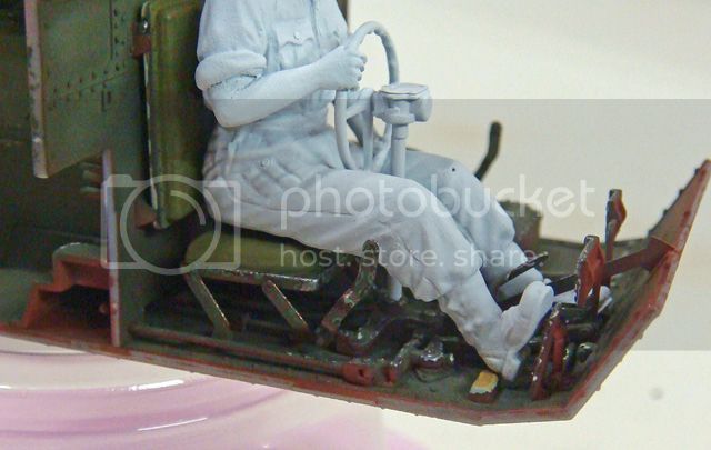
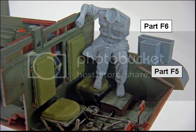
This guy is actually a lot more work than I anticipated. The kit includes a pair of open top stowage boxes, parts F5 and F6. Riich would have you add these boxes to the fender top right where the gunner is sitting. After some tests, it was obvious early on that they had to be omitted from the build since they prevent the gunner from going onto the fender.
(Also, I didn't see these boxes on too many reference pics. Either they weren't fitted to all carriers, or the crews unbolted and moved them.)
Early test fitting showed that the gunner's right leg would have to be modified, but I kind of expected (HOPED!) that the rest of the figure would fit. Unfortunately, his right arm is either sculpted too low (if the boxes are left off) or too high (if the boxes are installed).
(With the boxes installed, the gunner sits so high that his left foot actually rests on the top edge of the fender.)
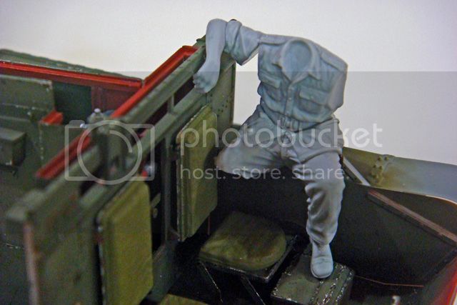
My first step was to fit the left leg and buttocks after cutting the right leg off at the knee. A bit of work to get a flat sit on the fender, and then I added the torso.
A bit of work was needed to get a good fit between the torso and lower body. While I did this, I sharpened up some of the other details, like pocket flaps, seams, etc.
I then worked on the right arm. Quite a bit of time was spent cleaning up the hand, and then after test fitting, I used a file to create a smooth area to sit on the rail on the top of the firewall. Once this joint was nice and tight, I fit the shoulder joint. This is the point where I stopped today to let the torso and shoulder joints set hard and dry.
Tomorrow, I'll reinforce the right shoulder joint and work on the right lower leg.
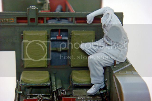
I believe that the lower leg will rest with the calf-Achilles tendon on the edge of the seat cushion. This will require posing the foot bent forward in a more relaxed attitude, shaping the rear of the leg and calf, then "crushing" the edge of the seat cushion. I'll then add back the folds and creases for the lower pants and the seat.
(Of course, this means removing the seat, adding material to the bottom, then grinding away the "crushed" edge for the leg to fit into.)
Unfortunately, I won't be able to pose the left arm until the carrier's upper front hull and glacis have been constructed, and that will have to wait until I have the upper hull sides finished (on their insides) and glued on. That will have to wait until I've built and fitted the radio and at least reposed the radio operator. (Hopefully I can add him after the carrier sides and radio are glued on. If he won't fit, I'll have to paint and install him first.)
And so it goes....
Happy modeling!
So, today, a break from painting. I installed the brake rod linkages that run through both sides of the rear compartment. These rods are absent from the kit (a strange little oversight by Riich). The forward portions are in the kit as well as the exterior brake cranks on each rear corner under the brake drums on the drive axle.
Anyways, just a couple sections of styrene rod were all that were necessary.

No picture of the left side since I've dry-fit the lower left hull side and fender so that I could work on posing the gunner figure.
This guy is actually a lot more work than I anticipated. The kit includes a pair of open top stowage boxes, parts F5 and F6. Riich would have you add these boxes to the fender top right where the gunner is sitting. After some tests, it was obvious early on that they had to be omitted from the build since they prevent the gunner from going onto the fender.
(Also, I didn't see these boxes on too many reference pics. Either they weren't fitted to all carriers, or the crews unbolted and moved them.)
Early test fitting showed that the gunner's right leg would have to be modified, but I kind of expected (HOPED!) that the rest of the figure would fit. Unfortunately, his right arm is either sculpted too low (if the boxes are left off) or too high (if the boxes are installed).
(With the boxes installed, the gunner sits so high that his left foot actually rests on the top edge of the fender.)
My first step was to fit the left leg and buttocks after cutting the right leg off at the knee. A bit of work to get a flat sit on the fender, and then I added the torso.
A bit of work was needed to get a good fit between the torso and lower body. While I did this, I sharpened up some of the other details, like pocket flaps, seams, etc.
I then worked on the right arm. Quite a bit of time was spent cleaning up the hand, and then after test fitting, I used a file to create a smooth area to sit on the rail on the top of the firewall. Once this joint was nice and tight, I fit the shoulder joint. This is the point where I stopped today to let the torso and shoulder joints set hard and dry.


Tomorrow, I'll reinforce the right shoulder joint and work on the right lower leg.
I believe that the lower leg will rest with the calf-Achilles tendon on the edge of the seat cushion. This will require posing the foot bent forward in a more relaxed attitude, shaping the rear of the leg and calf, then "crushing" the edge of the seat cushion. I'll then add back the folds and creases for the lower pants and the seat.
(Of course, this means removing the seat, adding material to the bottom, then grinding away the "crushed" edge for the leg to fit into.)
Unfortunately, I won't be able to pose the left arm until the carrier's upper front hull and glacis have been constructed, and that will have to wait until I have the upper hull sides finished (on their insides) and glued on. That will have to wait until I've built and fitted the radio and at least reposed the radio operator. (Hopefully I can add him after the carrier sides and radio are glued on. If he won't fit, I'll have to paint and install him first.)
And so it goes....
Happy modeling!

hliu24
Joined: November 19, 2010
KitMaker: 798 posts
Armorama: 797 posts
Posted: Thursday, August 22, 2013 - 12:55 PM UTC
Congrats, Mike  ...... unbelievable.
Jay
...... unbelievable. Jay
Keef1648
Joined: January 23, 2008
KitMaker: 1,240 posts
Armorama: 1,192 posts
Posted: Thursday, August 22, 2013 - 11:38 PM UTC
Great stuff Mike, more 'cut n paste' 
Keith.
Keith.
SdAufKla
Joined: May 07, 2010
KitMaker: 2,238 posts
Armorama: 2,158 posts
Posted: Friday, August 23, 2013 - 01:12 AM UTC
@ Jay: That's very kind. Hope you stick around and keep checking in on the build. There's still a LONG ways to go.
@ Keith: Bwha-ha-ha-ha... Welcome to Mike's little house of little horrors!
It's kind of funny, my poor wife (who Keith knows well) was teasing me about how horrible these poor figures look all cut apart, pieced back together and with no heads - all very "halloweeny" and "horror filmy"!
Of course, she's obligated by standing house rules to "oooh" and "ahhh" most appropriately as she's subjected to previews of all my work before I inflict it on the general public. Some humor on her part is perfectly understandable.
Now, back to the la-bore-a-tory. Bwha-ha-ha-ha...
Happy modeling!
Quoted Text
Great stuff Mike, more 'cut n paste'
Keith.
@ Keith: Bwha-ha-ha-ha... Welcome to Mike's little house of little horrors!
It's kind of funny, my poor wife (who Keith knows well) was teasing me about how horrible these poor figures look all cut apart, pieced back together and with no heads - all very "halloweeny" and "horror filmy"!
Of course, she's obligated by standing house rules to "oooh" and "ahhh" most appropriately as she's subjected to previews of all my work before I inflict it on the general public. Some humor on her part is perfectly understandable.
Now, back to the la-bore-a-tory. Bwha-ha-ha-ha...
Happy modeling!

Dannyd

Joined: March 27, 2007
KitMaker: 803 posts
Armorama: 793 posts

Posted: Friday, August 23, 2013 - 01:34 AM UTC
Hi Mike , still following this very closely, I've had to buy this kit now so I can have a crack at building one because of you :-) I'll be borrowing a few tips from your build mate. Keep it up, every time I drop by I'm blown away by the sheer quality of the work.
Regards
Dan
Regards
Dan
Keef1648
Joined: January 23, 2008
KitMaker: 1,240 posts
Armorama: 1,192 posts
Posted: Friday, August 23, 2013 - 02:07 AM UTC
Quoted Text
@ Jay: That's very kind. Hope you stick around and keep checking in on the build. There's still a LONG ways to go.Quoted TextGreat stuff Mike, more 'cut n paste'
Keith.
@ Keith: Bwha-ha-ha-ha... Welcome to Mike's little house of little horrors!
It's kind of funny, my poor wife (who Keith knows well) was teasing me about how horrible these poor figures look all cut apart, pieced back together and with no heads - all very "halloweeny" and "horror filmy"!
Of course, she's obligated by standing house rules to "oooh" and "ahhh" most appropriately as she's subjected to previews of all my work before I inflict it on the general public. Some humor on her part is perfectly understandable.
Now, back to the la-bore-a-tory. Bwha-ha-ha-ha...
Happy modeling!
Obligated my foot, I know who's the real boss in your log cabin...

Keith.
SdAufKla
Joined: May 07, 2010
KitMaker: 2,238 posts
Armorama: 2,158 posts
Posted: Saturday, August 24, 2013 - 01:18 AM UTC
@ Dan: Thanks again. It's a great little kit, and quite fun to build if you can get around the assembly sequence.
The figures, themselves, are not really too bad. They're pretty typical of current plastic figures, fair sculpting on the uniforms and so-so heads. I'd rate them very close to MiniArt in quality. If only their posing was more than just vaguely related to the actual kit, they'd rate much higher in my book.
I spent all of my last building session working on the gunner and radio operator, but not too much to show for it right now so no new pictures today. Hopefully in another couple of build sessions I'll have enough progress to justify the effort of setting up the camera, etc. That way you'll be able to better see what I'm trying to do with them.
@ Keith: Oh, I am sooo busted!
I confess all before a jury of my peers and will now do 100 up-pushes in the Peoples' Pond as penance...
After that, it's back to my Sweeny Todd impersonation and more cutting and hacking on the ol' carrier figures.
SdAufKla
Joined: May 07, 2010
KitMaker: 2,238 posts
Armorama: 2,158 posts
Posted: Monday, August 26, 2013 - 11:47 AM UTC
OK, well it's been a few days since I posted anything new, so maybe it's time to catch up.
Several areas are getting worked more or less at the same time. No need to repeat the whole explanation of how the build sequence has to be modified. It's enough to just say that all of these things have to come together during final assembly of the interior. Also, they all have to be done separately, but because they all effect each other, there's a lot of back and forth between one then another and back again...
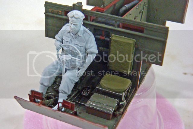
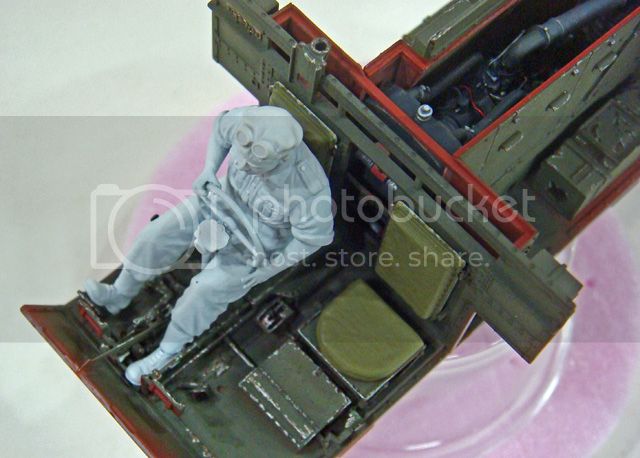
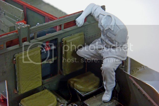
First up is the gunner. He's about done as far as I can take him until the upper hull sides and front are done, then his left arm will be posed. Exactly where it'll go, I can't say just yet (except on his left shoulder ).
After some consideration and experimentation, I settled on his right foot and boot heel resting in the right front corner of his seat. I really didn't want to have to grind the seat cushion up and re-sculpt it, and in the end, this position looked more natural than what I initially thought.
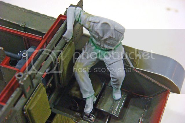
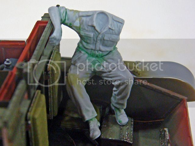
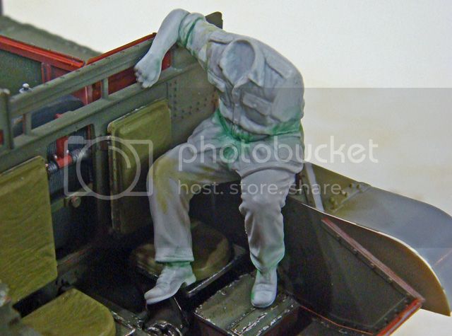
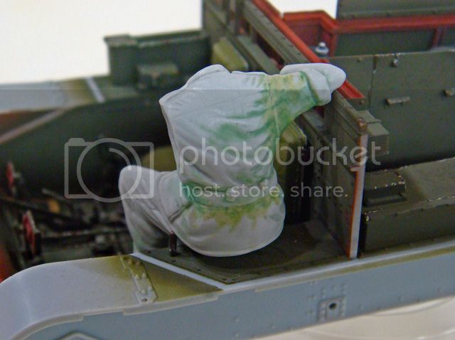
He still gets a holstered pistol on his right hip and new uniform buttons, and I'll add those by and by, but until the upper hull get's done, that's all for the gunner.
More to follow...
Several areas are getting worked more or less at the same time. No need to repeat the whole explanation of how the build sequence has to be modified. It's enough to just say that all of these things have to come together during final assembly of the interior. Also, they all have to be done separately, but because they all effect each other, there's a lot of back and forth between one then another and back again...
First up is the gunner. He's about done as far as I can take him until the upper hull sides and front are done, then his left arm will be posed. Exactly where it'll go, I can't say just yet (except on his left shoulder
).After some consideration and experimentation, I settled on his right foot and boot heel resting in the right front corner of his seat. I really didn't want to have to grind the seat cushion up and re-sculpt it, and in the end, this position looked more natural than what I initially thought.


He still gets a holstered pistol on his right hip and new uniform buttons, and I'll add those by and by, but until the upper hull get's done, that's all for the gunner.
More to follow...
Big-John
Joined: August 12, 2010
KitMaker: 731 posts
Armorama: 711 posts
Posted: Monday, August 26, 2013 - 11:52 AM UTC
Nice work on the gunner Mike. I'm glad to see the old Chap get his leg back!
Keef1648
Joined: January 23, 2008
KitMaker: 1,240 posts
Armorama: 1,192 posts
Posted: Monday, August 26, 2013 - 11:55 AM UTC
That's all! Oh I know, your off down to the second hand store for a left arm :-)
I see a new crew has been released by itslf. I wonder if they haver seen or been mated to the kit?
Great job Mike.
Keith
I see a new crew has been released by itslf. I wonder if they haver seen or been mated to the kit?
Great job Mike.
Keith
 |

WEB HOSTING BY


Copyright ©2021 Armorama and Kitmaker Network, a subsidiary of Silver Star Enterprises
All Rights Reserved. Please read our Conditions of Use and Privacy Policy.
All Rights Reserved. Please read our Conditions of Use and Privacy Policy.