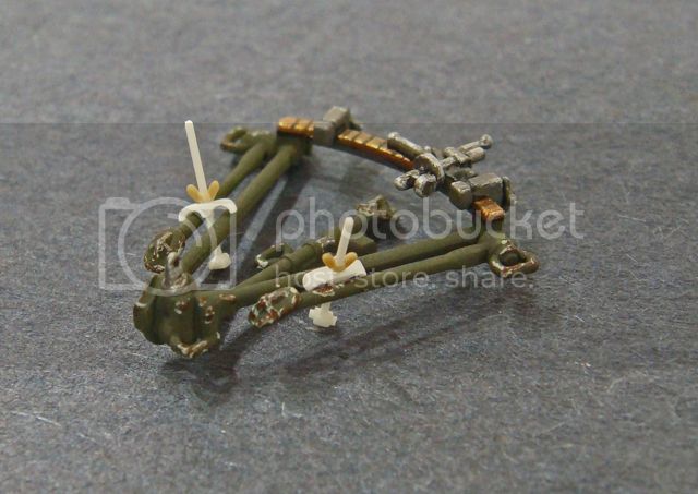
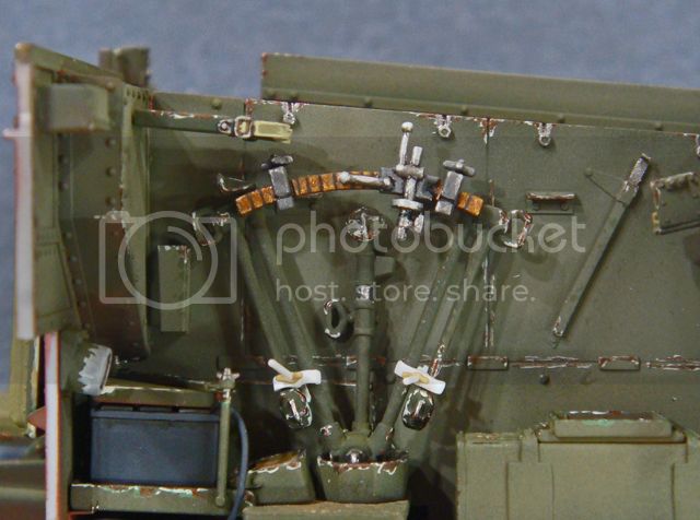
Now, on to the radio operator.
This guy is gonna be a real problem child!
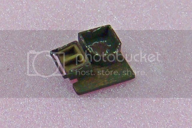
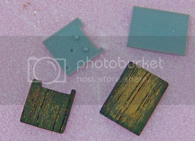
The first thing necessary was to make the duck boards that sit on the floor of the carrier. The radio operator SHOULD (!) have his feet resting on the duck board on his side of the fighting compartment.
The kit parts, F36 and F37, were fairly uninspiring, so I made replacements by laminating thin wood (used to wrap cigars) on to some .010 styrene. After painting these the base dark green color, I used some fine steel wool to rub some of the paint off and expose the wood grain.
I already had the radio operator's seat cushion, kit part B6, in initial paint, but it was so bulky that I also painted up a spare cushion B7 (intended for the radio operator's back).
(The kit has 2 B sprues, so there are doubles of both of these parts.)
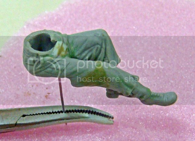
A quick test fit of the radio operator's legs showed that not only are they spread too wide to fit into the compartment, but if the B6 cushion is used, his feet cannot touch the duck board floor.
My first change was to move his knees closer together by trimming the two halves at a slight angle. This got his legs into the compartment, but the kit sculpted pose has him sitting at "attention" - very unnatural looking.
So, I pried his legs apart, move his right leg and hip down so that this knee was pointing more forward. I then cut his right knee apart and moved his lower leg to point forward. Both of his feet were cut off and the toes pointed down in a more natural position.
In order to get him to sit flat on the seat cushion, B7, I had to trim the back of his right thigh and buttock (after back filling the hollow kit parts with styrene). This looks odd in the photos below, but keep in mind that some of this in real life would be the back of his thigh "squishing" as the leg muscle relaxed. Also, the real seat cushion would "crush" under his weight. So the material I removed, in real life, would be accounted for by these two action.
Once positioned in the model, this area of his leg will be invisible to the viewer.
In this photo, you can see the reposed legs and the two seat cushions (B6 and B7) for comparison.
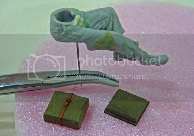
Now that I have the radio operator's legs posed, I now have to fit him and the radio together.
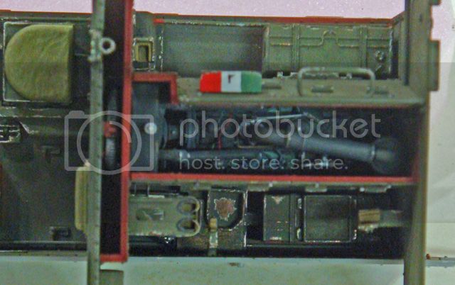
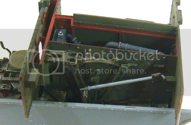
Here you can see just how little room there is for the operator and his equipment. Also, I want to use the guard on the radio, so I know now that I'll have to grind away a bit of the right hip, add the material back with two-part epoxy putty, and then re-sculpt the area to account for the bars on the guard.
I'll cover the radio stuff in the next post...
Hosted by Darren Baker
Riich Models RV35011
SdAufKla
South Carolina, United States
Joined: May 07, 2010
KitMaker: 2,238 posts
Armorama: 2,158 posts
Joined: May 07, 2010
KitMaker: 2,238 posts
Armorama: 2,158 posts
Posted: Monday, August 26, 2013 - 12:12 PM UTC
SdAufKla
South Carolina, United States
Joined: May 07, 2010
KitMaker: 2,238 posts
Armorama: 2,158 posts
Joined: May 07, 2010
KitMaker: 2,238 posts
Armorama: 2,158 posts
Posted: Monday, August 26, 2013 - 12:35 PM UTC
So, Riich gives us TWO complete radio sets for the carrier. The earlier No. 11 set and the later No. 19 set. All very nice...
However, Riich only gives us instructions to build ONE radio - the No. 11 set. Naturally, I want to build a Canadian carrier in Italy in 1943, so I need to use the No. 19 set. (Of course!)
Fortunately, the No. 19 radio set is very easy to research on-line, and I have plenty of information collected for other projects. One thing I even found were the installation instructions - Canadian! - for the Universal Carrier.
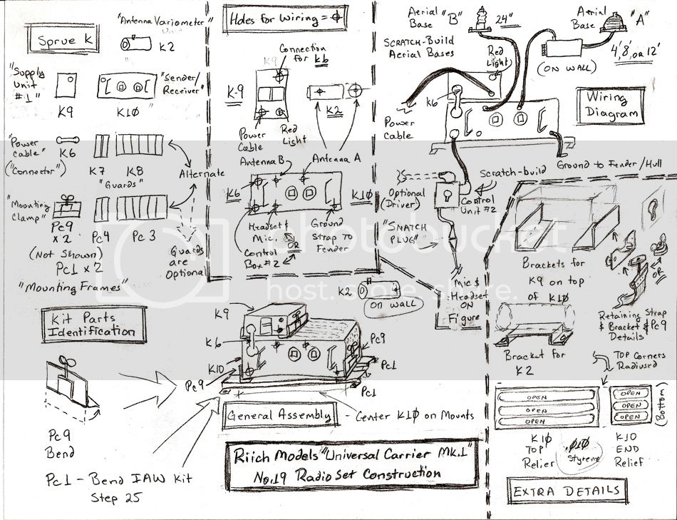
Armed with my research and some time examining the Riich parts (sprue K), I made myself some construction notes and I was ready.
Here's a cleaned up copy of my notes. I don't normally sketch them up as neat as this for myself, but I thought that someone else here might want to give this a try too. (I'll up-load a better copy of these sketches to our AMPS club's website in the next couple of weeks and post a link in this thread.)
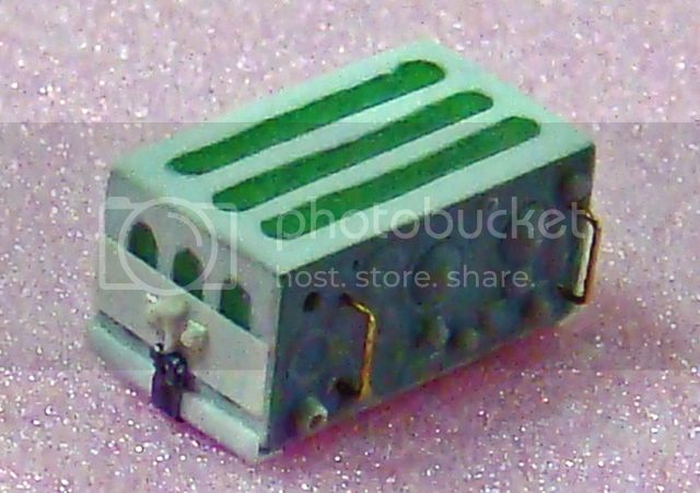
Basically, on plastic sprue K, Riich gives us the parts for the sender-receiver (K10); the supply unit no.1 (power supply / transformer K9); the connector (power cable K6), the aerial variometer (antenna matching unit K2); plastic guards (K7 and K8).
In addition to these parts, on PE fret c, Riich also gives us radio clamps (Pc9 x 2); alternate PE radio guards (Pc3 and Pc4).
My sketches show how all of this is fit together. Usually, the Supply Unit No. 1 was mounted on the left end of the Sender / Receiver, but the Canadian Universal Carrier installation instructions show it mounted on top. I found plenty of photos of No. 19 radios set-up like this, so I'm following the official instructions. (BTW:Tank and armored car radios usually have the side-by-side configuration.)
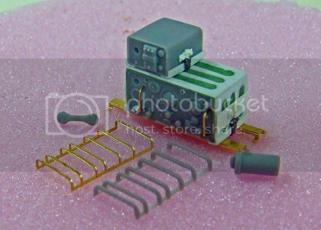
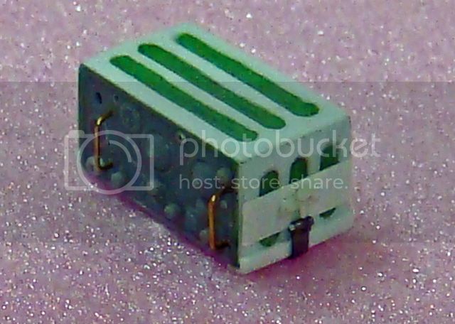
You can see the details that I've added in white styrene. A prominent feature of the No. 19 are the ribs on the top and ends, and since this radio is fully exposed, I felt this was worth the effort.
I had intended to use the kit PE parts Pc9 (radio clamps), but in the top-bottom installation configuration, you need four of them (two for the sender-receiver and two for the supply unit), so I scratched up new clamps and retainer straps.
Unfortunately, the white-on-white styrene clamp parts don't show up too well, but in future photos of the painted radio, maybe they'll show better.
Now, with the radio constructed, I can go back to the radio operator and hopefully finish reposing him.
'Til next time, happy modeling!
Posted: Monday, August 26, 2013 - 07:37 PM UTC
This is really a fantastic build log. I really like the trick with the cigar wrapper. I'll try that one day. Now off to buy some cigars...
Cheers!
Stefan
Cheers!
Stefan
SdAufKla
South Carolina, United States
Joined: May 07, 2010
KitMaker: 2,238 posts
Armorama: 2,158 posts
Joined: May 07, 2010
KitMaker: 2,238 posts
Armorama: 2,158 posts
Posted: Tuesday, August 27, 2013 - 01:08 AM UTC
@ John: Thanks, as always. The ol' gunner does look a little more human with both legs and the gaps filled in!
@ Keith: Yea, it's time to send Igor out to "dig one up"!
It's really hard to say if the Riich Models "Universal Carrier Crew in Winter Uniform 1943-1945" RV35028 fits any better or not. The box art poses look about the same as for the kit figures. Really hard to say just by looking at the box art or pictures of the isolated figures.
Still, they might be a better starting point for someone looking for a crew in temperate weight uniforms rather than tropical weight.
(By the way, Keith, we're really missing your work around here on Armorama. Your Chieftain Mk.7 ARRV conversion is going great and would make a nice blog...)
@ Stefan: Glad you're enjoying the build!
I've actually wanted to try laminating the cigar wrapper to see how it would look for quite some time, but this is the first project where I could use the technique.
I'm pretty happy with the results and can see that it has a lot of potential for some applications.
For these duck boards, I cut replacements out of .010 sheet styrene and pre-painted them in a medium brown. After that had dried over night, I used medium thickness CA glue to attache the thin wood veneer which was trimmed and sanded to size. I then painted that in the dark green base color, allowed that to dry, then buffed with the steel wool to expose the raw wood and grain.
I could easily see some nice effects with more than one base color used and buffing to reveal an even older, more worn look as if the wood had been painted several times over a period.
Happy modeling!
Posted: Tuesday, August 27, 2013 - 03:19 AM UTC
Hi Mike,
Coming along a treat, excellent work all round. As Riich provided such a detailed kit I was surprised they didn't do the engine side panels as separate items. These were just access panels that were held in place by Knurled nuts and could be easily removed for maintenance.
If modellers want to expose the engine that would be a relatively simple fix providing they remember add the interior frame.
Al
SdAufKla
South Carolina, United States
Joined: May 07, 2010
KitMaker: 2,238 posts
Armorama: 2,158 posts
Joined: May 07, 2010
KitMaker: 2,238 posts
Armorama: 2,158 posts
Posted: Wednesday, August 28, 2013 - 12:19 PM UTC
@ Al: Thanks.
Removing the engine inspection / maintenance doors on the sides of the engine compartment is certainly doable. The left side doors, especially, are just flat sheet metal panels. The right side would be a little more work since the doors have a bend about 1/5th the way down from their top edges. There's also a flange on the right side front door's front edge.
Still, it's a viable display option. Another possibility might be a maintenance type vignette or diorama. There's a great photo of the engine being lifted out of a carrier by wrecker. A small copy of the photo is on page 39 of Osprey NVG 110 "Universal Carrier." A much larger copy of the same pic is on page 24 of Guthrie & Beldam's Armour Color Gallery #5, "Camouflage & Markings of Canadian Armoured Vehicles" [DND Army 0045p].
Anyways... on to this build.
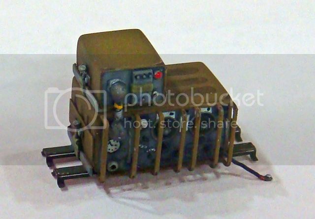
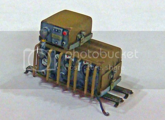
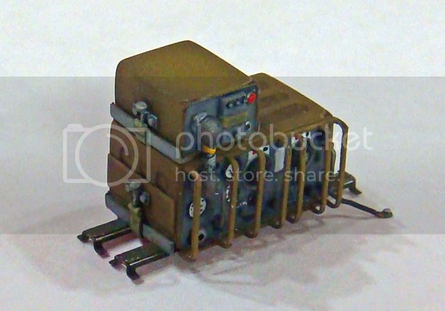
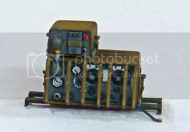
Some progress on painting and assembling the No. 19 radio set.
I've used the PE guard on the radio and will use the plastic guard as a part of a sculpting tool to press the creases into the radio operator figure.
Hopefully, the new mounting clamps show up better in these photos than they did in the last pics.
The wire sticking out from the right bottom corner of the radio is the ground wire which will be attached to the fender. The other wires will be installed as the interior goes through final assembly stages.
The radio and power supply case (as well as the variometer - not shown) are painted in the later SCC2 Brown since on my model, the No. 11 set has been replaced by the later No.19, and the whole thing, when finished, will represent a vehicle in Italy in 1943.
The radio and power supply faces (as well as the control unit No. 2 - not show - it's still under construction) are painted in a gray with white instruction plates. Other combinations are the gray with black data plates and a pale, greenish-yellow ("glow in the dark") color with black data plates. I considered the pale greenish-yellow, but didn't know when the glow in the dark paint was introduced (also, most of my reference pics show the basic gray or light gray).
I have a few other interior details on the carrier that I'm working on at the same time as the radio (while waiting for the paint to dry, etc), but I'll show those later.
For now, the radio is ready to install in the carrier once the radio operator has been painted and glued into position (the guard on the radio will prevent the operator figure from inserting after the radio).
Happy modeling!
Keef1648
South Carolina, United States
Joined: January 23, 2008
KitMaker: 1,240 posts
Armorama: 1,192 posts
Joined: January 23, 2008
KitMaker: 1,240 posts
Armorama: 1,192 posts
Posted: Wednesday, August 28, 2013 - 11:08 PM UTC
I have nothing but admiration for this 'Out of the Box' build of yours Mike.
You inspire all of us to work harder and smarter on our own items....
Research being the major key I think, before starting anything.
I hope I can log in to your build from Vegas next week, otherwise it is going to be a boring trip, yeah really (not)
But I could possibly suffer from withdrawal symptoms !
Keith.
jrutman
Pennsylvania, United States
Joined: April 10, 2011
KitMaker: 7,941 posts
Armorama: 7,934 posts
Joined: April 10, 2011
KitMaker: 7,941 posts
Armorama: 7,934 posts
Posted: Saturday, August 31, 2013 - 06:08 AM UTC
I have to keep reminding myself that this is supposed to be OOTB right?
I suppose your version of OOB is a lot different than mine? Either way,it is very enlightening for sure. Love that drivers' station and the radip is over the top nice.
J
I suppose your version of OOB is a lot different than mine? Either way,it is very enlightening for sure. Love that drivers' station and the radip is over the top nice.
J
SdAufKla
South Carolina, United States
Joined: May 07, 2010
KitMaker: 2,238 posts
Armorama: 2,158 posts
Joined: May 07, 2010
KitMaker: 2,238 posts
Armorama: 2,158 posts
Posted: Saturday, August 31, 2013 - 12:57 PM UTC
@ Keith: As always, I appreciate the comments and observations.
Enjoy your trip and remember, "What goes on in Vegas, stays in Vegas!" Well... hopefully not ALL your money!
@ Jerry: Hey old buddy, glad you're still checking in here. Thanks for the props!
Ok, now about this "out of the box" thing. You guys are killin' me!
Obviously, that was the wrong way to characterize this build. Let's just say that I don't have any plans (right now!) to use any AM accessories (except the Hornet heads and Ultracast Mk1 Tank Helmets) and leave it at that. I mean, what's a few little bits of sheet styrene and wire between friends, eh?
Any hooo...
I've come across some excellent photos of a preserved carrier in South Africa (I believe) and have been comparing the Riich kit to the real thing. It turns out that Riich has included several parts (beside the No. 19 radio!) that should probably be included in the build. There are locator holes and pins for these parts, but they're not shown on the instructions.
This wouldn't have been so bad except that I've almost finished the interior, and of course, all of these parts go into areas already painted, etc. There are also a few details that I would have like to have added (especially before I finished up with the engine and its compartment) that I now want to try to add.
So, I'll be back-tracking a little over the next few build sessions to sort these bits out. Hopefully I'll be able to show the additions and omissions soon for anyone else working on their own Riich carrier.
Happy modeling... and no, it's not REALLY an out of the box build (just sort of an out of the box build for me...)
Keef1648
South Carolina, United States
Joined: January 23, 2008
KitMaker: 1,240 posts
Armorama: 1,192 posts
Joined: January 23, 2008
KitMaker: 1,240 posts
Armorama: 1,192 posts
Posted: Saturday, August 31, 2013 - 10:30 PM UTC
Hey Mike, it's OK, you did have to take it 'out of the box' right?
I love to follow this and other builds because the helpful information flow never stops. Any and all of it can be put to good use if I get my nerve up to par and use it... No mean feat in my case.
This 'Bren Carrier' of yours is going to look amazing by the time Christmas rolls around, now forgive me, it is 06:29 and I have a plane to catch
Keith.
I love to follow this and other builds because the helpful information flow never stops. Any and all of it can be put to good use if I get my nerve up to par and use it... No mean feat in my case.
This 'Bren Carrier' of yours is going to look amazing by the time Christmas rolls around, now forgive me, it is 06:29 and I have a plane to catch
Keith.
Posted: Sunday, September 01, 2013 - 05:25 AM UTC
Hi Mike,
The clamps on the radio look cool. Nice work. When I get around to the kit this will be a great point of reference. Keep up the good work.
Al
The clamps on the radio look cool. Nice work. When I get around to the kit this will be a great point of reference. Keep up the good work.
Al
Big-John
Ohio, United States
Joined: August 12, 2010
KitMaker: 731 posts
Armorama: 711 posts
Joined: August 12, 2010
KitMaker: 731 posts
Armorama: 711 posts
Posted: Sunday, September 01, 2013 - 11:46 PM UTC
Great progress Mike, I'm really drooling.............eeer, I mean enjoying this build!
jrutman
Pennsylvania, United States
Joined: April 10, 2011
KitMaker: 7,941 posts
Armorama: 7,934 posts
Joined: April 10, 2011
KitMaker: 7,941 posts
Armorama: 7,934 posts
Posted: Monday, September 02, 2013 - 01:45 AM UTC
No problem shere man. I always check in on all of your builds as I learn something every time.
You have a great logical way of laying out the process and the thoughts that made you get to the conclusions of what always turn out to be excellent models,
J
You have a great logical way of laying out the process and the thoughts that made you get to the conclusions of what always turn out to be excellent models,
J
SdAufKla
South Carolina, United States
Joined: May 07, 2010
KitMaker: 2,238 posts
Armorama: 2,158 posts
Joined: May 07, 2010
KitMaker: 2,238 posts
Armorama: 2,158 posts
Posted: Tuesday, September 03, 2013 - 02:16 PM UTC
Wow...
Teach me to put off doing up-dates! This is gonna be a long one. But first -
@ Keith: Christmas!? I donno, that sounds an awful lot like rushing it...
(Hope you're having fun!)
@ Alan: Thanks. The radio clamps weren't so hard to do once they were broken down into simple shapes. I thought the way the radio components are held in place by a tensioned webbing strap was very interesting. Always learning...
@ Big John: You're always too kind sir! (PS: I'm loving your "shelf queen" Sherman.)
@ Jerry: That goes both ways, old friend. I find your projects are always inspiring.
OK, before going any further, I need to pass on the link to a most excellent reference photo album. My friend and fellow model-builder, Stephen Tegner, has up-loaded over 260 photos of the Universal Carrier held in the collections of the "Ditsong National Museum of Military History," Johannesburg, South Africa. Here's the link:
Stephen Tegner's Universal Carrier Photo Albume
Not only is Steve's photo coverage extensive and detailed, but the carrier, itself, is the best preserved and most complete one that I found in all of my searches. Steve's given me permission to use some of his photos here as references for this build, so most of the prototype photos that follow are his.
More to come...
SdAufKla
South Carolina, United States
Joined: May 07, 2010
KitMaker: 2,238 posts
Armorama: 2,158 posts
Joined: May 07, 2010
KitMaker: 2,238 posts
Armorama: 2,158 posts
Posted: Tuesday, September 03, 2013 - 02:36 PM UTC
So, while I was building what I gotten done so far, I kept coming across these "mystery" locator holes and obvious attachment points that were unused (at least going by Riich's instructions).
However, once I started looking over Stephen Tegner's photos, the missing details started to jump out at me.
Basically (and so far), I've identified six parts that Riich included with the kit, created attachment holes or points for, but which are not shown in the instructions. The photos of the Ditsong Museum's carrier confirmed that these features were included on the prototype vehicle, so I've gone back and retro-fitted these parts to the carrier's interior.
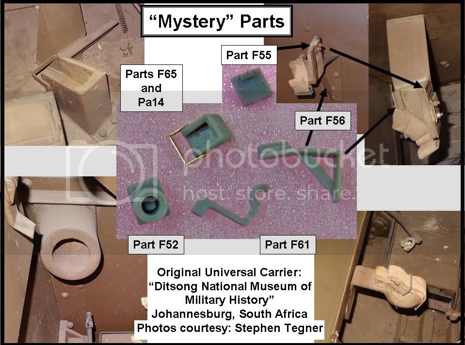
Here's a picture of the parts, keyed with the part numbers, and referenced to photos of the prototype:
We have parts F65 and Pa14 which create the butt stock rest in the gunner's front compartment. Parts F55 and F56 which form a rack or bracket located on the left fighting compartment's rear wall. Part F61 which forms a bracket on the left outer wall of the left rear fighting compartment, and part F52 which is, I think, a warm air outlet duct for the battery tray. (Because of scale dimension compromises, the kit does not include the warm air conduit from the radiator area to this duct.)
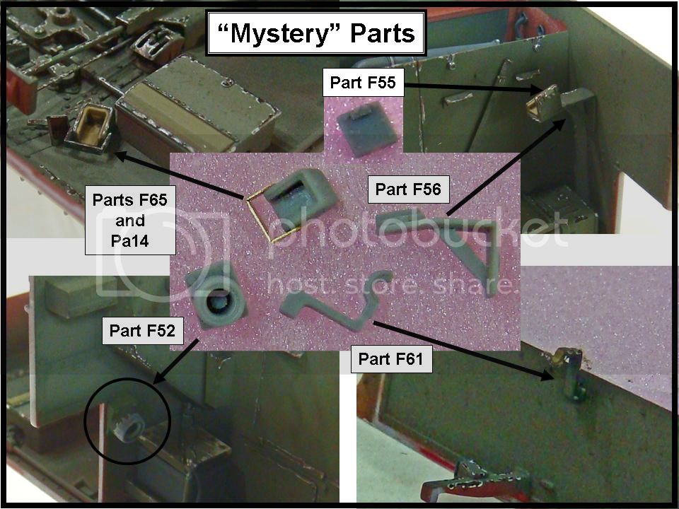
After painting and installing on the model, here are the same parts:
Note that all of these are pretty straight forward in their placement once you know what's going on.
Parts F65 and Pa14 fit into a locator hole in the gunner's compartment floor. Parts F55 and F56 fit into a locator hole on the rear hull wall. Part F61 fits between two "flanges" molded onto the lower left side hull (part A18) and curves up past the long stowage box mounted on the fender (step 24H).
The exception is part F52, the warm air duct (?). In step 16 on part E2, Riich would have your file or shave off the locating bump (looks like a small letter "U") for this part. This is correct, since the part cannot use the molded on bump. It places the part too far inboard. Shave off the bump and the two rivets outboard of it, and then mount the part even with the edge of the firewall part E2. Once the duct is moved slightly outboard, it will clear the battery tray per the prototype photo.
Note in the prototype photos that the pads or cushions on parts F55+F56, F61, and inside F65 are a tannish thick felt material. This is the same material in the bottoms of the rifle butt stock rests, parts E9 (step 20) and E21 (step 23).
These parts would have been much easier to install before I painted the interior, but they weren't too hard to place after the fact.
More to follow...
SdAufKla
South Carolina, United States
Joined: May 07, 2010
KitMaker: 2,238 posts
Armorama: 2,158 posts
Joined: May 07, 2010
KitMaker: 2,238 posts
Armorama: 2,158 posts
Posted: Tuesday, September 03, 2013 - 03:03 PM UTC
So, while Riich's "mystery" parts were keeping me up at night, I also did some more finishing work on the radio components.
I scratched up a Control Unit No. 2 (refer back to the earlier pencil sketches):
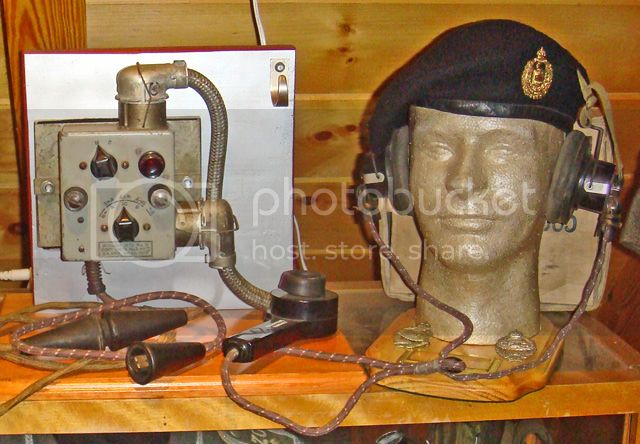
Here's the example in my personal collection that I used for reference:
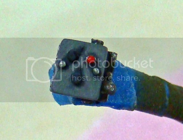
I also added a little detail to the variometer - a mounting bracket from a scrap of PE brass and the attachment point for the Aerial A coax cable on the bottom (styrene disks) and painted it up:
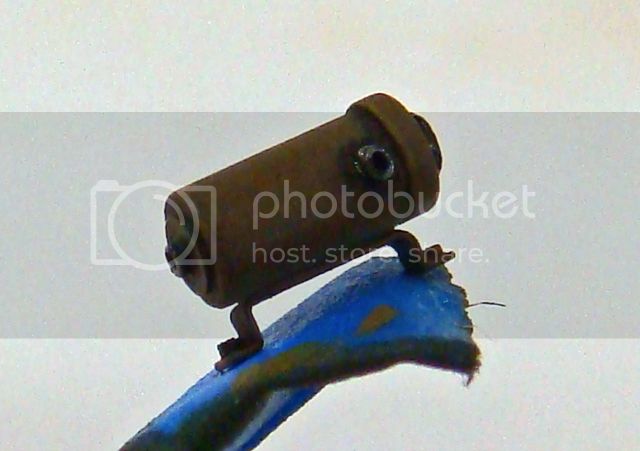
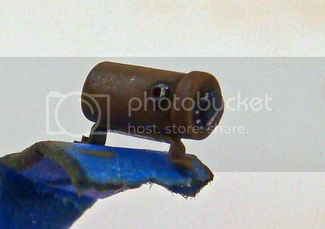
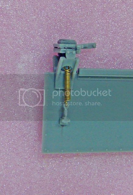
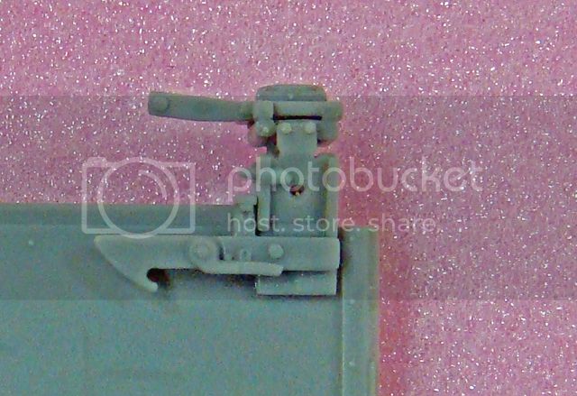
I also detailed the aerial base mounts. The kit has a very nice folding mount for the early No. 11 radio, and my No. 19 installation instructions show this is used for the Aerial A base. I added a new spring from brass wire and new chain links from some 40-links per inch chain:
I did have to fabricate a new Aerial B mount. I also made this from scrap PE brass and punched styrene bolt heads. It's a simple affair based on the drawing in the reference that I have - an inverted "L" with a triangular plate on the forward side and a couple of holes for the coax cable.
I'll fabricate the Aerial Base A and B later.
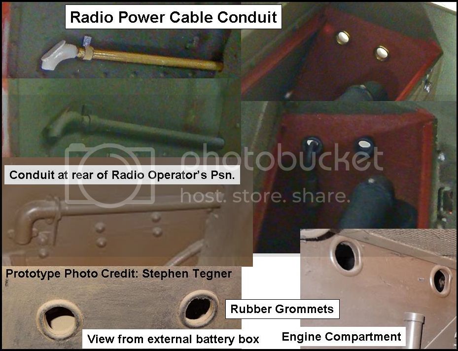
The major addition for the radio was the power cable conduit that is located on the rear hull wall. This conduit runs into the engine compartment, curves up, and the power cable then passes through a hole in the rear hull. The cable is protected by a rubber grommet in this hole, and attaches to the radio batteries that are stowed in the armored box on the rear hull (kit step 42Q).
Adding this was a big PITA! Had I known when I was building the engine and its compartment, it would have been easy-peasy. But trying to retro-fit the new parts to the already finished engine compartment and (mostly) finished radio operator's position really made me want to take some short-cuts. In the end, though, I figured out a sequence of steps that mitigated damaging the finished portions.
The conduit is made from a short section of Albion brass tubing. The mounting clamps are lead foil strips. The elbow at the radio operator's station is a piece of styrene rod bent at a 90 degree angle and attached to the brass tube. The grommets around the holes in the rear hull are rings of brass wire formed around the same drill bit used to make the holes. To glue them concentric to the holes, I used the butt end of the drill bit stuck back through the holes, slipped the rings over this, pulled the drill bit almost all the way out while still holding the rings in place. I then used a drop of extra thin CA applied to the ring. Before the glue set, I withdrew the drill bit leaving the rings attached to the inside of the holes.
The hardest thing about the whole process was having to handle the finished components and avoiding damage to the completed work.
More to follow...
SdAufKla
South Carolina, United States
Joined: May 07, 2010
KitMaker: 2,238 posts
Armorama: 2,158 posts
Joined: May 07, 2010
KitMaker: 2,238 posts
Armorama: 2,158 posts
Posted: Tuesday, September 03, 2013 - 03:20 PM UTC
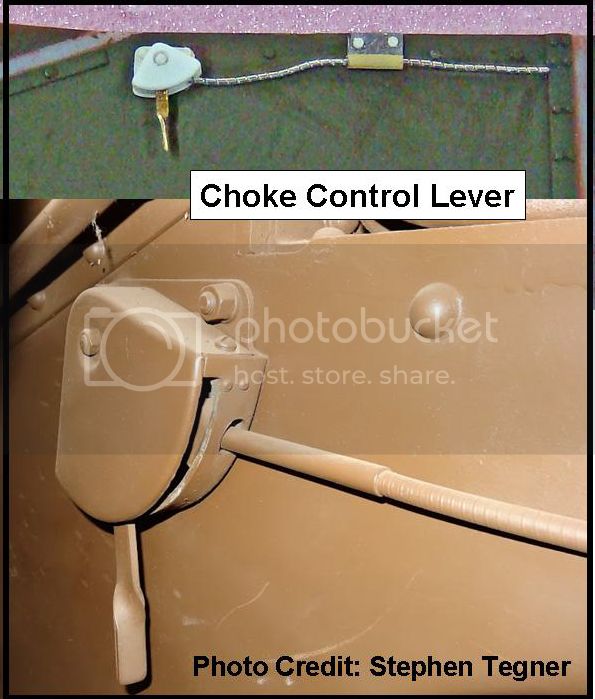
Well, the research corollaries to Murphy's Laws were really beating me up after I got Steve's photos. Not only did his photos show all the details of the radio power cable conduit, but it also showed the missing choke control lever and cable.
Riich molds the cable onto the surface of part A15 (step 6) next to the driver's station, but this detail is very shallow. Until I saw the prototype photos, I thought the detail was just some UI wire. However, with the prototype photos in hand, it was obvious that there's a pretty substantial fixture and device missing. What to do?
Oh you know...
Again, this wasn't too hard to fabricate - layered sheet styrene and a scrap of twisted leftover PE brass. As with the radio power cable conduit, working around already painted and partially finished sub-assemblies was the risky bit. Before I could add the new parts, I had to scrape off the original molded-on detail.
So, Steve's photos also showed a couple of easy improvements in the painting and finishing.
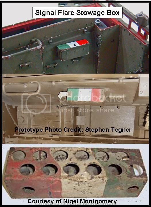
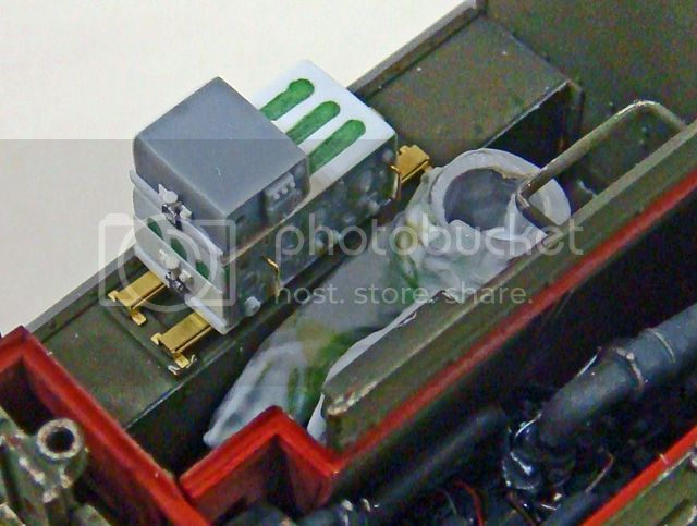
Next to the radio operator is a stowage box for signal flares. The top of this box is painted green, white and red, to indicate which color flare are located in which part of the box. Sounds a little overboard, but apparently, this was a standard practice on Commonwealth AFV's. The photo below shows the re-painted box on my model, the box on the Ditsong carrier, and another flare box removed from a British tank (I don't recall which).
The color adds a lot of interest, I think, and I'm glad I found out about it.
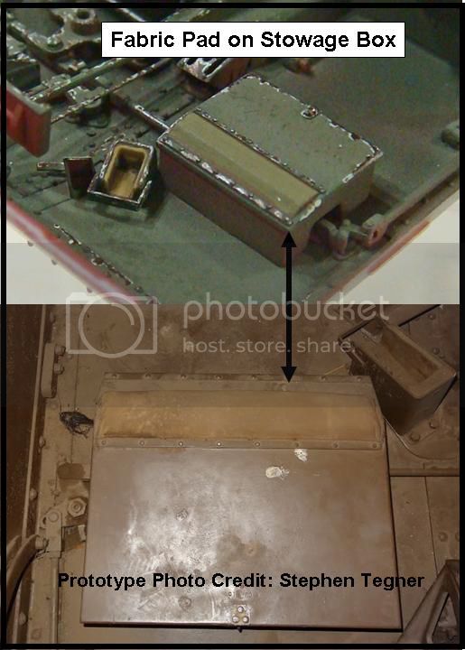
Another feature that I needed to repaint was the box located in the foot area of the gunner's station. I had assumed that the box was all metal, and had distressed and weathered mine accordingly. However, the Ditsong carrier photos clearly show that the box has a fabric pad on the top front edge. So, I repainted this detail:
So, almost done for this up-date, but one more post, I think...
SdAufKla
South Carolina, United States
Joined: May 07, 2010
KitMaker: 2,238 posts
Armorama: 2,158 posts
Joined: May 07, 2010
KitMaker: 2,238 posts
Armorama: 2,158 posts
Posted: Tuesday, September 03, 2013 - 03:36 PM UTC
All..righty, then, where am I now?
I confess, I'm a bit confused myself!
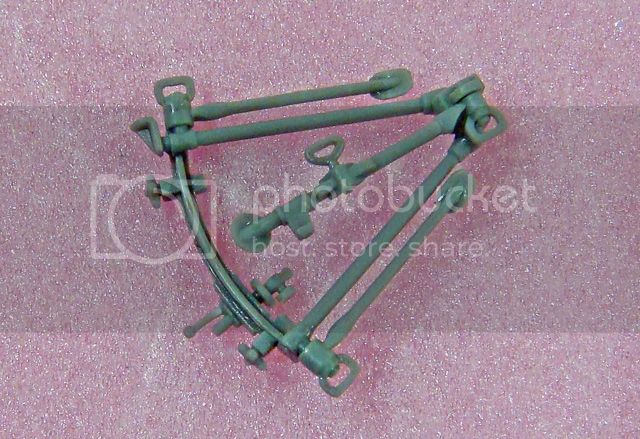
One of the most interesting parts in the Riich kit is the tripod for the Bren MG. It's an amazing bit of molding - a single part!
I just wanted to show it off before I painted it. As shown above, all I've done is clean up the mold / parting lines and used the tip of an X-acto knife to drill a small hole in the front pintle. What you see here is a single part. Pretty neat!
Here's the "bucket" for the tripod and the left rear rifle butt stock rests mounted on the wooden duck board (see previous posts). I took a picture just because...
Actually, this blurry shot shows all of the "mystery" parts installed in the rear fighting compartment along with the lower left hull and the above tripod "bucket" dry-fitted to see if all of this stuff would, in fact, fit into the carrier.
It does! (Will wonders never cease?!)
Since all that worked out so well, I'll be adding the Bren tripod and the anti-aircraft mount when I finish the carrier.
Here's the test fit:
I have no idea, really, if the anti-aircraft MG mount is supposed to go into the "mystery" brackets (F55, F56 and F61), but it seems to fit lengthwise, so, unless I find some information to the contrary, this is my plan.
The Bren tripod needs a couple of clamps to hold it to the engine compartment wall, and I'll make those by and by.
So, whew! Note to self: Up-date this blog more often!
Happy modeling!
jrutman
Pennsylvania, United States
Joined: April 10, 2011
KitMaker: 7,941 posts
Armorama: 7,934 posts
Joined: April 10, 2011
KitMaker: 7,941 posts
Armorama: 7,934 posts
Posted: Wednesday, September 04, 2013 - 01:55 AM UTC
I think this kit gets the over all prize for the most detail in the smallest area. Holy cow man.
Between the complexity of the kit itself(reference the tripod for the bren) and your skill in improving what is already a superb kit I am gobsmacked brother.
J
Between the complexity of the kit itself(reference the tripod for the bren) and your skill in improving what is already a superb kit I am gobsmacked brother.
J
Keef1648
South Carolina, United States
Joined: January 23, 2008
KitMaker: 1,240 posts
Armorama: 1,192 posts
Joined: January 23, 2008
KitMaker: 1,240 posts
Armorama: 1,192 posts
Posted: Wednesday, September 04, 2013 - 03:05 AM UTC
I agree Mike, I may be in Vegas but I still need my daily dose of Bren Carrier :-)
Great work Sir and coming along nicely.
Keith
Great work Sir and coming along nicely.
Keith
SdAufKla
South Carolina, United States
Joined: May 07, 2010
KitMaker: 2,238 posts
Armorama: 2,158 posts
Joined: May 07, 2010
KitMaker: 2,238 posts
Armorama: 2,158 posts
Posted: Thursday, September 05, 2013 - 11:00 AM UTC
@ Jerry: Yea, this entire kit reminds me of some sort of 1/35 scale aircraft cockpit build - all interior. Still, lots of fun and I'm learning a lot of obscure things about the Universal Carrier, for sure!
@ Keith: A daily dose of "Bren carrier" between your champagne bubble baths and shrimp quiche!
So, the Bren tripod is a pretty impressive bit of injection molding, and before I can close up the interior, I need to finish it up.
I spent a couple of happy hours at the painting bench and got the acrylics on it. While waiting for those to dry (and finally moving on to the long deferred interior weathering), I fell down the research "rabbit hole" once again!
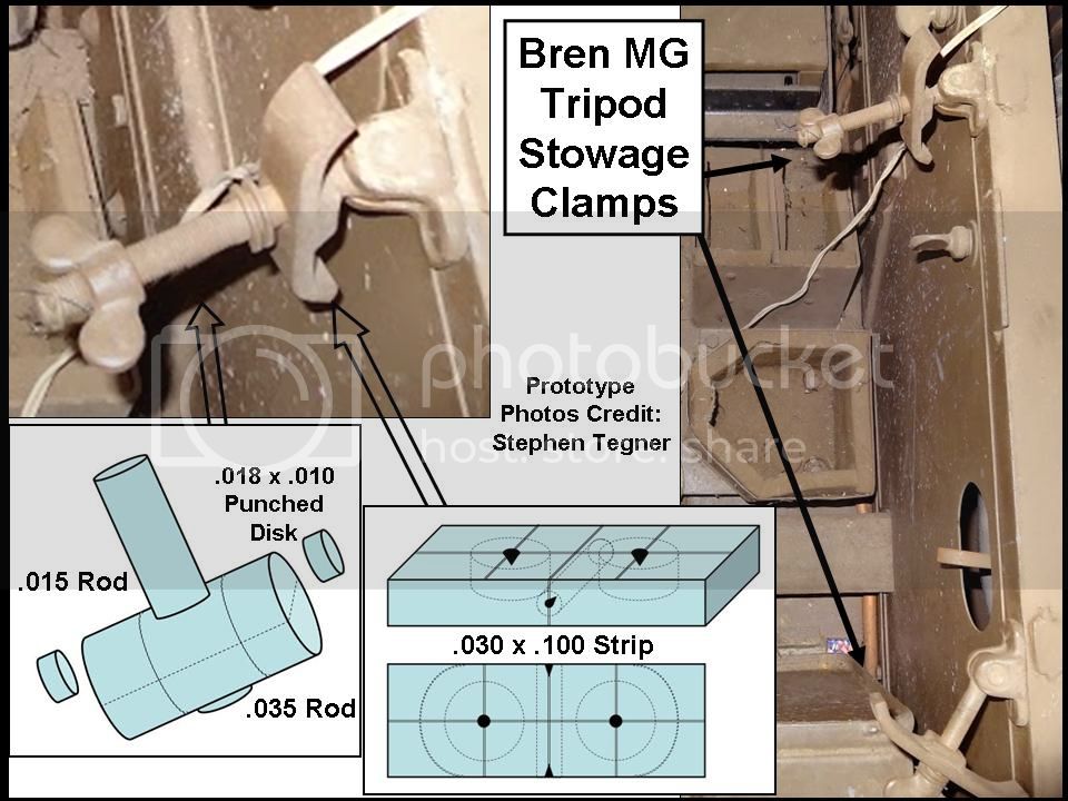
Steve Tagener's photos show the design and location of the stowage clamps that hold the tripod in place against the left side wall of the engine compartment. These are fairly simple fixtures and easily fabricated, so I thought I'd take a little tangent and show their construction in detail.
Hopefully no one will find this explanation too patronizing. If you're an experienced builder, and all this is "old hat" to you, I apologize in advance for boring you.
I get asked pretty often, though, by other model builders how to go about scratch-building this or that detail. To be honest, scratching up small details is actually pretty easy and straight forward. The key (at least for me) is to think the thing through and break the design of the desired new parts down into a collection of simple geometric shapes. Even very complicated fixtures are usually nothing more than cylinders, disks, and boxes grouped together. Building these is made much easier by taking each shape, in turn, as if it's a "sub-assembly" of the whole.
For instance, the choke control quadrant in the driver's station was a styrene circle or disk, cut into four equal pieces. Two of these were stacked and glued together. The third had a section of the curved edge cut away and then glued to the first two. The fourth section had a hole drilled into it for the recessed bolt and was then glued to the other three. This glued up "quadrant" was allowed to dry, and then it was sanded to its final shape and glued to a square of styrene with rounded and shaped corners. The choke handle, a rectangle of PE fret brass, was sanded round on one end, twisted 90 degrees using tweezers, and then glued into the slot formed by the section of the third piece of the styrene circle. The entire fixture is very "fiddly" and complicated looking when finished, but the actual work of scratch-building it was basically stacking quarter circles of styrene on top of each other.
In the next couple of posts, I'll demonstrate how I made the Bren MG tripod stowage clamps using the same process - Breaking the over all design into simple geometric shapes, fabricating those shapes, and then assembling them into my representation of the stowage clamps.
More to follow...
SdAufKla
South Carolina, United States
Joined: May 07, 2010
KitMaker: 2,238 posts
Armorama: 2,158 posts
Joined: May 07, 2010
KitMaker: 2,238 posts
Armorama: 2,158 posts
Posted: Thursday, September 05, 2013 - 11:26 AM UTC
First, we should consider the tools necessary for this work.
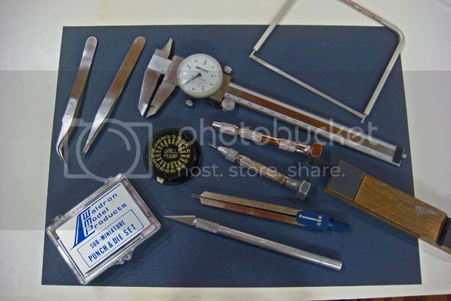
Here's a picture of all of the ones that I used while making these clamps (OK, I forgot the 2 oz hammer used for the punch and die set - But I actually punched out a couple hundred of the rivets used here and just keep them in a little beading jar, so I didn't actually use the punch and die set when making these clamps):
If you've been building models for any length of time, you probably have almost all of these on your own work bench.
A couple of notes, though.
The dial calipers are Mitoyo brand and are calibrated in millimeters and are accurate to .005 millimeters. These are one of the most used tools on my bench. I use them for scribing layout lines and measuring. Using them to scribe doesn't harm them on brass and plastic, and I've had this pair for over 25 years, and the tips are still nice and sharp. They're also relatively inexpensive, costing less than most new kits.
I use metric measurements on all of my work. The math is easy. However, if your brain works in fractional inches, by all means, carry on...
The Flexifile is a very handy tool, and the sanding strips can be cut very thin to get into small spaces (un-hook one end and pass it through the parts for interior sanding).
A decent sanding block also makes for much more precision in your basic construction work. I use wet-or-dry sandpaper and cut my own strips from larger sheets when ever I need them.
Fine tweezers are a must for handling small parts and with two pairs of tweezers, you can, with some practice, use both hands to manipulate parts. The ones shown, a #00 (straight tip) and a #07 (bent tips) have very little "spring" and are very easy to keep closed - very little finger pressure is needed, which in turn, helps with the fine-motor muscle coordination.
A pin-vise (hand drill) and drill bits are also essential for basic work as well as scratch-building. I've had this set for many, many years, and simply replace the drill bits that I break, as I break them (it happens).
I also have a second pin-vise with a compass needle that I use as a center-punch. I always center-punch a starter hole for any drilling. For close-in, detailed and precision work, you want the hole exactly where it's supposed to be. Slightly off is often the difference between a good part and a ruined part.
About the only "specialized" tool shown here is the set of "micro" punches. These are the best (but not the only) way to make small rivets and styrene disks. I use these to make replacement buttons on figures and all sorts to things. With care, they'll last and last. The Bren tripod stowage clamps could be made without the four .018 x .010 disks used to detail the bracket rods. "Salami" slices of stretched sprue or styrene rods could have been used.
These Waldron Sub-Miniature Punches and Dies costs about the same as some large kits. Expensive? I don't know... I use them all the time and have had them for many years. Prorated costs per build over all that time is probably just pennies per model.
So, this is it. Nothing mysterious or secret. Just basic hand tools that any modeler can acquire without breaking the bank.
More to follow...
SdAufKla
South Carolina, United States
Joined: May 07, 2010
KitMaker: 2,238 posts
Armorama: 2,158 posts
Joined: May 07, 2010
KitMaker: 2,238 posts
Armorama: 2,158 posts
Posted: Thursday, September 05, 2013 - 11:45 AM UTC
Now, on to the meat of the subject...
I studied the photos of the prototype parts and broke the design of the scratch-built parts into two basic fabrications. One is a pair of styrene rods, .015 and .035 in diameter. The other is a styrene strip .030 x .100.
(An exception to my metric always rule is the size of styrene stock. Evergreen sells their products sized in inch fractions, so that's what I use. If I need to convert these into metric, I simply grab my calipers and measure.)
Here's the prototype photos and sketches of the way I'll layout and make the styrene parts:
Note that the prototype threaded bracket bar is really a long eye-bolt held to the carrier by a base that's a pair of "ears" with a hing pin through them. All fine and dandy, but more detail than necessary for the model. What we will have is a half-cylinder (replicating the "ears") with a rod sticking out of it with two styrene disks on either end of the half cylinder (to replicate the hing pin). The flat part of the half cylinder will be the glue surface to the model.
As mentioned above, these bracket rods will be made from two pieces of styrene rod with punched styrene disks. The smaller rod will be glued into a hole drilled in the larger rod. This glue-up needs to dry overnight if you use plastic glue, but if you use CA (which I did), as soon as the CA sets, you can proceed.
The double-C clamps that hold the legs of the tripod will be made in an identical pair out of a piece of rectangular styrene stock. I'll drill holes in it, shape it, then cut it in to two double-C clamps. Making these as a pair ensures that the two double-C clamps on my model will be identical.
So, our complicated stowage clamp is really nothing more than simple cylinders and a rectangle with holes.
Don't believe me? Follow along...
PS: I will use commercially available wing nut castings. I'm not really crazy!
SdAufKla
South Carolina, United States
Joined: May 07, 2010
KitMaker: 2,238 posts
Armorama: 2,158 posts
Joined: May 07, 2010
KitMaker: 2,238 posts
Armorama: 2,158 posts
Posted: Thursday, September 05, 2013 - 12:17 PM UTC
The first thing I actually did was to drill the holes in the .035 dia. rod using a #77 drill bit (.018" or .045mm) for the .015 dia. rod sections. I set this aside for the CA glue to set while I worked on the actual double-C clamps. But more on the rod glue-up in the next post.
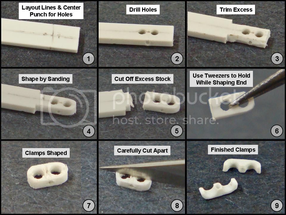
Here's the step-by-step on making the double-C clamps out of the rectangular strip:
I first laid out the locations for the holes. I measured the center lines of the tripod legs to establish the distance between the large holes. I then "measured" the diameter of the tripod legs by holding up drill bits next to them until I got the closest match. Since I'm limited to the sizes of the drill bits at hand, the closest match is as good as it gets.
Here I used a #65; .035"; .09mm drill bit for the large holes. The small cross hole is made with a #77; .018"; .045 mm drill bit (the size needed for the .015" styrene rod).
(Scratch-builders' secrets, like what goes on in Vegas, stay in the workroom - except here! "Close-enough is often as good as it gets." Remember that everything we model-builders do is representational.)
I used my calipers to scribe a line down the centers of both top and bottom (wide sides) of the styrene strip. I then reset the calipers to 2 mm and made witness marks on both the top and bottom from the tip of the strip. This intersection is the location of the first large hole. I then reset my calipers to the distance between the large hole centers and made a second mark, measured from the first on the center lines on both top and bottom. This is the location of the second large hole. I then took one half of the distance between the large holes, added it to 2 mm and scribed lines on both sides, measured from the tip of the strip between the large hole locations. I carried these lines around the narrow sides of the strip. The centers of the sides on this line are the locations for the small hole to be drilled from narrow side to narrow side.
In the photograph, these layout lines are emphasized by tracing over them with a pencil.
The smaller the parts, the more need for precision, and that's why I laid out the centers of the holes on all four sides of the strip. In the next step, I will drill out each hole halfway through from each opposite side. This ensures that the holes are located exactly where they should be.
In step three, I trimmed away as much of the excess stock as I could with an X-acto knife. As with the holes, I did this trimming from both sides, alternating side to side to keep the cuts as even as possible.
Remember, when cutting with an X-acto knife, the edge of the blade is beveled, so the angle that the knife is held in respect to the working surface of the part must account for this. That is, you often have to angle the top edge of the blade AWAY FROM the "good" side of the cut to make that side square and allow the waste to take up the angle from the knife bevel.
In step four, I shaped and smoothed the new part using my sanding block while holding the excess stock end of the styrene strip. This is a good "rule of thumb" when fabricating very small parts - keep them on the excess stock as long as possible so that the final work area is as small as possible.
By step 5, I've done all the shaping of the part that's possible while still attached to the excess stock, so the excess is now cut off.
In step 6, I use a pair of tweezers to now hold the part while I finish shaping it with the sanding block - here just basically rounding off the cut-off end. The rest is already good, so as little as possible is done while holding with the tweezers.
Step 7 shows the final exterior shape of the two double-C clamps still attached to each other.
In step 8, I carefully cut the two clamps apart using the still visible center layout lines. I did this, again, by cutting part the way through from each side, alternating side to side, until the two parts separated. Alternating like this minimizes the effect of the knife edge bevel and gives a straight cut to both sides.
Step 9 shows the two double-C clamps after some light clean-up with the Flexifile - ready to use.
Told ya...
SdAufKla
South Carolina, United States
Joined: May 07, 2010
KitMaker: 2,238 posts
Armorama: 2,158 posts
Joined: May 07, 2010
KitMaker: 2,238 posts
Armorama: 2,158 posts
Posted: Thursday, September 05, 2013 - 12:47 PM UTC
By now the bracket rod glue-ups have set and are ready for fabrication.
After the double-C clamps, these are a piece of cake.
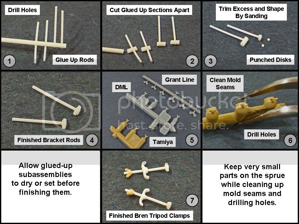
Again, here's the step-by-step on how these parts were made:
Step 1 shows the glue-up after it had set. (The extra through pieces are for another project.)
In step 2 we section the glued-up rod pieces.
Note: An alternative would be to shape each glued-up section in succession, one-after-the-other, so that the excess stock can be used as a convenient handle. You could also start with half-round styrene rod stock - I would have done this if I had had any.
Step 3 shows one section with half of the thick rod sanded into a semi-cylinder (is "semi-cylinder" a word?) with its ends shortened to the final width. Next to it are the two .018 x .010 punched styrene disks. For the shaping, I used tweezers to hold the part and the sanding block and Flexifile to shape it.
Step 4 shows the two finished bracket rods. Very simple.
In step 5 we can see three options for the commercial wing nut castings - Grant Line, DML (left over from one of their Panzer IV series kits - you get lots of these!), and Tamiya (left over from one of their re-released Italian M13/40 kits). I chose the Tamiya parts since they're not quite as detailed as the DML or Grant Line, but this won't be visible since these are going to buried deep in the bowels of the carrier.
In keeping with the rule of thumb to work on small parts for as long as possible while they're still attached to the excess stock (or here, the sprue), in step 6 you can see that I used the Flexifile to clean-up the mold seam lines and then I drilled the holes into the wing nuts. I started with a #80 drill bit and chased the holes with larger bits until I reached the #77; .018" (.045 mm).
(Note that the .018" hole is the right size for the .015" plastic rod.)
Step 7 shows the finished Bren MG tripod stowage clamps. They look very complicated and fiddly, but as you can see, they're really nothing but a couple of simple geometric shapes glued together.
So, the big question is: How do these look on the model?!
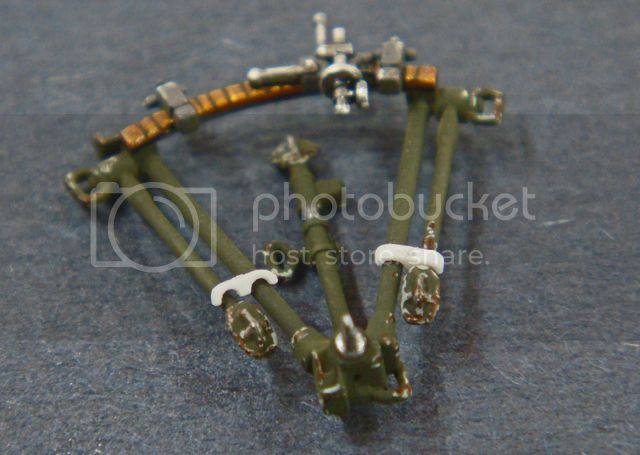
Here's a picture of the double-C clamps test fitted to the tripod:
I turned one on its side for the photo so that you could see the form better. If you didn't know, you'd have a hard time believing that it started out as a piece of rectangular styrene stock.
Here're the completed clamps, again, test fitted to the tripod:
Note that I've left the double-C clamps and wing nuts loose so that I can adjust the final length on the model for a good fit to the engine compartment wall.
And, finally, here's a look at the tripod and clamps test fitted in the carrier:
By the way, Riich would have you fit the tripod in the carrier with the other side facing outward. I tried it that way, but the tripod just doesn't fit "right." Going by the old engineer's saying that "If it looks right, it probably is," once I turned the tripod around, it fit like it belonged.
How long did it take to make the stowage clamps? Including the photography, about an hour and a half. (By comparison, it's taken me about four times a long to edit the photos, create the graphics, and write up these posts!)
So, there you have it! I hope I haven't insulted anyone's intelligence with the extensive explanation, but scratch-building small details like this is a joy, and one that no modeler should be intimidated by.
And when you get something as nice as Riich's little carrier (and that tripod!), adding a few touches all your own is just about irrepressible!
Happy modeling!