Hordaland, Norway
Joined: July 09, 2009
KitMaker: 197 posts
Armorama: 194 posts
Posted: Thursday, February 25, 2010 - 10:16 PM UTC
http://plasticmodeling.blogspot.com/
Gauteng, South Africa
Joined: October 27, 2009
KitMaker: 69 posts
Armorama: 44 posts
Posted: Thursday, February 25, 2010 - 10:54 PM UTC
Glad I could help...

Looking good so far

How are you going to join the floors to the walls?

Scotland, United Kingdom
Joined: April 30, 2007
KitMaker: 1,597 posts
Armorama: 806 posts
Posted: Friday, February 26, 2010 - 01:00 AM UTC
Jarle
Looking good so far and I like the way you are shuttering the formwork to build the pour up. Apart from using loge (tee hee) this is how the real thing could be constructed in pours of between 1m and 3m height, depending on the complexity and strength of the formwork providing support to each pour.
A consiquence of this is that you could end up with very distinct horizontal and vertical construction joints at the point where each pour starts and stops. This may be something you want to have on your finished walls too to have the real pour sequence showing through in your model. Maybe add a very thin strip of balsa on the face of the next pour which you can pull out after it has set.
I don't know if you will need this, but it is something to think about, if your own plaster sequence sets at different times, you may end up with the plaster being weak at each join to the next pour and might simply crack if lifted off because the section below is already set hard and your wall thickness is so thin. If you drill in some holes and set some paper clips in the centre of the thickness this will act as reinforcement bars. Aside from giving the junction a bit of possible strength you can then say you have real reinforced concrete modelled. Depending how you want your model to look at the edges you could have the paperclips sticking though you would have to look at real reinforcement to make this effect look convincing.
Nige
"Procrastination is the art of keeping up with yesterday."
Don Marquis
Procrastination isn't the problem, it's the solution. So procrastinate now, don't put it off.
Ellen DeGeneres
Hordaland, Norway
Joined: July 09, 2009
KitMaker: 197 posts
Armorama: 194 posts
Posted: Friday, February 26, 2010 - 03:08 AM UTC
Quoted Text
Jarle
Looking good so far and I like the way you are shuttering the formwork to build the pour up. Apart from using loge (tee hee) this is how the real thing could be constructed in pours of between 1m and 3m height, depending on the complexity and strength of the formwork providing support to each pour.
A consiquence of this is that you could end up with very distinct horizontal and vertical construction joints at the point where each pour starts and stops. This may be something you want to have on your finished walls too to have the real pour sequence showing through in your model. Maybe add a very thin strip of balsa on the face of the next pour which you can pull out after it has set.
I don't know if you will need this, but it is something to think about, if your own plaster sequence sets at different times, you may end up with the plaster being weak at each join to the next pour and might simply crack if lifted off because the section below is already set hard and your wall thickness is so thin. If you drill in some holes and set some paper clips in the centre of the thickness this will act as reinforcement bars. Aside from giving the junction a bit of possible strength you can then say you have real reinforced concrete modelled. Depending how you want your model to look at the edges you could have the paperclips sticking though you would have to look at real reinforcement to make this effect look convincing.
Nige
Nice idea about the reinforcement. Maybe i should drill some thin holes and use copper wires as a similar iron reinforcement to the real thing. We watched a film at my old job that the reason that the bunkers could take so much beating is that they used 3 or 4 times more iron reinforcement as they do today in standard buildings. Hmm. Maybe an idea for another diorama, to show an damaged bunker with the reinforcement showing..
I think i will make it in sections and ensure that they fit together an glue them. Then use some kind of compound to hide the overlapping. But i liked the idea about the concrete stage overlapping line. Maybe ill just build the mold even taller. and continue the job like they do it in real life. It was kinda fun doing it this way. Like doing it for real. Just in a smaller scale hehe.
Ohh well, time to dismantle the mold and see how it came out. Will post pictures
http://plasticmodeling.blogspot.com/
Hordaland, Norway
Joined: July 09, 2009
KitMaker: 197 posts
Armorama: 194 posts
Posted: Friday, February 26, 2010 - 03:37 AM UTC
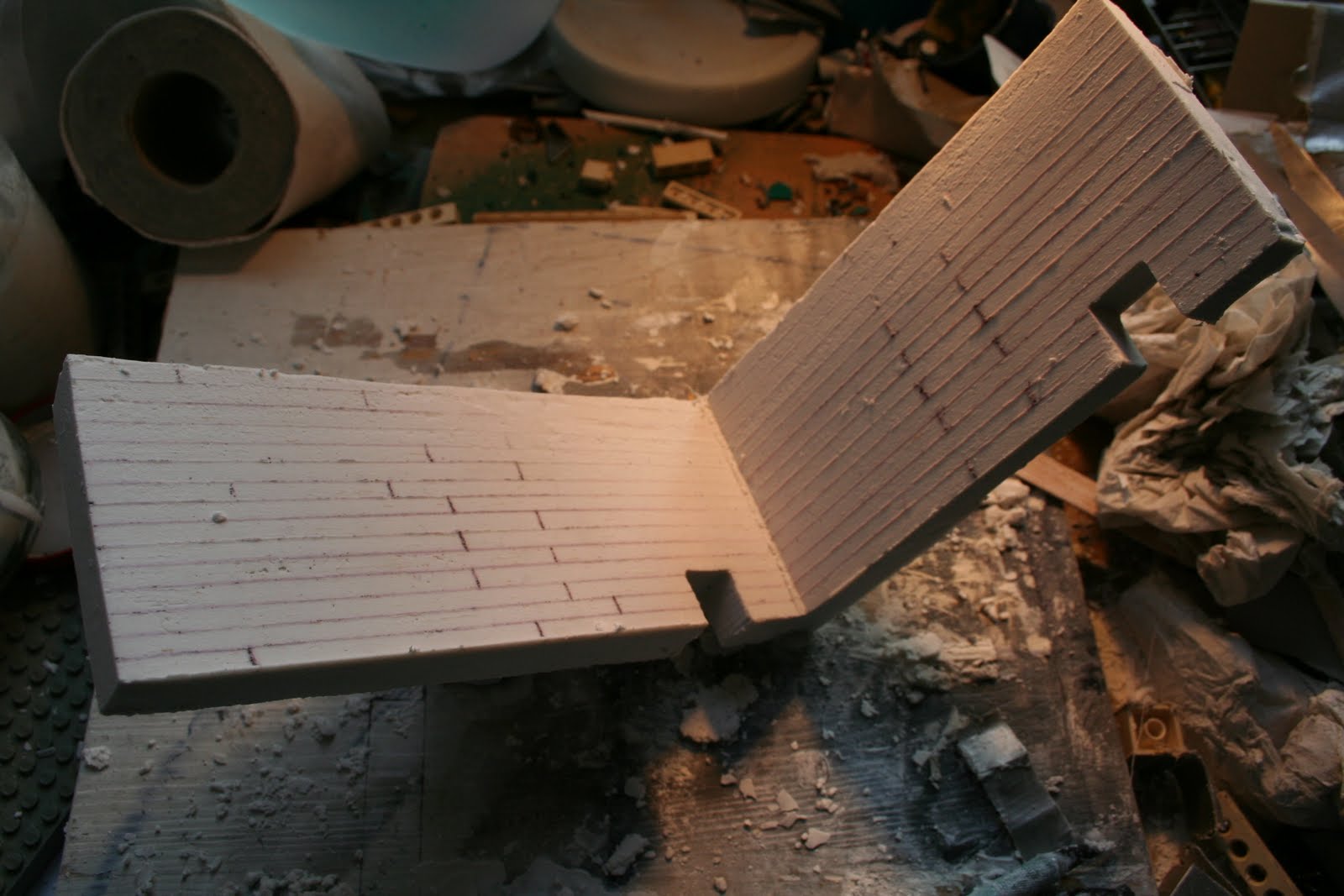
First wall finished. Will cut away all unevenness on the wall before continuing.
http://plasticmodeling.blogspot.com/
Indiana, United States
Joined: August 19, 2007
KitMaker: 2,184 posts
Armorama: 1,468 posts
Posted: Friday, February 26, 2010 - 06:07 AM UTC
Jarle, looking very real for poured concrete. I like the seepage between the boards. Here I'll pipe in some more info for you ( couldn't resist that) For your piping take a look at the model rail road section at your LHS for cornerstone products. They have an oil pumping set of pipes that I have used for my dio's. A lot of useful things including hand wheel shut off vavles and wall mount supports. Various thickness's of piping and angles. Used them for water piping in a building for the N.Y.P.D. emergincy services set by D.M.L. and came out pretty convincing. I think they scale out to about a 4" pipe or close enough depending on which ones you use. Hope it helps soom. bob d.
There is no return policy on time spent
Hordaland, Norway
Joined: July 09, 2009
KitMaker: 197 posts
Armorama: 194 posts
Posted: Friday, February 26, 2010 - 07:18 AM UTC
Quoted Text
Jarle, looking very real for poured concrete. I like the seepage between the boards. Here I'll pipe in some more info for you ( couldn't resist that) For your piping take a look at the model rail road section at your LHS for cornerstone products. They have an oil pumping set of pipes that I have used for my dio's. A lot of useful things including hand wheel shut off vavles and wall mount supports. Various thickness's of piping and angles. Used them for water piping in a building for the N.Y.P.D. emergincy services set by D.M.L. and came out pretty convincing. I think they scale out to about a 4" pipe or close enough depending on which ones you use. Hope it helps soom. bob d.
Tnx for the tip. Much appreciated. Pipes and such are not exactly easy to come by. Thought about getting myself a small tube bending tool and buy some pipes used for billing boats ships and such.
I kinda wish i didnt take the mold apart. And just continued the work. But had to check if the proses worked again. And that there where no bubbles. So now i have to re build the whole thing :/ hehe. Ahhr, next time.
http://plasticmodeling.blogspot.com/
Sachsen, Germany
Joined: November 28, 2007
KitMaker: 1,462 posts
Armorama: 1,289 posts
Posted: Friday, February 26, 2010 - 07:32 AM UTC
The structure of the "beton" (correct name?) looks good!
I also have seen this type of walls somewhere.
I wait for the lot of tiles on the wall.

Good luck for this.
Will you attach the rubber-mats? (on the tiles)
greetings...
Soeren
progress:
- Venera-14-lander on Venus
- Dragon s.10cm K18 at the Atlantic-wall
completed:
- Venera-10 lander on Venus
Hordaland, Norway
Joined: July 09, 2009
KitMaker: 197 posts
Armorama: 194 posts
Posted: Friday, February 26, 2010 - 07:39 AM UTC
Quoted Text
The structure of the "beton" (correct name?) looks good!
I also have seen this type of walls somewhere.
I wait for the lot of tiles on the wall. Good luck for this.
Will you attach the rubber-mats? (on the tiles)
greetings...
Soeren
Allmost, Its betong
I studdied some bunker complexes not far from here and i noticed this plank mold technique clearly being used there. Will show photos
Im a little confuzed, rubber matts?
http://plasticmodeling.blogspot.com/
Hordaland, Norway
Joined: July 09, 2009
KitMaker: 197 posts
Armorama: 194 posts
Posted: Friday, February 26, 2010 - 08:21 AM UTC
http://plasticmodeling.blogspot.com/
Hordaland, Norway
Joined: July 09, 2009
KitMaker: 197 posts
Armorama: 194 posts
Posted: Friday, February 26, 2010 - 08:37 AM UTC
http://plasticmodeling.blogspot.com/
Noord-Brabant, Netherlands
Joined: January 13, 2006
KitMaker: 65 posts
Armorama: 22 posts
Posted: Friday, February 26, 2010 - 10:35 PM UTC
Intresting Pictures, The tank tho looks more like a British cromwell to me.
Sachsen, Germany
Joined: November 28, 2007
KitMaker: 1,462 posts
Armorama: 1,289 posts
Posted: Friday, February 26, 2010 - 11:14 PM UTC
Beautiful landscape where you live!
Quoted Text
The housing of this device in an underground chamber lined with ceramic brick and rubber mats suggests that it gave off extremely strong electro-magnetic or electro-static field effects as well as high heat when in operation.
from:
http://discaircraft.greyfalcon.us/DIE%20GLOCKE.htm Perhaps this helps a bit.
greetings...
Soeren
edit:
On the lower part of the page can be found:
"The test chamber was 30 meters square and lined with ceramic tiles. The floors and walls were covered with heavy black rubber mats."
progress:
- Venera-14-lander on Venus
- Dragon s.10cm K18 at the Atlantic-wall
completed:
- Venera-10 lander on Venus
Hordaland, Norway
Joined: July 09, 2009
KitMaker: 197 posts
Armorama: 194 posts
Posted: Saturday, February 27, 2010 - 04:27 AM UTC
Quoted Text
Beautiful landscape where you live!
Quoted Text
The housing of this device in an underground chamber lined with ceramic brick and rubber mats suggests that it gave off extremely strong electro-magnetic or electro-static field effects as well as high heat when in operation.
from:
http://discaircraft.greyfalcon.us/DIE%20GLOCKE.htm
Perhaps this helps a bit.
greetings...
Soeren
edit:
On the lower part of the page can be found:
"The test chamber was 30 meters square and lined with ceramic tiles. The floors and walls were covered with heavy black rubber mats."
I remember this from the documentary. But then again i have to confine it to the 30x30 size. So this is very much a fictional dio. Or a improved internal radiation shielding in the bell itself.
But ill see what ill do about the mats or if i leave it pure concrete. Hmm.
http://plasticmodeling.blogspot.com/
Hordaland, Norway
Joined: July 09, 2009
KitMaker: 197 posts
Armorama: 194 posts
Posted: Saturday, February 27, 2010 - 05:49 AM UTC
This might be interesting to see. I found it very inspirational.
http://www.youtube.com/watch?v=sABpGFzxebQ&feature=relatedhttp://plasticmodeling.blogspot.com/
Sachsen, Germany
Joined: November 28, 2007
KitMaker: 1,462 posts
Armorama: 1,289 posts
Posted: Saturday, February 27, 2010 - 06:42 AM UTC
Thanks!
Today, I found a 5-part documentation on youtube. Very interesting stuff!
first part is:
http://www.youtube.com/watch?v=b8e6wUfueBo&feature=related Thanks to the publisher!
greetings...
Soeren
progress:
- Venera-14-lander on Venus
- Dragon s.10cm K18 at the Atlantic-wall
completed:
- Venera-10 lander on Venus
Busan, Korea / 대한민국
Joined: May 22, 2008
KitMaker: 40 posts
Armorama: 39 posts
Posted: Saturday, February 27, 2010 - 08:00 AM UTC
Hi,
I have been following this interesting post.
Btw, the tank seems a US sheridan . Why is it there?

Cheers!
Seung-il
Hordaland, Norway
Joined: July 09, 2009
KitMaker: 197 posts
Armorama: 194 posts
Posted: Saturday, February 27, 2010 - 11:13 AM UTC
Thats the one i watched on tv. I remember my mind exploding with ideas after the first time i saw it. Only irritating thing is that we will never know for sure if any of it is true.
http://plasticmodeling.blogspot.com/
Hordaland, Norway
Joined: July 09, 2009
KitMaker: 197 posts
Armorama: 194 posts
Posted: Saturday, February 27, 2010 - 11:38 AM UTC
Quoted Text
Hi,
I have been following this interesting post.
Btw, the tank seems a US sheridan . Why is it there?
Cheers!
Seung-il
Its way over a decade old, and its just stored there. Rotting away

http://plasticmodeling.blogspot.com/
Hordaland, Norway
Joined: July 09, 2009
KitMaker: 197 posts
Armorama: 194 posts
Posted: Wednesday, March 03, 2010 - 06:30 AM UTC
The molding continues.
Here is the mold reinforced with legoes. Decided to cut out and carve the windows after the wall is done.


http://plasticmodeling.blogspot.com/
Scotland, United Kingdom
Joined: April 30, 2007
KitMaker: 1,597 posts
Armorama: 806 posts
Posted: Wednesday, March 03, 2010 - 07:31 AM UTC
Jarle
I have to say I think the molded in windows will look a lot better than trying to carve them out after. You have done such a great job of mimiking the timber formwork that they used in real life, including where they were forming large and small opening in the concrete.
The real windows would have been formed by building a basic timber box and supporting it within the mold (and real reinforcement) and letting the concrete pour in around the formwork even where a window opening is in the mid height of the wall..
The window and door formwork would then be struck out unless they needed fixings for items like pass doors or window frames. Where formwork wasn't to be left the wood pattern of the struck formwork would likely show on the concrete at these large openings too.
Cutting holes in the real concrete to make a new opening is far harder than it might appear even with modern tools given the thickness and the strength of the materials.
As well as that making the formwork for your viewing windows there is more chance that you will get the shapes nearly identical but with a variation in the struck formwork. Formwork could even let you get a nice downward slope of the window cill to enable the viewer to look downwards into the test area that might be hard to carve out of your molded wall accurately.
Hope that doesn't sound nit picking but I thought your first version was great and casting it the way they would do it for real might give you the look you are looking for.
All the best
Nige
"Procrastination is the art of keeping up with yesterday."
Don Marquis
Procrastination isn't the problem, it's the solution. So procrastinate now, don't put it off.
Ellen DeGeneres
Hordaland, Norway
Joined: July 09, 2009
KitMaker: 197 posts
Armorama: 194 posts
Posted: Wednesday, March 03, 2010 - 07:39 AM UTC
Quoted Text
Jarle
I have to say I think the molded in windows will look a lot better than trying to carve them out after. You have done such a great job of mimiking the timber formwork that they used in real life, including where they were forming large and small opening in the concrete.
The real windows would have been formed by building a basic timber box and supporting it within the mold (and real reinforcement) and letting the concrete pour in around the formwork even where a window opening is in the mid height of the wall..
The window and door formwork would then be struck out unless they needed fixings for items like pass doors or window frames. Where formwork wasn't to be left the wood pattern of the struck formwork would likely show on the concrete at these large openings too.
Cutting holes in the real concrete to make a new opening is far harder than it might appear even with modern tools given the thickness and the strength of the materials.
As well as that making the formwork for your viewing windows there is more chance that you will get the shapes nearly identical but with a variation in the struck formwork. Formwork could even let you get a nice downward slope of the window cill to enable the viewer to look downwards into the test area that might be hard to carve out of your molded wall accurately.
Hope that doesn't sound nit picking but I thought your first version was great and casting it the way they would do it for real might give you the look you are looking for.
All the best
Nige
Hey. I know. I will do it next time i am doing anything similar. But i didnt have the necessary materials to make the window shapes. So ill carve them carefully out and if i f... it up. il use supersculpy or cernit to make it look the same as the other.
Hope this looks any good. I had to paint the lower finished part for the tape to stick to it. So the mold would not leak.

http://plasticmodeling.blogspot.com/
Sachsen, Germany
Joined: November 28, 2007
KitMaker: 1,462 posts
Armorama: 1,289 posts
Posted: Wednesday, March 03, 2010 - 07:39 AM UTC
Thanks for the images!
This gives some impression of the build and "how to make them".
greetings...
Soeren
edit:
Wow, the result looks very good!
progress:
- Venera-14-lander on Venus
- Dragon s.10cm K18 at the Atlantic-wall
completed:
- Venera-10 lander on Venus
Hordaland, Norway
Joined: July 09, 2009
KitMaker: 197 posts
Armorama: 194 posts
Posted: Wednesday, March 03, 2010 - 07:49 AM UTC
Quoted Text
Thanks for the images!
This gives some impression of the build and "how to make them".
greetings...
Soeren
edit:
Wow, the result looks very good!
My pleasure
Always happy to share my stuff. The hobby was not the same before i found armorama.
I might actually carve out the enire size of the window and make a window mold so the sides are angled like i drew on the autocad drawings (maybe hard to see). It became to difficult to make the angled window edges on the mold frame cuz of flexes and such. So i might skip the carving and just cut out the window frame and remold a new angled window frame. How does that sound Nige?
http://plasticmodeling.blogspot.com/
Scotland, United Kingdom
Joined: April 30, 2007
KitMaker: 1,597 posts
Armorama: 806 posts
Posted: Wednesday, March 03, 2010 - 11:06 AM UTC
Hi there mate
Tee hee ,,,,,,,,,,, your work is looking great as it is !!!!!!!!!!!!!!!!! That formwork inprint just rocks. Looking forward to seeing how this progresses as I work in the building industry and it is great when you see someone like yourself build something that catches the look of the real thing so well.
I think the painted section looks great and gives a look of the sort of part painted walls you see in some places.
Hope whatever way you do this works out for ya. Either way I is following this build !!!!!!!

Nige
"Procrastination is the art of keeping up with yesterday."
Don Marquis
Procrastination isn't the problem, it's the solution. So procrastinate now, don't put it off.
Ellen DeGeneres