After a hard time finding my model-building mojo following my last marathon project, I've finally decided on doing a "simple" out of the box build, the Riich Models RV35011 "Universal Carrier, Mk. I."
For those interested in what's in the box, I recommend this review by Darren Baker: Armorama::In-Box Review::Riich Models Universal Carrier
I won't repeat what Darren had to say or show about the kit. Needless to say, the kit has around 600 parts which come together into a finished build that will easily fit into the palm of your hand. I'm a hard guy to impress when it comes to model kits, but I have to say that Riich has impressed me.
For anyone contemplating starting this kit, I highly recommend Terry Ashley's full build review on PMMS: PMMS::Riich Models Universal Carrier::Full Build Review . Terry points out several mistakes in the kit instructions, but what's even more important, his review suggests that the building sequence in the instructions be radically modified to make the build much easier and more logical. I've taken Terry's advice to heart with my own build.
In the next post, I'll put up a few happy snaps of my progress so far...
Hosted by Darren Baker
Riich Models RV35011
SdAufKla

Joined: May 07, 2010
KitMaker: 2,238 posts
Armorama: 2,158 posts

Posted: Saturday, August 03, 2013 - 11:41 AM UTC
SdAufKla

Joined: May 07, 2010
KitMaker: 2,238 posts
Armorama: 2,158 posts

Posted: Saturday, August 03, 2013 - 11:58 AM UTC
To get started, I did go with the kit's recommended step number 1, the full engine build.
Riich gives the builder a very complete Ford Flat-head V-8 engine that I found a joy to build. In fact, it was so nice that I couldn't resist adding and few missing details and then planning my completed build around some way to display the engine. More on that idea later.
Here're a couple pics of the completed engine:
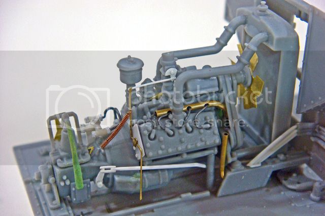
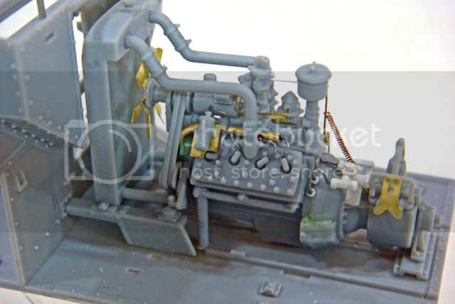
These two pics show the engine dry-fitted into its compartment. Note that the engine mounts, radiator, fan and generator, and forward firewall are all just press-fit on. It all comes apart for painting later.
Here's a pic of the engine removed with the radiator, fan and generator and motor mounts removed:
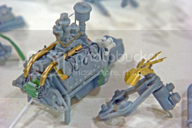
Just about everything in the photo that's not gray plastic has been added. (The fan and coil mount are kit PE.) The major missing parts are the "crab" distributor on the front, the conduits for the ignition wires and the clutch lever and linkage.
I've also added the fuel line from the fuel pump-filter to the carburetor and the throttle linkage to the carb.
I have extended the transmission shifter lever down about 4 mm and terminated it with the socket to receive the shifter linkage ball (scratch built but not shown yet).
Still to add after painting are some of the electrical wires (coil to ignition, generator to driver's compartment, and the water temp and oil pressure).
Riich gives the builder a very complete Ford Flat-head V-8 engine that I found a joy to build. In fact, it was so nice that I couldn't resist adding and few missing details and then planning my completed build around some way to display the engine. More on that idea later.
Here're a couple pics of the completed engine:


These two pics show the engine dry-fitted into its compartment. Note that the engine mounts, radiator, fan and generator, and forward firewall are all just press-fit on. It all comes apart for painting later.
Here's a pic of the engine removed with the radiator, fan and generator and motor mounts removed:

Just about everything in the photo that's not gray plastic has been added. (The fan and coil mount are kit PE.) The major missing parts are the "crab" distributor on the front, the conduits for the ignition wires and the clutch lever and linkage.
I've also added the fuel line from the fuel pump-filter to the carburetor and the throttle linkage to the carb.
I have extended the transmission shifter lever down about 4 mm and terminated it with the socket to receive the shifter linkage ball (scratch built but not shown yet).
Still to add after painting are some of the electrical wires (coil to ignition, generator to driver's compartment, and the water temp and oil pressure).
SdAufKla

Joined: May 07, 2010
KitMaker: 2,238 posts
Armorama: 2,158 posts

Posted: Saturday, August 03, 2013 - 12:15 PM UTC
Terry Ashley made a very good suggestion in his PMMS build review that the kit assembly sequence should be modified to allow the floor and interior to built more easily.
Riich would have you add the hull side walls and then build the steering and brake linkages, add the engine and compartment, and then complete the driver / gunner forward compartment. This is just possible, as Terry demonstrated in his review, but it really makes no sense. It also makes any interior painting very difficult, if not impossible.
Also, I intend to add all three crew figures. In order to fit the crew into the vehicle, they must be assembled at the same time as the carrier or it will be impossible to get them to fit later.
With this in mind, I've skipped all over the instructions to build sub-assemblies and finish the hull floor and much of the front crew compartment first.
After the engine, I added the floor hing-mounts for the front seats and then built the seats.
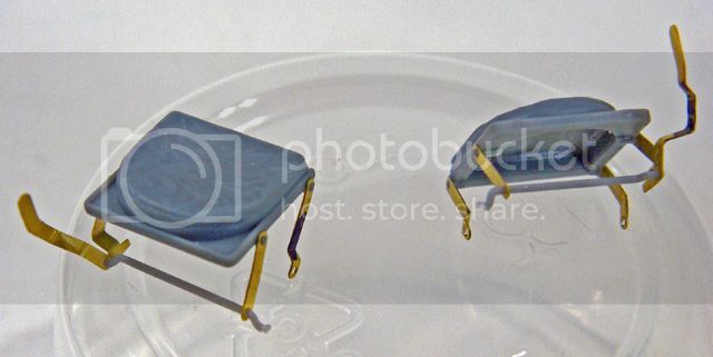
The seats were quite challenging, and I had to clean-up and dry-fit the lower hull sides in order to get the kit PE adjusting levers folded and fit. These levers will actually be trapped into a plastic crescent-shaped brackets on each lower hull side. However, I wanted to leave the sides off until later so that I could access the floor.
The seat floor hing-mount pins were short molded in my kit, so I replaced them with cylinders punched from sheet styrene that will hold PE the seat frames.
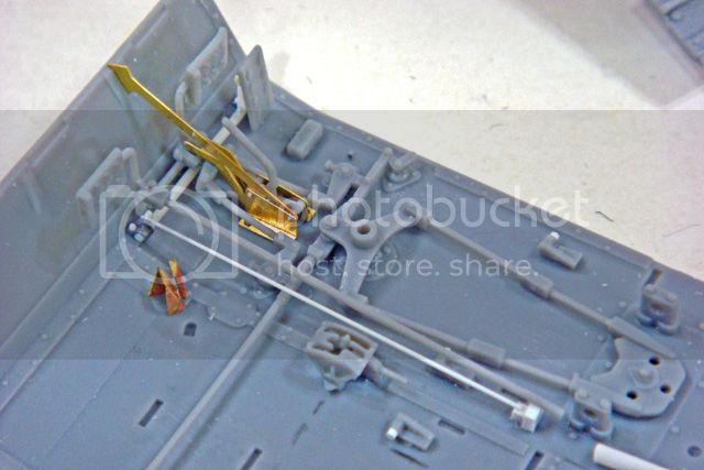
After building the seats, I finished up the steering and braking linkages. I have added the throttle pedal crank and linkage (white styrene).
The PE parking brake assembly has to be fit at the same time as the brake pedal linkages. Note the PE parking brake linkage also attaches to this same pedal.
Riich would have you add the hull side walls and then build the steering and brake linkages, add the engine and compartment, and then complete the driver / gunner forward compartment. This is just possible, as Terry demonstrated in his review, but it really makes no sense. It also makes any interior painting very difficult, if not impossible.
Also, I intend to add all three crew figures. In order to fit the crew into the vehicle, they must be assembled at the same time as the carrier or it will be impossible to get them to fit later.
With this in mind, I've skipped all over the instructions to build sub-assemblies and finish the hull floor and much of the front crew compartment first.
After the engine, I added the floor hing-mounts for the front seats and then built the seats.

The seats were quite challenging, and I had to clean-up and dry-fit the lower hull sides in order to get the kit PE adjusting levers folded and fit. These levers will actually be trapped into a plastic crescent-shaped brackets on each lower hull side. However, I wanted to leave the sides off until later so that I could access the floor.
The seat floor hing-mount pins were short molded in my kit, so I replaced them with cylinders punched from sheet styrene that will hold PE the seat frames.

After building the seats, I finished up the steering and braking linkages. I have added the throttle pedal crank and linkage (white styrene).
The PE parking brake assembly has to be fit at the same time as the brake pedal linkages. Note the PE parking brake linkage also attaches to this same pedal.
SdAufKla

Joined: May 07, 2010
KitMaker: 2,238 posts
Armorama: 2,158 posts

Posted: Saturday, August 03, 2013 - 12:31 PM UTC
Ok, so all this has been building up (no pun intended) to getting the front driver-gunner crew compartment organized so that I can pose / fit the driver figure.
Here's the compartment with the firewall and seats now dry-fitted:
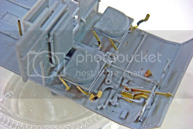
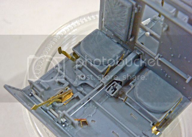
The fact that all of this is pretty much just press-fit together and holds is a testament to the precision of the fit on the kit parts.
I have found a few short-molded attachment pins and/or alignment holes that are too small, but once these have been adjusted, the actual parts fit has been most excellent.
The instruction assembly sequence is crazy, and I particularly could have used front and rear elevation views of the seats and some folding measurements for the seat PE. However, with these few exceptions, the kit has been very well designed.
To be sure, some might find the parts count a bit excessive and others will not like the fact that the kit PE must be used (no plastic alternatives are included). But I personally like the extra detail and I have no problems building PE, so for me, this kit has been very enjoyable (so far).
Here's the compartment with the firewall and seats now dry-fitted:


The fact that all of this is pretty much just press-fit together and holds is a testament to the precision of the fit on the kit parts.
I have found a few short-molded attachment pins and/or alignment holes that are too small, but once these have been adjusted, the actual parts fit has been most excellent.
The instruction assembly sequence is crazy, and I particularly could have used front and rear elevation views of the seats and some folding measurements for the seat PE. However, with these few exceptions, the kit has been very well designed.
To be sure, some might find the parts count a bit excessive and others will not like the fact that the kit PE must be used (no plastic alternatives are included). But I personally like the extra detail and I have no problems building PE, so for me, this kit has been very enjoyable (so far).
Posted: Saturday, August 03, 2013 - 02:34 PM UTC
Mike Firstly great progress on a model I cannot agree with you more about as regards kits that impress. There have been two products that have made me say wow out loud recently; the Riich Model UC is one and the other is the war reporters from Bronco Models. The figures from Bronco Impressed me because of how clean they are.
Mike if you give it a little while and take it slow Bill Cross can join you in your build as I posted this kit off to him last week and it arrived yesterday.
Mike if you give it a little while and take it slow Bill Cross can join you in your build as I posted this kit off to him last week and it arrived yesterday.
Posted: Saturday, August 03, 2013 - 07:19 PM UTC
Hi Mike,
Excellent work, following with interest.
Al

Excellent work, following with interest.
Al


Keef1648

Joined: January 23, 2008
KitMaker: 1,240 posts
Armorama: 1,192 posts

Posted: Sunday, August 04, 2013 - 01:03 AM UTC
As usual, nice work Mike.
Nothing really is built totally 'out of the box' when it comes from your work space and this one is no different.
Nice to see and hear that you were able to find and sort out all the couplings that were not in the instructions....
I understand the driver figure will need a major operation in order to get him 'sqwershed' into his position.
I look forward to seeing this at our meeting if possible.
Keith.
Nothing really is built totally 'out of the box' when it comes from your work space and this one is no different.
Nice to see and hear that you were able to find and sort out all the couplings that were not in the instructions....
I understand the driver figure will need a major operation in order to get him 'sqwershed'
 into his position.
I look forward to seeing this at our meeting if possible.
Keith.

SdAufKla

Joined: May 07, 2010
KitMaker: 2,238 posts
Armorama: 2,158 posts

Posted: Sunday, August 04, 2013 - 02:38 AM UTC
Thanks for the early replies, guys.
@ Darren: I'll be looking forward to Bill's build, but as slow as I am, there's no worries that I'll even be close to finished when he starts. I'm pretty sure that both builds will be here concurrently.
@ Alan: Thanks, I hope the build will continue to hold your interest.
@ Keith: You're right my friend. I guess "out of the box" takes on a different definition on my workbench!
So, on to the driver figure.
The figures would seem to be the exception to the excellent design and fit of the rest of the kit. My advice is to build and fit them at the same time as the main kit. Perhaps the other two figures will be a better fit to the kit, but as for the driver...
I simply can't believe that the sculpter made any effort to actually fit the figure to the space. He's not even close.
To illustrate what I've done, here're a couple of in-progress pictures:
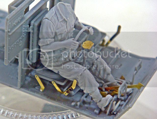

I started with the lower torso and legs. After cleaning these up and gluing them together, it was obvious that a lot of work was necessary to get the driver to fit.
I cut the legs apart at the knees and feet and then fit the driver's bottom and lower back to sit flat on his seat. I then angled the lower legs to bend quite a lot at the knees and finally added the feet back sitting on the floor (left foot) and on the throttle pedal (right foot).
Next I added the upper torso and temporarily attached the steering wheel to its column. I then dry-fit fit the steering wheel and column so that the column and wheel were vertical. This required quite a bit of grinding on the figure's upper thighs and lap area to create clearance room for the steering wheel and column.
Next I added the arms with the hands dry-fit to the steering wheel. That's the point shown in the photos above.
My plan is now to cut the figure's arms off at the rolled-up sleeves. I will then cut the fingers off of the hands leaving the palms.
Next, I will make the permanent glue bond with the steering wheel and column and allow that to dry hard. Once the steering wheel and column have dried hard, I will glue the palms of the hands to the wheel and while those joints are still soft, I will temporarily reattach the arms to the body.
The driver with his arms and the steering wheel-column assembly will be dry-fit back into the compartment and the hand-steering wheel joints allowed to dry hard.
I'll then detach the temp joints with the arms to the sleeves leaving me with two major driver sub-assemblies - the body and legs and the arms and steering wheel. I'll use epoxy putty to make new fingers gripping the steering wheel and clean up all the joints from re-posing the driver. I'll use a Hornet resin head as a replacement for the kit figure head.
Hopefully, I'll be able to paint the figure in three parts - head, body and legs, arms and steering wheel - and then bring them all together in the finished driver's compartment during final assembly...
Well, that's may plan. We'll see how it works.
Happy modeling!
@ Darren: I'll be looking forward to Bill's build, but as slow as I am, there's no worries that I'll even be close to finished when he starts. I'm pretty sure that both builds will be here concurrently.
@ Alan: Thanks, I hope the build will continue to hold your interest.
@ Keith: You're right my friend. I guess "out of the box" takes on a different definition on my workbench!
So, on to the driver figure.
The figures would seem to be the exception to the excellent design and fit of the rest of the kit. My advice is to build and fit them at the same time as the main kit. Perhaps the other two figures will be a better fit to the kit, but as for the driver...
I simply can't believe that the sculpter made any effort to actually fit the figure to the space. He's not even close.
To illustrate what I've done, here're a couple of in-progress pictures:


I started with the lower torso and legs. After cleaning these up and gluing them together, it was obvious that a lot of work was necessary to get the driver to fit.
I cut the legs apart at the knees and feet and then fit the driver's bottom and lower back to sit flat on his seat. I then angled the lower legs to bend quite a lot at the knees and finally added the feet back sitting on the floor (left foot) and on the throttle pedal (right foot).
Next I added the upper torso and temporarily attached the steering wheel to its column. I then dry-fit fit the steering wheel and column so that the column and wheel were vertical. This required quite a bit of grinding on the figure's upper thighs and lap area to create clearance room for the steering wheel and column.
Next I added the arms with the hands dry-fit to the steering wheel. That's the point shown in the photos above.
My plan is now to cut the figure's arms off at the rolled-up sleeves. I will then cut the fingers off of the hands leaving the palms.
Next, I will make the permanent glue bond with the steering wheel and column and allow that to dry hard. Once the steering wheel and column have dried hard, I will glue the palms of the hands to the wheel and while those joints are still soft, I will temporarily reattach the arms to the body.
The driver with his arms and the steering wheel-column assembly will be dry-fit back into the compartment and the hand-steering wheel joints allowed to dry hard.
I'll then detach the temp joints with the arms to the sleeves leaving me with two major driver sub-assemblies - the body and legs and the arms and steering wheel. I'll use epoxy putty to make new fingers gripping the steering wheel and clean up all the joints from re-posing the driver. I'll use a Hornet resin head as a replacement for the kit figure head.
Hopefully, I'll be able to paint the figure in three parts - head, body and legs, arms and steering wheel - and then bring them all together in the finished driver's compartment during final assembly...
Well, that's may plan. We'll see how it works.
Happy modeling!
SdAufKla

Joined: May 07, 2010
KitMaker: 2,238 posts
Armorama: 2,158 posts

Posted: Sunday, August 04, 2013 - 02:47 AM UTC
Ah! I almost forgot one last photo.
This picture shows all the above dry-fitted components and sub-assemblies disassembled. I took it after I removed the driver as posed in the last photos to show how I'm approaching the construction and finishing.
Like I mentioned, Terry Ashley suggested that the kit essentially be built from the inside out, and that's what I'm doing.
This will allow me to finish and paint all of these interior parts, assembling as I paint and work my way from the inside of the carrier to the outside.

Again, the fact that all of these parts and sub-assemblies can be built and simply dry-fit / press-fit together to test assembly and allow separate finishing is a testament to how well the basic parts fit really is.
With the exceptions of the instructions and figures, Riich has done a very commendable job with the engineering of this kit.
This picture shows all the above dry-fitted components and sub-assemblies disassembled. I took it after I removed the driver as posed in the last photos to show how I'm approaching the construction and finishing.
Like I mentioned, Terry Ashley suggested that the kit essentially be built from the inside out, and that's what I'm doing.
This will allow me to finish and paint all of these interior parts, assembling as I paint and work my way from the inside of the carrier to the outside.

Again, the fact that all of these parts and sub-assemblies can be built and simply dry-fit / press-fit together to test assembly and allow separate finishing is a testament to how well the basic parts fit really is.
With the exceptions of the instructions and figures, Riich has done a very commendable job with the engineering of this kit.
jrutman

Joined: April 10, 2011
KitMaker: 7,941 posts
Armorama: 7,934 posts

Posted: Sunday, August 04, 2013 - 03:15 AM UTC
Mike,
Nice to see the smadge starting another little gem. Nice start with all of the teeny tiny bits.
I just went through this with the driver for my 251 build,not even in the same ball park with the fit.
J
Nice to see the smadge starting another little gem. Nice start with all of the teeny tiny bits.
I just went through this with the driver for my 251 build,not even in the same ball park with the fit.
J
dvarettoni

Joined: September 28, 2005
KitMaker: 778 posts
Armorama: 763 posts

Posted: Sunday, August 04, 2013 - 03:49 AM UTC
master mike !!!!! another great build i would love to see you do a realy oob build i don't think that you gould do it !!!! lol on the airbursh front still could not get to work so i'm going to send it back no monday got to love Badger can't wait to see this on e at the meeting
dave

dave


Emeritus

Joined: March 30, 2004
KitMaker: 2,845 posts
Armorama: 808 posts

Posted: Sunday, August 04, 2013 - 05:09 AM UTC
Very nice work! 
Seems that to say the Riich kit is lightyears ahead the old Tamiya kits is quite an understatement.
I've always liked the UC, this one looks like a must-have.

Seems that to say the Riich kit is lightyears ahead the old Tamiya kits is quite an understatement.
I've always liked the UC, this one looks like a must-have.
SdAufKla

Joined: May 07, 2010
KitMaker: 2,238 posts
Armorama: 2,158 posts

Posted: Sunday, August 04, 2013 - 09:26 AM UTC
Well, after a couple of happy hours at the workbench cleaning up the driver figure, I moved on to a couple of small engine details.
The shifter-transmission linkage is an unusual affair. I was quite puzzled about how it could have worked since Riich doesn't provide the linkage parts. After some research spent looking at restored carriers and carriers undergoing restoration, I finally found a couple of pictures that showed the missing details.
The Riich kit part G1 is the inverted transmission shift lever. It needs to be extended about 4 mm, thickened up a bit with a socket drilled into the bottom end.
What's missing from the kit is the shifter linkage bar that runs diagonally under the engine and then extends upwards in a J-bend. This J-shaped part is tapered and terminates with a ball that fits into the socket on the inverted transmission shift lever.

In this photo, the inverted transmission shift lever is the thick, green-colored part (G1) and the J-shaped shift linkage is obviously the white styrene part.
I remade this part today as I wasn't satisfied with my initial attempt and the above photo shows the new part. There are two rubber (leather or canvas) boots that fit on the shift linkage tube on either side of the floor mounting bushing if you're of a mind to add even more details.
(I left the boots off of mine - Chalk it up to poor maintenance by the RCEME mechanics. Maybe they couldn't get the spare parts?)
Another engine detail missing from the kit is what I assume to be the engine oil cooler manifold on the top left rear of the bell housing. Research showed several minor variations in the design of this part, and I will eventually add the two hoses that run from the manifold to the ends of the oil cooler (kit part G11) located forward of the radiator.
Note that the oil cooler, part G11, is a pipe with sheet metal cooling fins all along its length. The restored examples all appear to be bare metal in color. This kit part was the most difficult so far to clean up while preserving the cooling fin details.
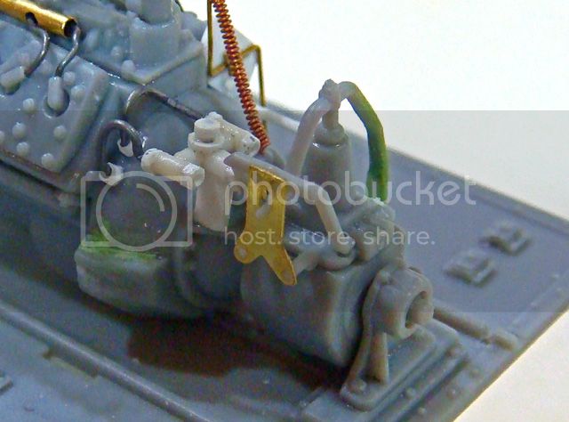
BTW, the disk on the top of the manifold is, as far as I can tell, either the oil pressure sender or perhaps an oil temp sender and will get wired up after the engine is painted.
'Til next time, happy modeling!
The shifter-transmission linkage is an unusual affair. I was quite puzzled about how it could have worked since Riich doesn't provide the linkage parts. After some research spent looking at restored carriers and carriers undergoing restoration, I finally found a couple of pictures that showed the missing details.
The Riich kit part G1 is the inverted transmission shift lever. It needs to be extended about 4 mm, thickened up a bit with a socket drilled into the bottom end.
What's missing from the kit is the shifter linkage bar that runs diagonally under the engine and then extends upwards in a J-bend. This J-shaped part is tapered and terminates with a ball that fits into the socket on the inverted transmission shift lever.

In this photo, the inverted transmission shift lever is the thick, green-colored part (G1) and the J-shaped shift linkage is obviously the white styrene part.
I remade this part today as I wasn't satisfied with my initial attempt and the above photo shows the new part. There are two rubber (leather or canvas) boots that fit on the shift linkage tube on either side of the floor mounting bushing if you're of a mind to add even more details.
(I left the boots off of mine - Chalk it up to poor maintenance by the RCEME mechanics. Maybe they couldn't get the spare parts?)
Another engine detail missing from the kit is what I assume to be the engine oil cooler manifold on the top left rear of the bell housing. Research showed several minor variations in the design of this part, and I will eventually add the two hoses that run from the manifold to the ends of the oil cooler (kit part G11) located forward of the radiator.
Note that the oil cooler, part G11, is a pipe with sheet metal cooling fins all along its length. The restored examples all appear to be bare metal in color. This kit part was the most difficult so far to clean up while preserving the cooling fin details.

BTW, the disk on the top of the manifold is, as far as I can tell, either the oil pressure sender or perhaps an oil temp sender and will get wired up after the engine is painted.
'Til next time, happy modeling!
jet

Joined: December 30, 2002
KitMaker: 306 posts
Armorama: 295 posts

Posted: Sunday, August 04, 2013 - 02:04 PM UTC
Excellent blogging!
I have a few walkarounds
http://www.armourworkshop.ca/gallery/album.php?album_id=247
http://www.armourworkshop.ca/gallery/album.php?album_id=302
(plus about 10 others I need to get sorted and posted...)

I have a few walkarounds
http://www.armourworkshop.ca/gallery/album.php?album_id=247
http://www.armourworkshop.ca/gallery/album.php?album_id=302
(plus about 10 others I need to get sorted and posted...)

panamadan

Joined: July 20, 2004
KitMaker: 1,513 posts
Armorama: 1,449 posts

Posted: Sunday, August 04, 2013 - 02:12 PM UTC
Glad to see you back in action Mike.
Dan
Dan

Posted: Sunday, August 04, 2013 - 07:17 PM UTC
WOW! The detail of this kit is impressive, and your scratch additions really bring it to the next level. Very impressive!
Cheers!
Stefan
Cheers!
Stefan
knewton


Joined: June 19, 2013
KitMaker: 1,217 posts
Armorama: 1,092 posts
Posted: Sunday, August 04, 2013 - 07:44 PM UTC
Great build blog, thank you. I had no interest in the UC until this kit came out, and picked up one when in Hong Kong just because it is so good. I will be using this as a guide when I commence mine.
After seeing one in the Solomon Islands when deployed with RAMSI PPF, it really is a tiny vehicle! Good luck fitting three guys in!
Kylie
After seeing one in the Solomon Islands when deployed with RAMSI PPF, it really is a tiny vehicle! Good luck fitting three guys in!
Kylie
SdAufKla

Joined: May 07, 2010
KitMaker: 2,238 posts
Armorama: 2,158 posts

Posted: Monday, August 05, 2013 - 11:41 AM UTC
Progress today was measured in millimeters, but everything has to be done, no matter how small.
@ James: Thanks for the links to the photo galleries. As you'll see below, they were very helpful. (The registration process for Armour Workshop website is easy and fast for anyone else who might be reluctant. Well worth the small effort!)
@ Dan: It's good to be back in the saddle again!
@ Stefan: Thank you for the kind words.
@ Kylie: I'm gaining an all new appreciation of the trials and tribulation of the poor sods who had to operate and fight this thing.
I actually now think that the driver would most usually sit facing slightly to his left with his legs spread quite a bit rather than straight forward, at least this looks like the most comfortable position. Legs to the front might have been better for a road march or a change of position, but to reach the clutch pedal the left leg has to reach over way to the driver's left. Anyways...
Hopefully all three of the kit figures can be made to fit. We'll see...
Today I worked on the driver some more, but no pictures since it's mostly just filing, sanding and buffing at this point. I'm sticking to the process I outlined earlier and it seems to be working. I'll post pics when he's ready for primer and painting.
After the driver, I corrected an error that has been pointned out to me in the kit - the opening for the radiator should be a regular rectangle with radiused corners rather than the upward tapering trapezoid reproduced by Riich.
Paul Owen mentions and makes this change in his build blog on Track-Link:
Track-Link::Riich Universal Carrier Build Blog
However, I confess that I was a bit skeptical give how nice the rest of the kit has been and chalked up the difference to a likely manufacturing variation (it still might be). But, right after I started this blog, another well respected modeler PM'ed me with the same observation, so after checking all my references, to include the photo galleries linked by James (above), I decided that the rectangular opening was at least common.
So, how to make the change?
Here are two photos showing the finished change:
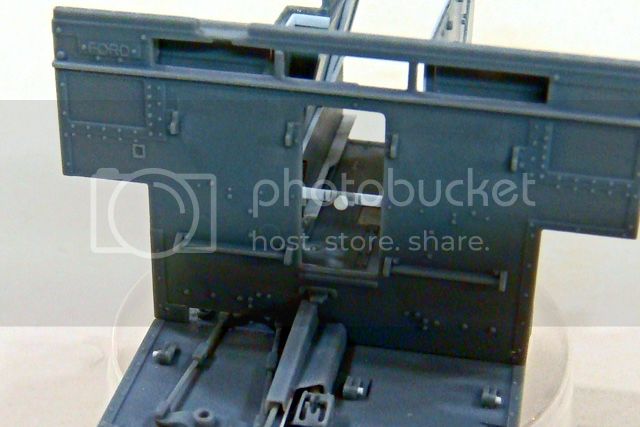
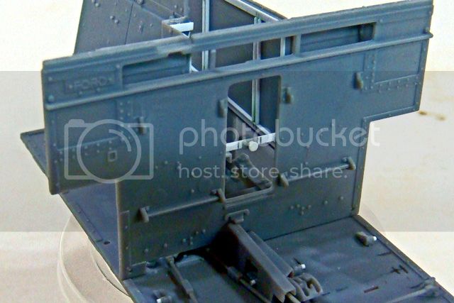
The rectangular opening appeared to me in the reference photos to be about the same width as the kit opening at its bottom, so I used a pair of dividers set from the vertical side edges of the firewall and the edge of the bottom of the kit opening to scribe witness lines from the lower corners upwards on each side of the kits' opening.
I then set the dividers for the distance from the top edge of the firewall and the top edge of the kit's opening and scribed lines extending the kit opening to the sides meeting the earlier vertical lines.
I measured the radius of lower kit opening corners using my drill bits until I found a match (~.030 dia). The, using the matching drill bit as a broach (pushing vice twisting), I opened the new top corners until the edges of the radius met the top and side scribed lines.
The, using a brand new no. 11 X-acto blade in my knife, I carefully carved the new opening to match the side and top scribed lines. I cleaned up the edges a bit with regular files and a Flexi-file and had the new rectangular opening.
I replaced the cross brace with a strip of .010x.040 styrene strip, and added the kit knob and mount back after sanding away the excess plastic on its reverse. I added the rivets / bolts on the backside with .018 dia x .010 punched disks.
This was a quick and easy correction / change, and I appreciate Ron (who PM'ed me) sharing his research findings.
One more note: Paul Owen removed the "Ford" placard from his kit's firewall (located to the rear of the driver's head area) because he couldn't find a match in his references, but several of the photos in one of James' galleries clearly show a "Ford Canada" placard in the same location, so I've left this detail on my kit.
(Thanks again, James!)
@ James: Thanks for the links to the photo galleries. As you'll see below, they were very helpful. (The registration process for Armour Workshop website is easy and fast for anyone else who might be reluctant. Well worth the small effort!)
@ Dan: It's good to be back in the saddle again!
@ Stefan: Thank you for the kind words.
@ Kylie: I'm gaining an all new appreciation of the trials and tribulation of the poor sods who had to operate and fight this thing.
I actually now think that the driver would most usually sit facing slightly to his left with his legs spread quite a bit rather than straight forward, at least this looks like the most comfortable position. Legs to the front might have been better for a road march or a change of position, but to reach the clutch pedal the left leg has to reach over way to the driver's left. Anyways...
Hopefully all three of the kit figures can be made to fit. We'll see...
Today I worked on the driver some more, but no pictures since it's mostly just filing, sanding and buffing at this point. I'm sticking to the process I outlined earlier and it seems to be working. I'll post pics when he's ready for primer and painting.
After the driver, I corrected an error that has been pointned out to me in the kit - the opening for the radiator should be a regular rectangle with radiused corners rather than the upward tapering trapezoid reproduced by Riich.
Paul Owen mentions and makes this change in his build blog on Track-Link:
Track-Link::Riich Universal Carrier Build Blog
However, I confess that I was a bit skeptical give how nice the rest of the kit has been and chalked up the difference to a likely manufacturing variation (it still might be). But, right after I started this blog, another well respected modeler PM'ed me with the same observation, so after checking all my references, to include the photo galleries linked by James (above), I decided that the rectangular opening was at least common.
So, how to make the change?
Here are two photos showing the finished change:


The rectangular opening appeared to me in the reference photos to be about the same width as the kit opening at its bottom, so I used a pair of dividers set from the vertical side edges of the firewall and the edge of the bottom of the kit opening to scribe witness lines from the lower corners upwards on each side of the kits' opening.
I then set the dividers for the distance from the top edge of the firewall and the top edge of the kit's opening and scribed lines extending the kit opening to the sides meeting the earlier vertical lines.
I measured the radius of lower kit opening corners using my drill bits until I found a match (~.030 dia). The, using the matching drill bit as a broach (pushing vice twisting), I opened the new top corners until the edges of the radius met the top and side scribed lines.
The, using a brand new no. 11 X-acto blade in my knife, I carefully carved the new opening to match the side and top scribed lines. I cleaned up the edges a bit with regular files and a Flexi-file and had the new rectangular opening.
I replaced the cross brace with a strip of .010x.040 styrene strip, and added the kit knob and mount back after sanding away the excess plastic on its reverse. I added the rivets / bolts on the backside with .018 dia x .010 punched disks.
This was a quick and easy correction / change, and I appreciate Ron (who PM'ed me) sharing his research findings.
One more note: Paul Owen removed the "Ford" placard from his kit's firewall (located to the rear of the driver's head area) because he couldn't find a match in his references, but several of the photos in one of James' galleries clearly show a "Ford Canada" placard in the same location, so I've left this detail on my kit.
(Thanks again, James!)
SdAufKla

Joined: May 07, 2010
KitMaker: 2,238 posts
Armorama: 2,158 posts

Posted: Monday, August 05, 2013 - 12:00 PM UTC
Because I'm going to show off my kit's engine, I wanted to add some detail to the insides of the engine compartment walls.
Curiously, Riich didn't add any interior details to the side walls of the compartment. I say curiously since all the other surfaces are detailed.
Anyways, on the actual vehicle, the engine compartment is made of a frame of welded, bolted, riveted angle, U-channel and flat straps covered with removable sheet metal covers.
Because of the thickness of the kit parts, it's not possible to replicate all of the dimensions of the actual compartment frame. If this was done, the engine and walls would interfere with each other. It might be possible to thin down the kit side walls and then add the frame.
However, because of the restricted view that I'm expecting, the interior of the side walls can only be viewed at a angle from above, so all that's needed are additions that add the horizontal and vertical lines that will be visible from that direction and angle.
Here are my engine compartment walls:
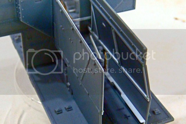
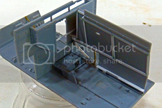
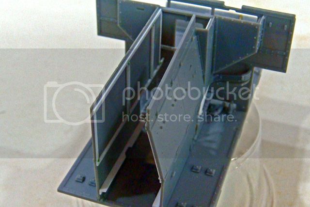
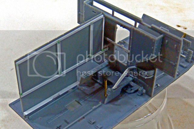
The prototype carrier has a pair of longitudinal channel braces that run the full length of each side of the compartment along the floor. I replicated these with L-angle strips.
The interior side frame members were made with .010x.040, .010x.030 and .010x.020 styrene strips. I did notch along the beveled top edges of the compartment side panels using a small cutter in my moto-tool, files and sandpaper.
The final results are not a perfect match for the prototype, but they look "right" and because I did use the locations of the prototype's frame members as a guide, it's actually pretty close (given the compromises between scale-sized sheet metal and injection molded plastic).
Happy modeling,
Curiously, Riich didn't add any interior details to the side walls of the compartment. I say curiously since all the other surfaces are detailed.
Anyways, on the actual vehicle, the engine compartment is made of a frame of welded, bolted, riveted angle, U-channel and flat straps covered with removable sheet metal covers.
Because of the thickness of the kit parts, it's not possible to replicate all of the dimensions of the actual compartment frame. If this was done, the engine and walls would interfere with each other. It might be possible to thin down the kit side walls and then add the frame.
However, because of the restricted view that I'm expecting, the interior of the side walls can only be viewed at a angle from above, so all that's needed are additions that add the horizontal and vertical lines that will be visible from that direction and angle.
Here are my engine compartment walls:


The prototype carrier has a pair of longitudinal channel braces that run the full length of each side of the compartment along the floor. I replicated these with L-angle strips.
The interior side frame members were made with .010x.040, .010x.030 and .010x.020 styrene strips. I did notch along the beveled top edges of the compartment side panels using a small cutter in my moto-tool, files and sandpaper.
The final results are not a perfect match for the prototype, but they look "right" and because I did use the locations of the prototype's frame members as a guide, it's actually pretty close (given the compromises between scale-sized sheet metal and injection molded plastic).
Happy modeling,
chefchris

Joined: February 06, 2006
KitMaker: 1,544 posts
Armorama: 1,464 posts

Posted: Monday, August 05, 2013 - 12:38 PM UTC
Doesn't look all that simple.... 


The kit looks impressive for its size and price.
I love it!


The kit looks impressive for its size and price.
I love it!

Posted: Tuesday, August 06, 2013 - 09:25 PM UTC
Excellent build log Mike. I enjoy reading these and the results so far are fantastic. 

Keef1648

Joined: January 23, 2008
KitMaker: 1,240 posts
Armorama: 1,192 posts

Posted: Tuesday, August 06, 2013 - 11:24 PM UTC
Quoted Text
After a hard time finding my model-building mojo following my last marathon project, I've finally decided on doing a "simple" out of the box build, the Riich Models RV35011 "Universal Carrier, Mk. I."
Knowing Mike quite well, as he is the President of our AMPS club branch, what he really meant to say was,
> "I will 'simply' lift it out of the box and build it my way"..


As usual Mike, stirling work and first class build log.
Keith.

SdAufKla

Joined: May 07, 2010
KitMaker: 2,238 posts
Armorama: 2,158 posts

Posted: Wednesday, August 07, 2013 - 01:20 AM UTC
@ Chris: I can see your point!  I guess "simple" is a relative term...
@ Frank: Thanks for the kind words. I enjoy sharing the work and hope that the blog won't become too tedious.
@ Keith: Oh, you funny man! You know me too well!
Hey, no after-market resin; no AM PE; no AM gun barrel; no AM link-to-link track; no figures besides the kit figgies
(Hornet heads don't count! They're like glue - ya can't build plastic figures without 'em!)
So, this is "out-of-the-box" in my workroom!
In my defense: I'm not spending the national treasury on new reference materials; I'm not writing a book of construction notes; and I'm not kit-bashing a half-dozen odds-'n-sods into something that resembles the prototype because no decent kit of it exists. I'm just producing a build of the subject, more or less, as the kit maker intended, welll... sort of...
I MIGHT even gets this finished before 2014!
Now, what's a little styrene strip, brass tubing and wire solder between friends? Really... It's just a little "seasoning to taste" now.
Besides, who just gave me HIS recipe for "resin kit builds"?
"Pour a pint of glue in the box, stir (not shaken), allow to sit over night, turn box over, paint two contrasting colors, and... voila!"


See ya next week at the meeting. I'm sure the guys will all enjoy your resin kit "cooking" demo!
Cheers!


 I guess "simple" is a relative term...
@ Frank: Thanks for the kind words. I enjoy sharing the work and hope that the blog won't become too tedious.
@ Keith: Oh, you funny man!
 You know me too well!
Hey, no after-market resin; no AM PE; no AM gun barrel; no AM link-to-link track; no figures besides the kit figgies
(Hornet heads don't count! They're like glue - ya can't build plastic figures without 'em!)
So, this is "out-of-the-box" in my workroom!
In my defense: I'm not spending the national treasury on new reference materials; I'm not writing a book of construction notes; and I'm not kit-bashing a half-dozen odds-'n-sods into something that resembles the prototype because no decent kit of it exists. I'm just producing a build of the subject, more or less, as the kit maker intended, welll... sort of...

I MIGHT even gets this finished before 2014!
Now, what's a little styrene strip, brass tubing and wire solder between friends? Really... It's just a little "seasoning to taste" now.
Besides, who just gave me HIS recipe for "resin kit builds"?
"Pour a pint of glue in the box, stir (not shaken), allow to sit over night, turn box over, paint two contrasting colors, and... voila!"


See ya next week at the meeting. I'm sure the guys will all enjoy your resin kit "cooking" demo!
Cheers!


jrutman

Joined: April 10, 2011
KitMaker: 7,941 posts
Armorama: 7,934 posts

Posted: Wednesday, August 07, 2013 - 01:52 AM UTC
I was also kind of puzzled when you said that this would be "out of the box" because one,you never build like that and two,on your very first post you went "out of the box".
Either way,it's looking good as usual with your usual attention to detail and very clean technique in play.
J
Either way,it's looking good as usual with your usual attention to detail and very clean technique in play.
J
pseudorealityx

Joined: January 31, 2010
KitMaker: 2,191 posts
Armorama: 1,814 posts

Posted: Wednesday, August 07, 2013 - 02:14 AM UTC
Very impressive Mike. I'm currently suffering my own period of burn-out and haven't sat at the bench for about a month. This is inspiring though. Keep it up.
 |


