Hi all,

A brief update on the Paris gun build. Still working on the base, adding details which don't look like much but require a lot of time, especially with so few dimensions to work with. Looking at the thing on my work table, I wondered if I wasn't subconsciously modeling something out of Star Wars, the Millenium Falcon perhaps.
I finally worked out the traversing mechanisms which are built into the base. The low-speed traverse used gearboxes mounted between the rails in the center of the base, transmitting muscle power through a pair of drive shafts, each with two universal joints, to gears which engaged the ring gear on the fixed base. The high speed traverse mechanism was mounted on the outside of the rotating base. According to Col. Miller, with two men on each of the four cranks of the low-speed gear boxes, the gun could be easily turned to point in any direction. The high-speed traverse was mainly used during setup, to rotate the carriage 90 degrees after it was lifted off the railway trucks.
The low-speed traverse drive shafts can be seen in several photos of emplacements for the Paris gun and also the Lange Max 38 cm guns, and are truly massive for something which in the case of the Paris gun had at most 4 men turning each one. I wonder if they weren't parts originally intended for the battleships from which the 38 cm guns came. The Paris gun used electric motors to elevate the barrel to firing position, and it was lowered to horizontal for loading. Traversing was always manual. Once the direction to Paris was set, it was never changed until the gun was moved to a new location.
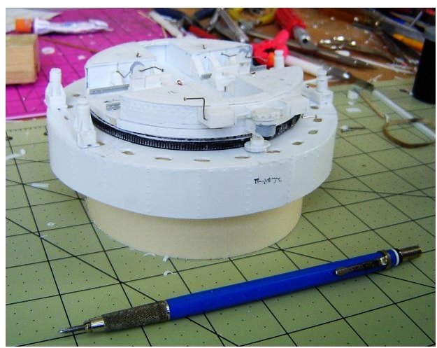
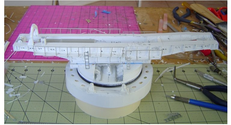
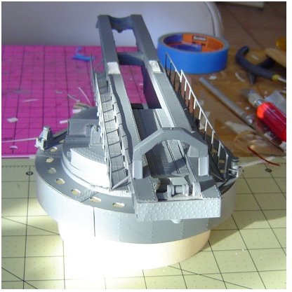
The first photo shows the rear side of the base oriented as it would be as the gun carriage was rolled onto it. The two low-speed gear boxes between the rails would not have been there when the carriage arrived, and were mounted later, after the carriage was rotated 90 degrees and lowered onto the base. The cranks were made from straight pins.
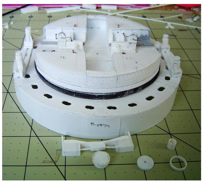
The pair of tall hydraulic jacks in the foreground have pumps at their bases and were connected through pipes to the pair of low jacks on the far side. They were used to lift the carriage off the trucks. I did make handles for the jacks but they didn't look right, and I'm trying to come up with something better. I have to keep in mind that a 1 mm diameter rod equates to 72 cm at this scale.
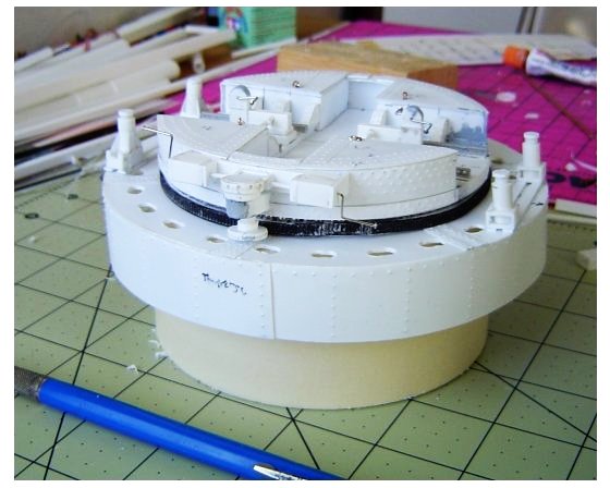
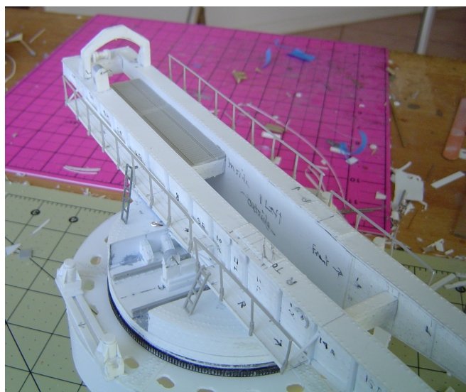
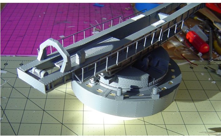
The next photo is of the opposite side of the fixed base, with the moveable base rotated 180 degrees so it is still in the same position. In this view, the low jacks are in the foreground. The drive shafts of the low-speed traversing mechanism are to the left of the gearboxes.
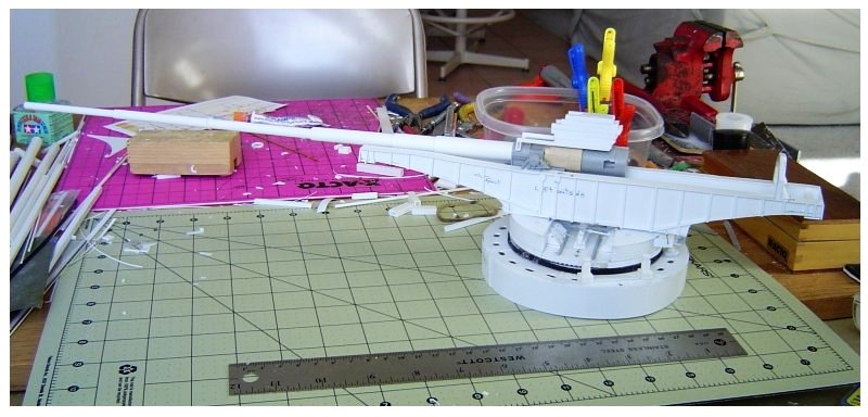
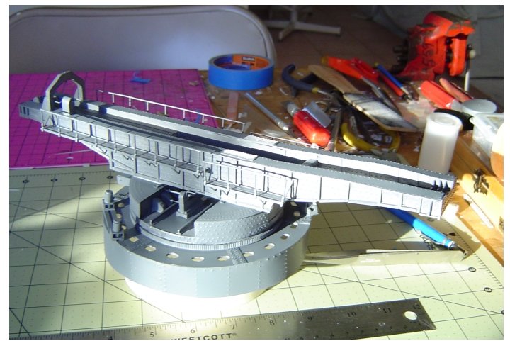
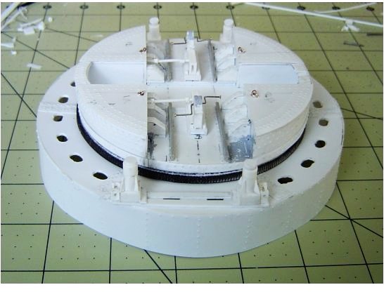
The next photo is a side view, high jacks on the left and low jacks to the right, with the gearboxes for the low-speed traverse in the middle. Parts for the yet-to-be-installed high-speed traverse are in the foreground.
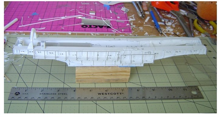
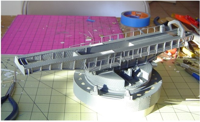
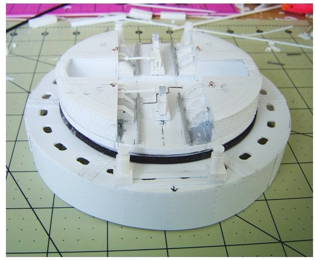
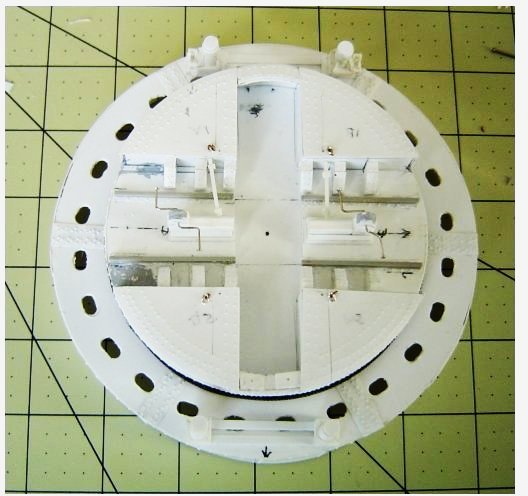
The last photo is a vertical view of the base with lifting rings installed, one in each quadrant.
Still a lot to do, but the base is nearly finished.
Cheers,

Dick