

1⁄35M103A2 Heavy Tank
18
Comments
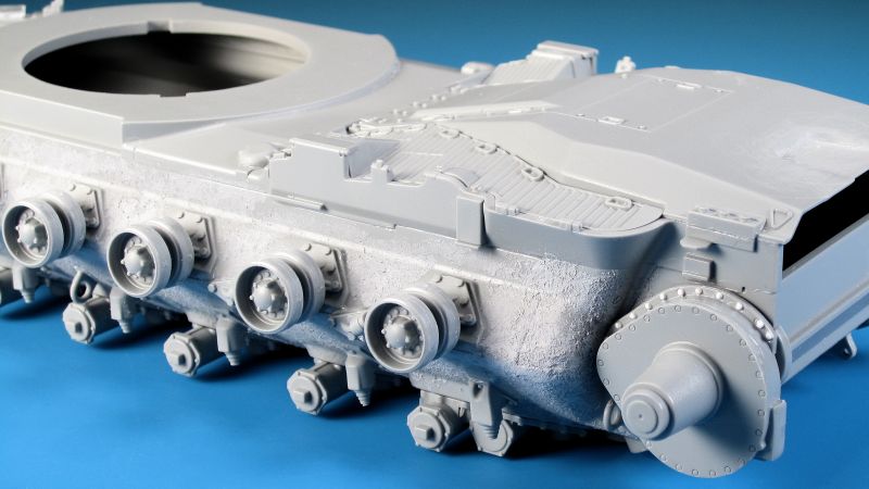
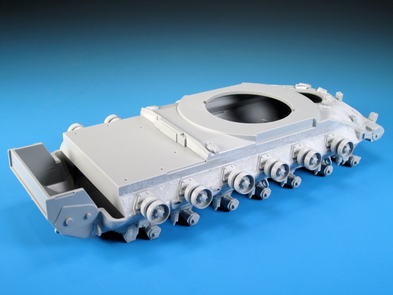
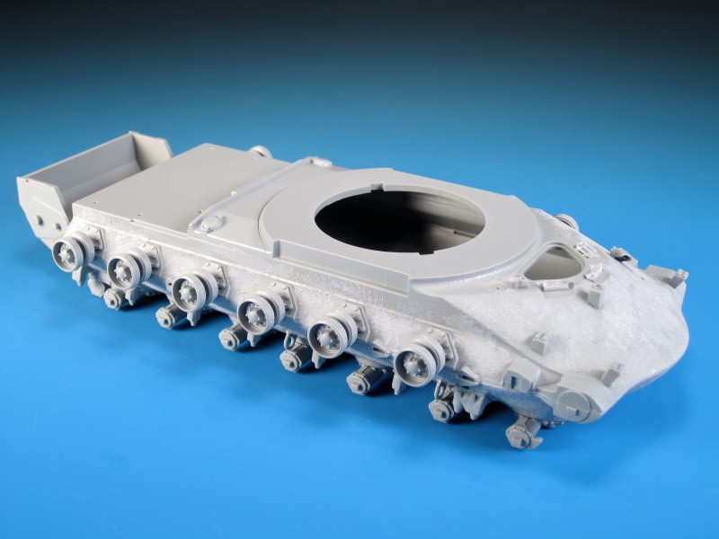
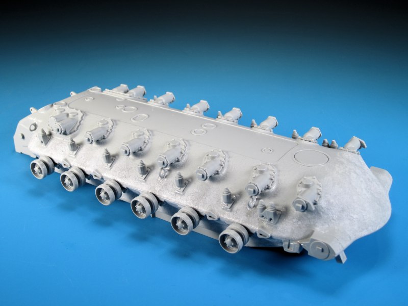
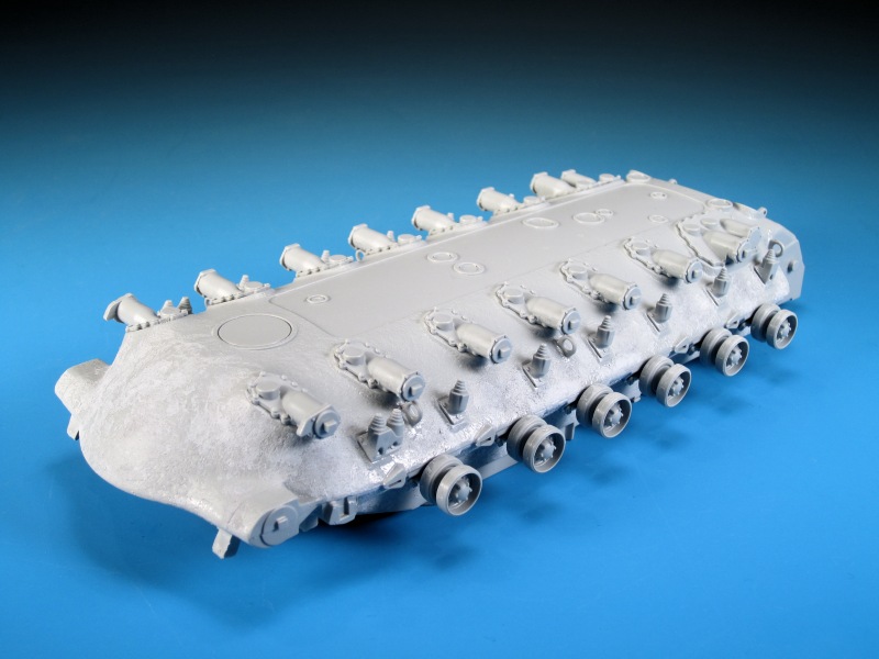
Part 1 - Hell of a Hull
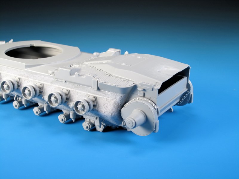
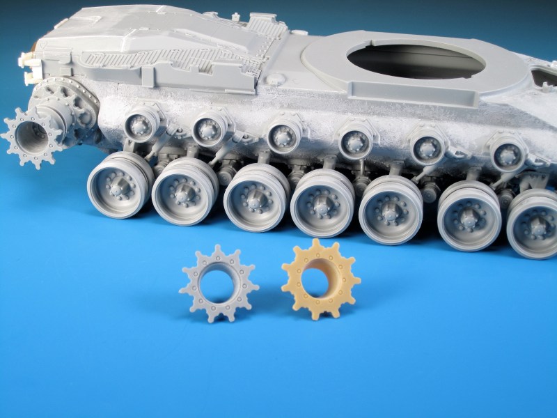
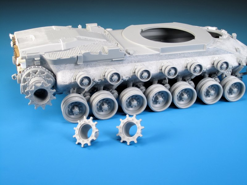
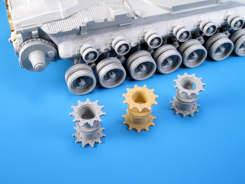
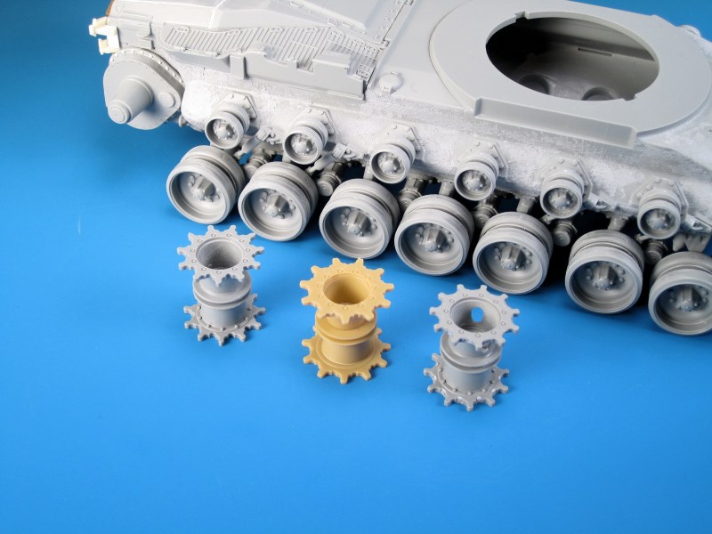
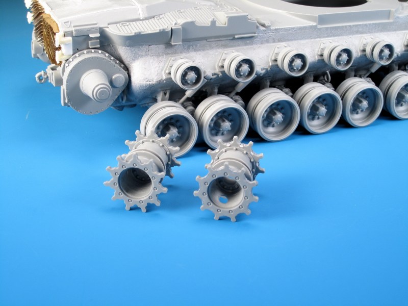
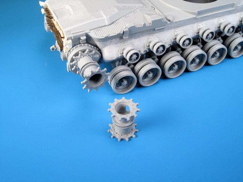
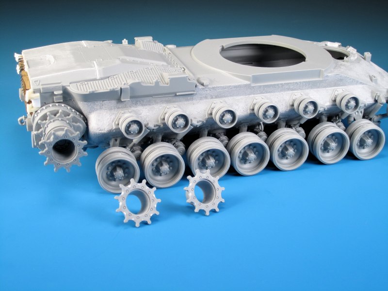
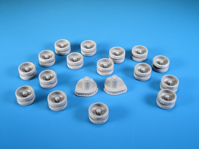
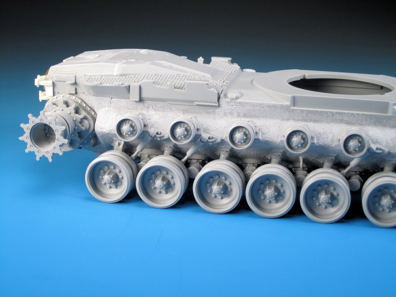
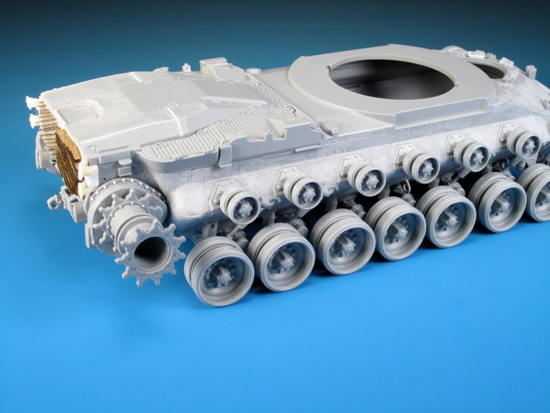
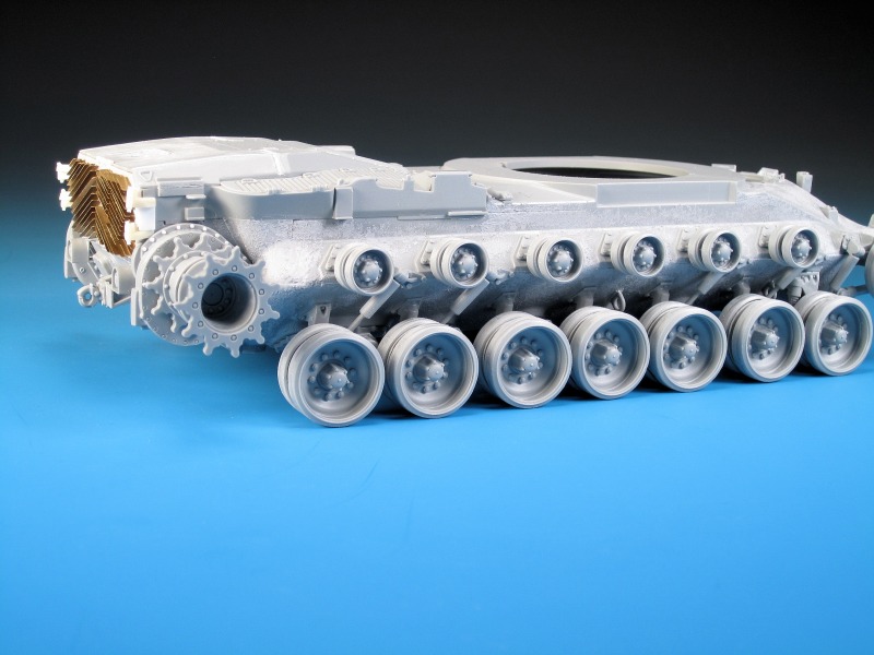
The kit hull comes in two main pieces like a big old armoured submarine sandwich! The instructions have you attach parts to the upper and lower hull halves and then glue them together after some minor drilling on the upper hull for the driver's hatch rests. There is cast texture on the upper and lower hull parts but I added greater casting texture with Mr. Surfacer 500 dabbed on with an old brush. I chose to not modify the front hull area and left the angle and curve provided in the kit parts. A great deal of cutting, hacking, sanding, and filling on the front hull area would be required in order to correct the front hull issues. I chose to show what the front hull looks like without angular modifications in order to provide the average everyday modeller with simpler options. The assembly of the road wheels is interesting with each road wheel using four components (inner hub, rear hub, and 2 x road wheel outers) to create each wheel. A lot of cutting, sanding, and gluing is needed to create the full set of road wheels and the two idler wheels. This concept of assembly is great for painting the rubber portions separately, but for me assembling each road wheel was actually simpler instead of partial assembly, priming, painting, and then more assembly. The detail extends to the back side of the road wheels where bolt details are easily visible. This is a novel concept that most model companies forego. It is ironic that Dragon included detail on the reverse side of the road wheels yet did not include so many much more visible details. On the final drive covers I noted that the outer bolt detail was recessed. It should actually be raised, and as such the old trusty hex shaped punch and die set came out to create new bolt heads. Once the final drive covers are added a small additional round access plug will be added to the inner bottom side of each part. If you are building this kit, don't get discouraged by all the road wheels on the sprues. You get extra sprues from the Dragon M48A3 Mod B kit, so you don't use all of the available road wheel parts provided. I finished off the suspension by adding the arms and shocks. This takes some careful planning, cleanup of parts, examining the instructions several times, and then only a wee bit of glue. The instructions for the final assembly of the suspension appeared weak to me. It was not clear on the placement of the shock absorbers with relation to the road wheel arms. After some careful dry fitting the light bulb came on as to how the parts should properly fit together. There are for sure some interlocking and overlapping components in the M103A2 suspension. The fit of the road wheel arms is very tight and can be dry fitted without any glue to ensure the parts sit correctly and evenly, so that all of the road wheels sit correctly on a flat surface. Add a bit of glue to each arm once you get that oh so nice flat sitting look. Attaching the road wheels for dry fitting is next to impossible. There are no poly caps in the road wheels, and the road wheel arms have just little nubs to fit into the back of the road wheels. I used tiny bits of Blu-Tack on the arm nubs in order to test fit the road wheels. The road wheels will for sure have to be glued on after base coat painting. When I examined the kit drive sprockets compared to references I noticed a few things. The first was that on production M103A2s, the M48/M60 style sprocket used on the M103A1 was replaced by the USMC with the heavier drive sprocket from the M88. The M88 sprocket has flattened sprocket teeth edges, the indents between the teeth were eliminated, mud holes were added, and there are three small holes on the outer sprocket ring. I also noticed that the two M103A1E1 (pilot versions of the M103A2) were fitted with the older M48/M60 sprockets, and the Jacques Littlefield Museum M103A2 has the older M48/M60 style sprockets. The museum M103A2 sprockets might be explained as resulting from a possible lack of M88 sprockets to make the display tank accurate. The trial vehicles likely started with the M48/M60 style sprockets and then were finalized with the M88 sprockets. The Bovington Museum M103A2 has the correct M88 sprockets installed. At the current time there are no replacement aftermarket M88 sprockets. You can source them from the AFV Club M88 kits or the Perfect Scale Models resin M50 Heavy Recovery Vehicle. Neither of these options is great due to the price of the kits and the fact that spares are not included. I looked at options for modifying or replacing the sprockets:- Option #1- Do nothing and use the Dragon Model sprockets.
- Option #2- Use M88 sprockets and modify them to fit the Dragon Model final drives.
- Option #3- Modify the Dragon Model sprockets to replicate the M88 sprockets.
About the Author


Comments


Thanks very much again Fellas! I really appreciate your positive feedback and comments.
What's next? I've got a few Leopards to get back to but as far as Cold War Heavies...a German KPz 70 and a British FV4005 are on the list.
MAR 10, 2016 - 04:01 PM
Which was more work, building the kit or writing that article? Both are a great effort. Nice to see something a little less covered here.
MAR 13, 2016 - 05:52 AM
Building the kit was for sure much more work. I'm glad you like both results!
MAR 13, 2016 - 09:55 AM

Thanks Colin...with any luck I will have it at the Alberta Open Model Contest in Edmonton at the end of May.
MAR 13, 2016 - 11:56 PM

Thanks Bob! Not nearly what you bring to the table with your amazing ships!
MAY 12, 2016 - 05:00 AM
Copyright ©2021 by Jason Bobrowich. Images and/or videos also by copyright holder unless otherwise noted. The views and opinions expressed herein are solely the views and opinions of the authors and/or contributors to this Web site and do not necessarily represent the views and/or opinions of Armorama, KitMaker Network, or Silver Star Enterrpises. All rights reserved. Originally published on: 2016-03-08 14:36:15. Unique Reads: 20561

WEB HOSTING BY


Copyright ©2021 Armorama and Kitmaker Network, a subsidiary of Silver Star Enterprises
All Rights Reserved. Please read our Conditions of Use and Privacy Policy.
All Rights Reserved. Please read our Conditions of Use and Privacy Policy.