

1⁄35M103A2 Heavy Tank
18
Comments
Part 3 - Fender Benders
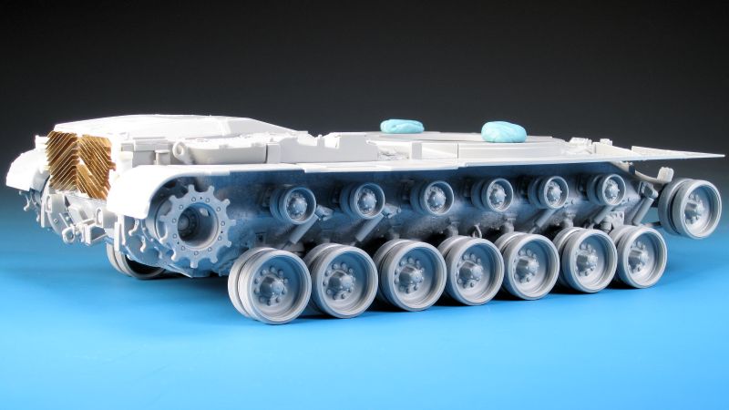
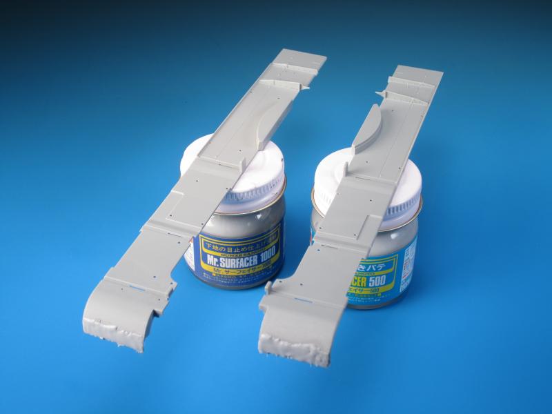
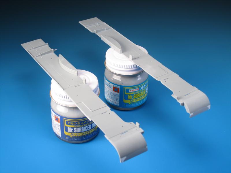
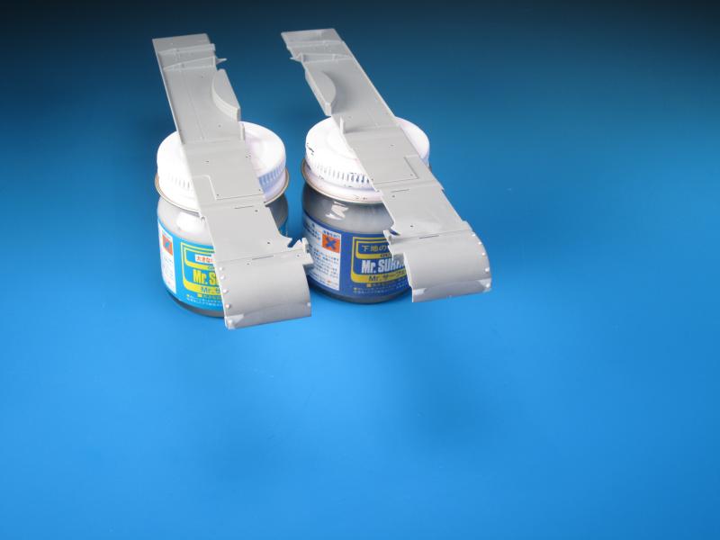
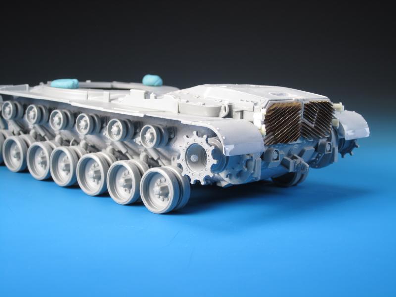
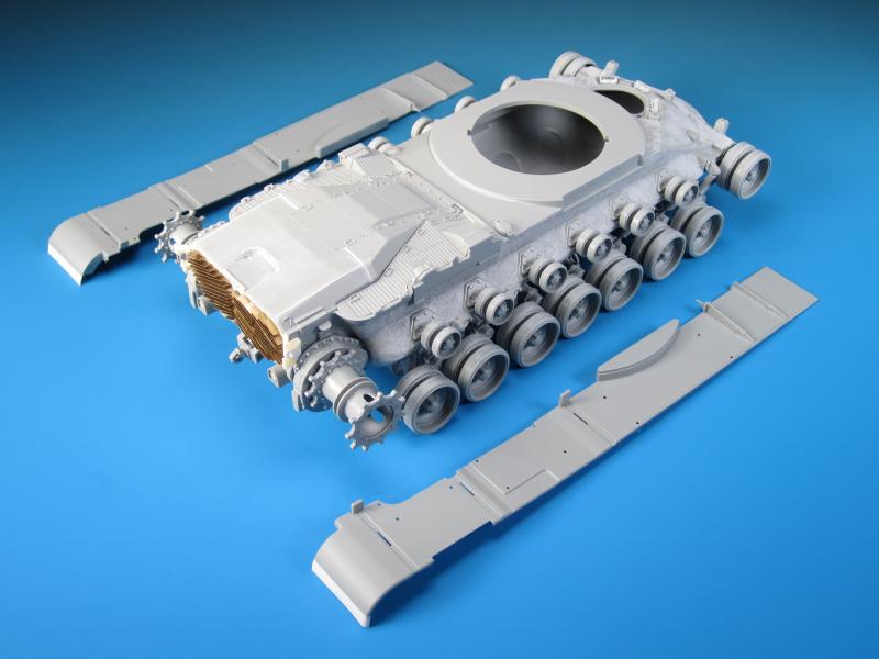
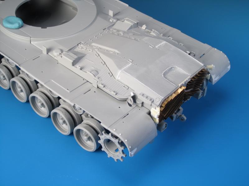
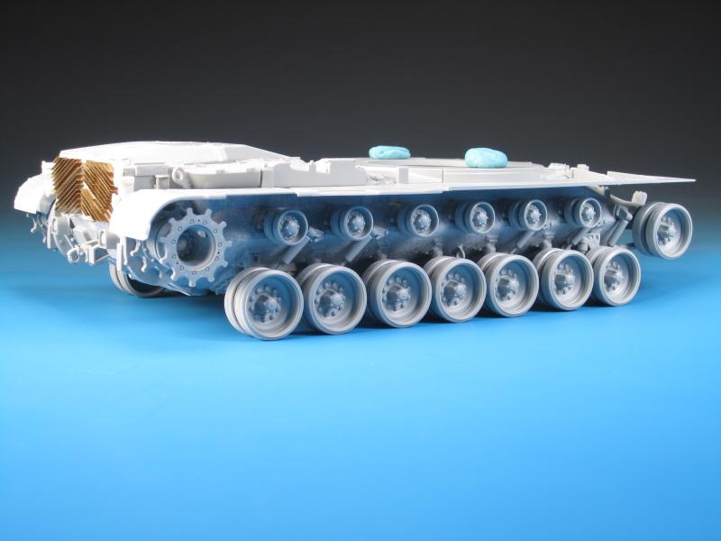
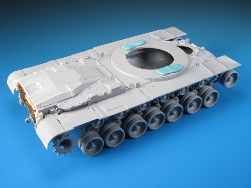
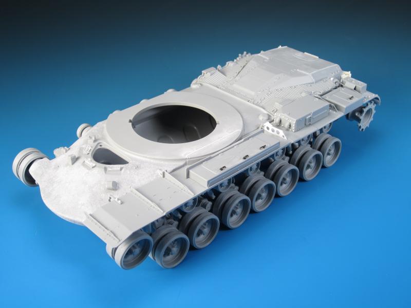
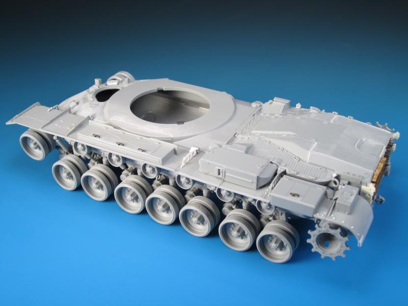
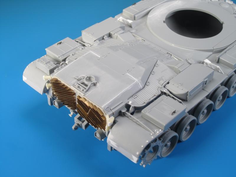
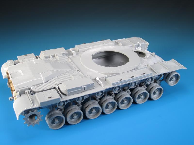
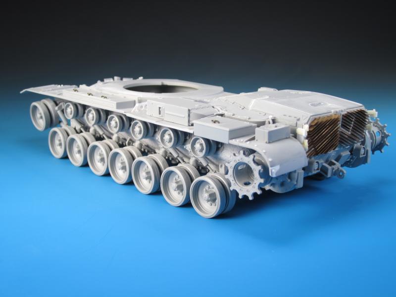
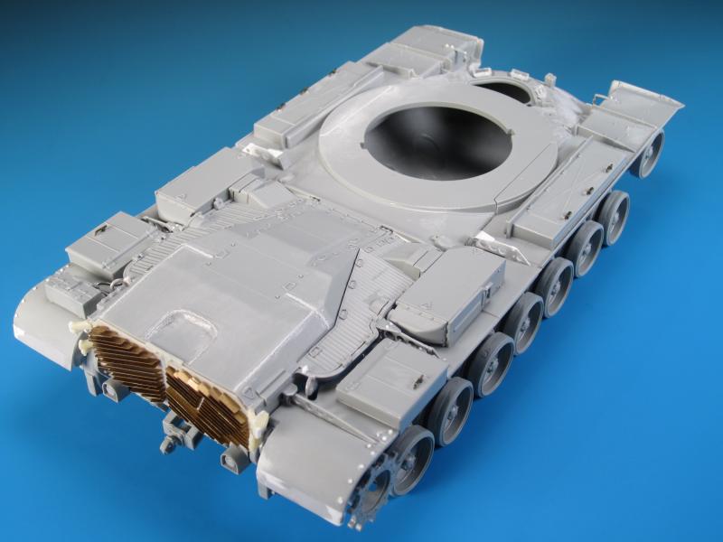
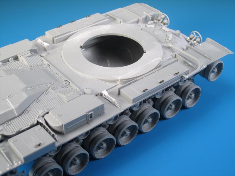
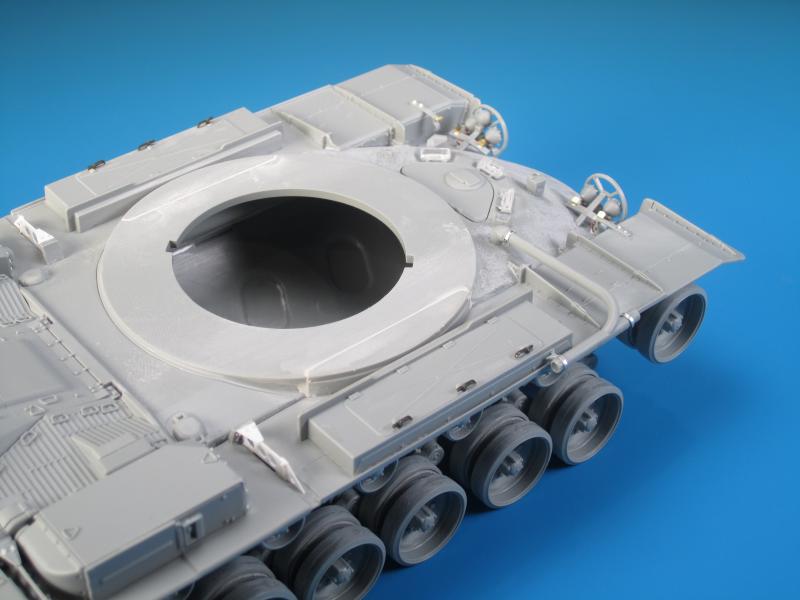
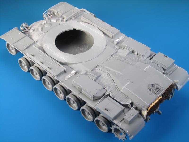
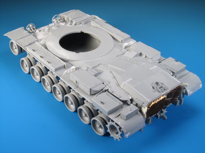
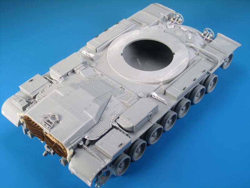
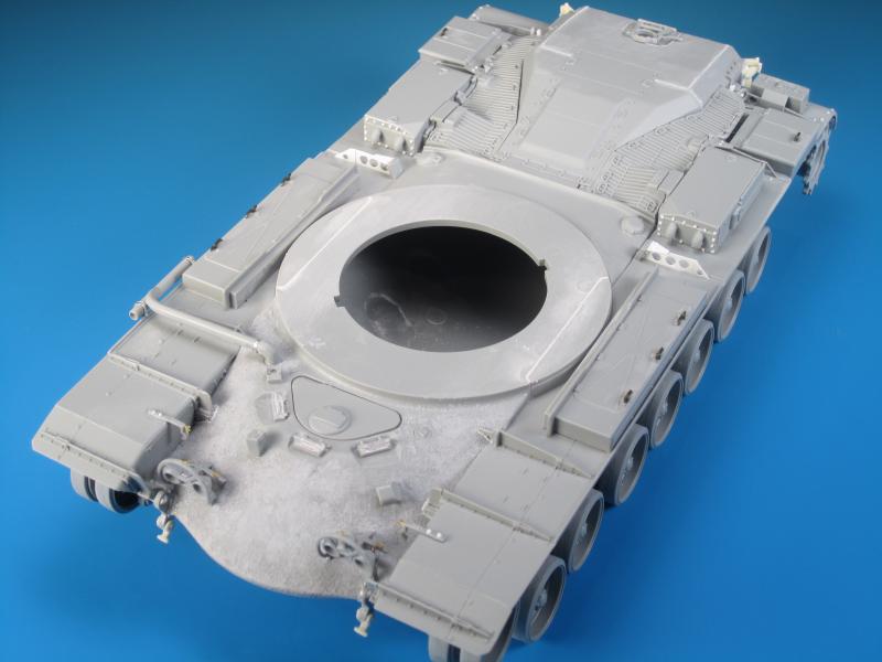
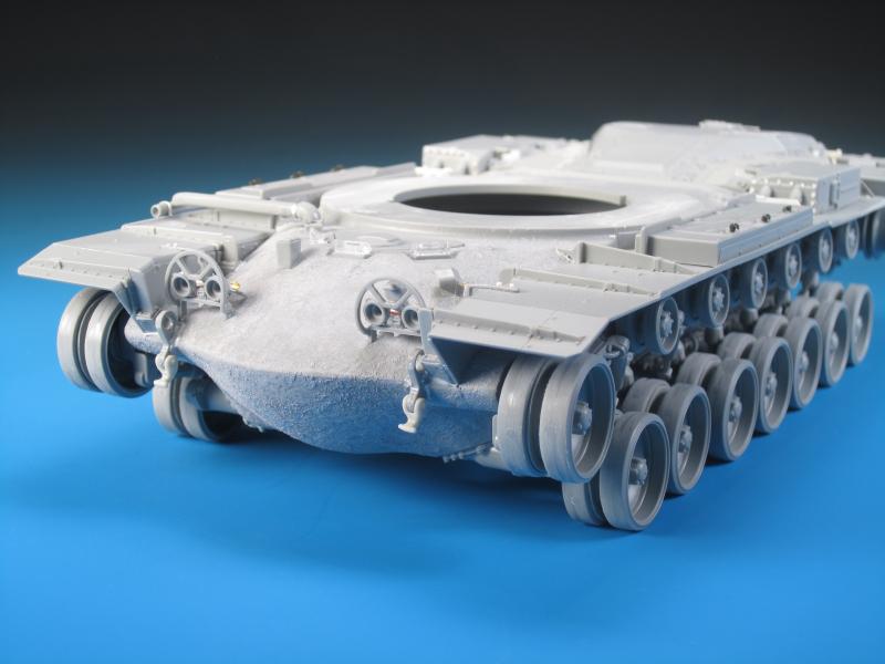
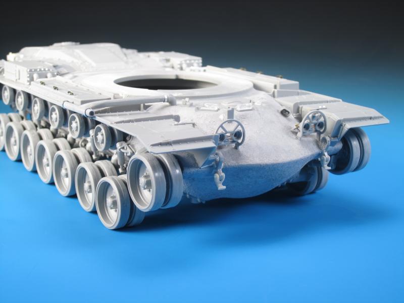
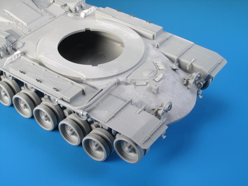
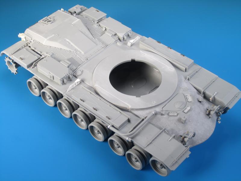
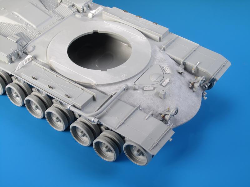
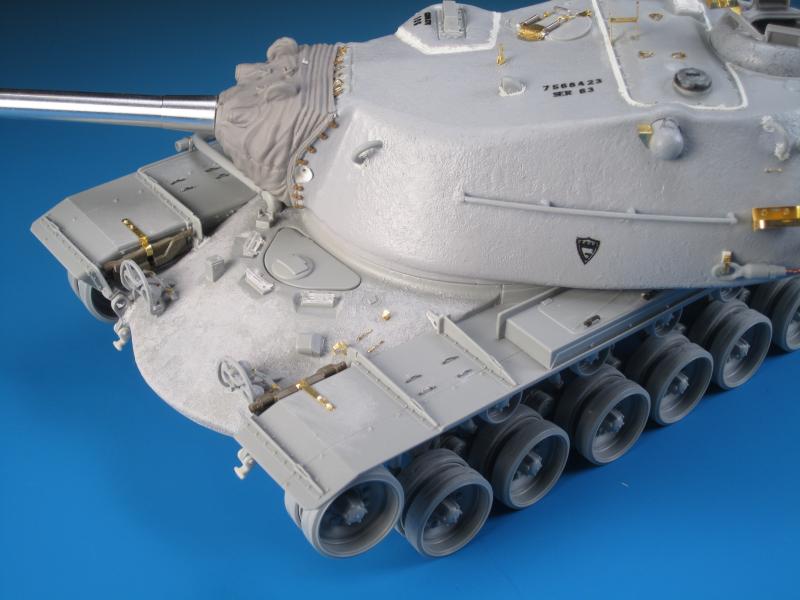
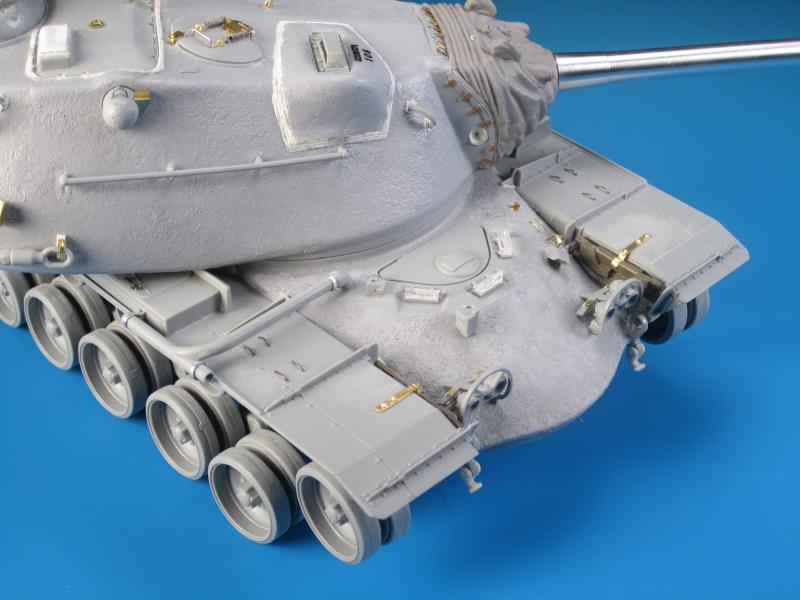
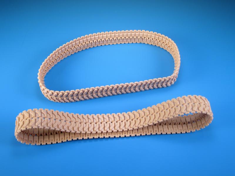
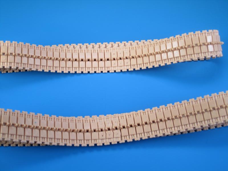
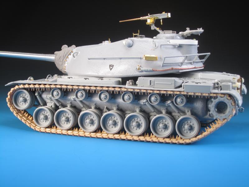
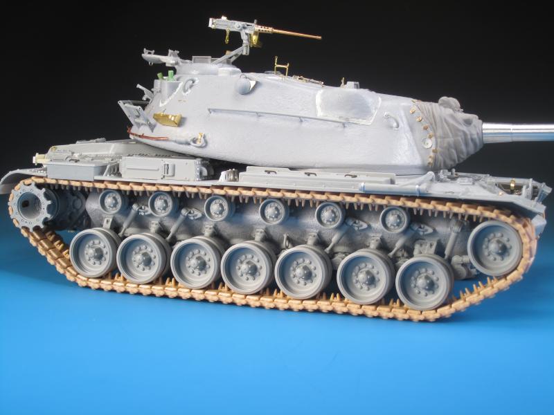
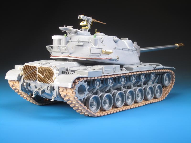
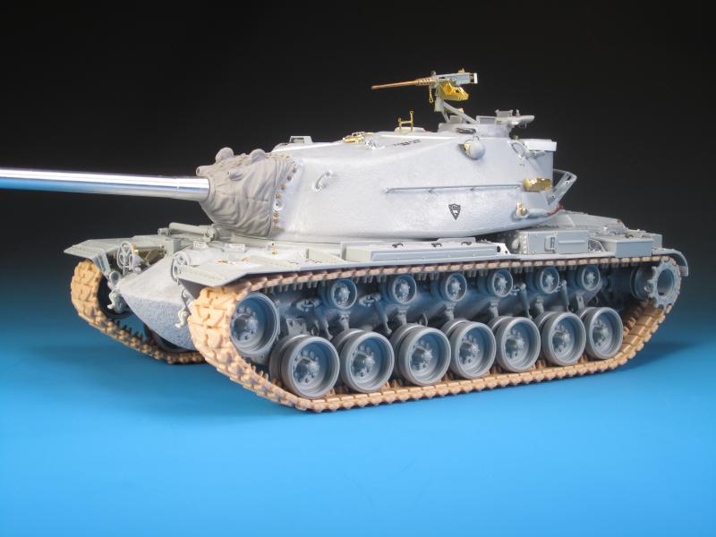
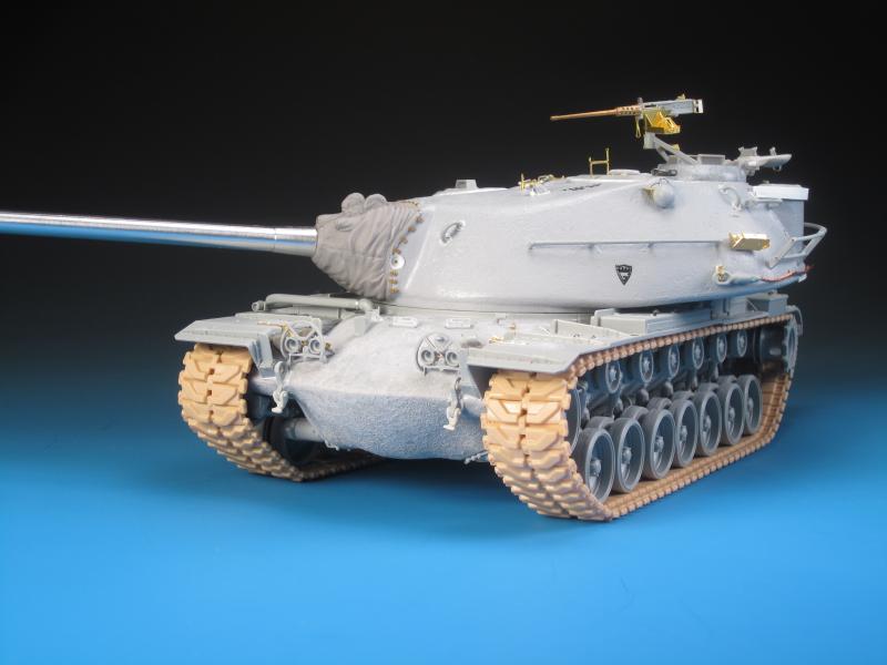
The fenders required a small extension to make them more accurate. For some reason Dragon designed them about 3-4 millimetres too short. I used 0.25 x 4.0 mm Evergreen strip styrene to create the extra length. The edges were curved manually to create a slight wrap. In order to blend the styrene addition to the kit fenders a healthy dose of Mr. Surfacer 500 was applied over the seams. The next step was to sand down the surface and add the missing bolt detail on both fenders, as well as to cut out the recesses for repositioning the rear hull lifting eyes. The lifting eyes needed to be relocated to the proper position on the hull rather than magically attached to the fenders. A small angled addition was added on to each lifting eye to fit it to the hull. In reality, very little can be seen when the fenders are attached. Another small add-on was two small mounts on the lip of engine deck area on the inside of the lifting eyes. These are the attachment points for the supports used on the fording tube when attached to the rear hull. I next tackled the left fender details and attachment. Additional bolt details were added to the fenders as required using a simple punch and die set. In looking continually what I could live with and what needed to be changed, I decided to leave the USMC tank phone the way it is without changing the size. I did add a solder power cable running from the rear of the phone through the hull support and to the hull side behind the air cleaner. I also drilled out the small indicator light on the top of the phone in anticipation of adding a very small red lens. I removed the moulded on handles on the stowage bins and replaced them with styrene handles from the Academy M60A1 RISE kit. I also added multiple bolts to the front of the air cleaner. The kit has all the bolts present on the rear side, but nothing on the front. I noted that on the fender there is visible bolt detail for the most part. The only issue is that the bolts detail seems a bit small. But it is there, and I can live with that. There are three sponson supports that attach to the fenders at intervals. They would act as reinforcements for the fenders. In regards to the kit parts, the rear most support looks overall correct except for missing some bolts, and the flat cover plate should not be there (I left the panel in place). The middle support is overall OK too, but the top cover plate is not the correct shape and is missing bolts. There should also be another hole in the small add-on part at the end of the support. This was easy enough to drill out. The forward most support arm is not correct. It has four large holes and it should only have three large holes and then a small hole on the add-on part. The mounting post should also be angled. I tackled this by simply scratch building a new support from thin styrene. The holes were drilled and the mounting post was simply bent over at an angle. The fit of the fender on the hull is very good. The front fender support overlap on to the glacis plate. I had to reposition the front mount on the glacis plate to properly align it with the support arm. Once in place styrene road weld beads were added as a finishing touch. Overall a straight forward sub-assembly of the build but with the extra details and corrects that I completed it does take time. The right fender assembled without any issues and was given the same treatment of bolt detail and a new sponson support, as was done on the left fender. You can see the slight gap created on the turret ring when attaching the fender. This is easily filled and sanded if you are concerned it will be seen when the turret is attached. As far as accuracy goes, the distance between the sponson supports and the stowage bins and air cleaners seems to be a bit too large. The especial inaccuracy is created on the upper hull area between the turret ring and the engine deck cover. The engine deck cover should be essentially flush behind the turret ring. In essence, the area behind the turret ring is stretched and the area in front of the turret ring is compressed resulting in the turret sitting too far forward. I can accept the discrepancies in the size of the parts as part of the larger build. In looking at reference images it is clear that the gun travel lock is undersized. The detail on the kits parts is acceptable, but that is far overshadowed by the small size. Without completely rebuilding the parts there is no other option. I chose not to correct the travel lock and simply assembled it and mounted it on the back deck. The instructions are very vague as to the placement location of the actual mount on the engine deck. It's too bad about the undersized travel lock as it even more amplifies aspects of the lengthened hull. On the M103A2 the crew heater exhaust was vented out of the hull and along an externally mounted pipe to the right hull side. The kit parts are sufficient, but do have mould seams that need to be removed. Once mounted I added additional foil clamps to enhance the detail. The headlights were added to the hull. Both left and right headlight assemblies are best assembled in stages to ensure proper fit and positioning. The kit provides the basic components for the headlight assemblies but there are a few details lacking. On the hull behind each frame should be an electrical connection on the hull for the headlight wiring. This was easy enough to add with some styrene disks. Each light on both the left and right assembly should have two wires protruding that run to a common harness, which then continues on the connection point. I used very thin copper wire to add the headlight wiring. On the rear of each light assembly is a cross shaped support brace that runs from the assembly to the glacis plate. Missing from these parts are small inverted L-shaped brackets. I added the brackets from the Voyager Model set designed for the M103A1 kit. The kit provides clear plastic lenses for the headlights and IR lights. It will be your choice whether to use them or find a suitable more realistic alternative. Some of the last steps in the completion of the hull build, minus the attachment of the tracks, were the simple addition of tow pintles on the front and rear hull. These are not included in the kit unfortunately, but Legend Production provides four excellent resin T-shaped tow pintles in their M60A1/A3 detail set. I replaced the mould on fender tie-downs with PE versions. I also used parts from the Voyager Model detail set to add pioneer tool rack components. Finally, I ended up removing the Dragon kit parts for the spare track holders. I used a couple of track links and mounted them using the PE spare track holders from Voyager Model set. I found it odd that Dragon included styrene spare track racks but the additional detail of two spare track links was omitted. The Dragon kit provides two single piece DS tracks. I've never used these tracks before and thought them to be unique. They are pliable, bendable, nicely moulded with details, and can be assembled with glue. I have not used OOB tracks in many years. I noted on these tracks a small amount of flash. This was primarily on the inner tracks pads combined with slight sink marks. Assembly of the tracks is no problem with some fine liquid cement of your choice. I used Tamiya Ultra-Thin. Getting the ends of the tracks together with the male and female parts was a bit of a challenge as the ends are fiddly. Once the tracks were assembled and dried they popped on to the suspension without any issues. What I did not like was the unnatural sit of the tracks on the return rollers and around the sprocket. With the DS tracks there is still that "rubbery" tension common to vinyl tracks and they just don't quite sit right. So... off they came and they were replaced by the Bronco Models T97E2 track set. The M103 tracks are not T97 tracks, they are the T107 tracks which are a bit different in dimensions. In 1/35 the T97E2 tracks will do just fine.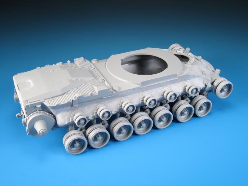
About the Author


Comments


Thanks very much again Fellas! I really appreciate your positive feedback and comments.
What's next? I've got a few Leopards to get back to but as far as Cold War Heavies...a German KPz 70 and a British FV4005 are on the list.
MAR 10, 2016 - 04:01 PM
Which was more work, building the kit or writing that article? Both are a great effort. Nice to see something a little less covered here.
MAR 13, 2016 - 05:52 AM
Building the kit was for sure much more work. I'm glad you like both results!
MAR 13, 2016 - 09:55 AM

Thanks Colin...with any luck I will have it at the Alberta Open Model Contest in Edmonton at the end of May.
MAR 13, 2016 - 11:56 PM

Thanks Bob! Not nearly what you bring to the table with your amazing ships!
MAY 12, 2016 - 05:00 AM
Copyright ©2021 by Jason Bobrowich. Images and/or videos also by copyright holder unless otherwise noted. The views and opinions expressed herein are solely the views and opinions of the authors and/or contributors to this Web site and do not necessarily represent the views and/or opinions of Armorama, KitMaker Network, or Silver Star Enterrpises. All rights reserved. Originally published on: 2016-03-08 14:36:15. Unique Reads: 20561

WEB HOSTING BY


Copyright ©2021 Armorama and Kitmaker Network, a subsidiary of Silver Star Enterprises
All Rights Reserved. Please read our Conditions of Use and Privacy Policy.
All Rights Reserved. Please read our Conditions of Use and Privacy Policy.