

1⁄35M103A2 Heavy Tank
18
Comments
Part 4 - Tempest Turret
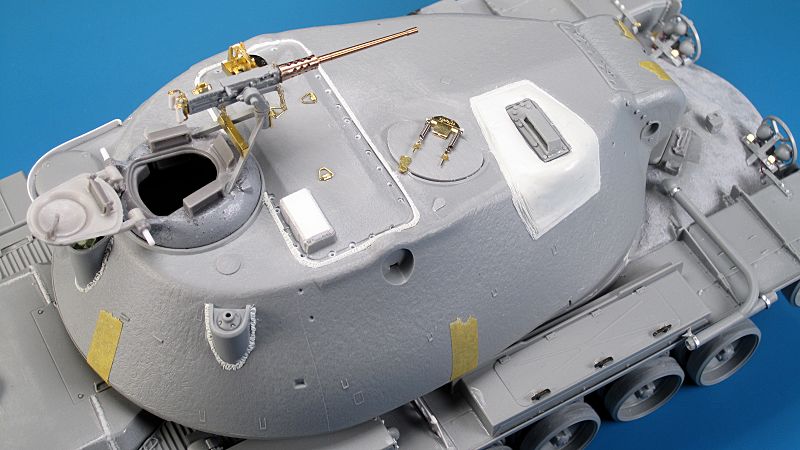
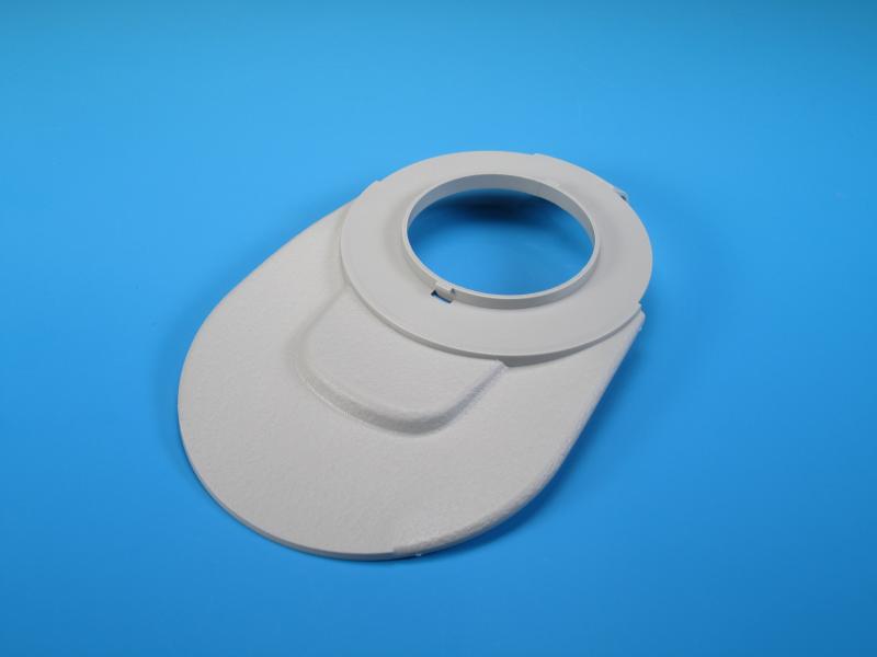
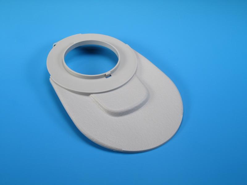
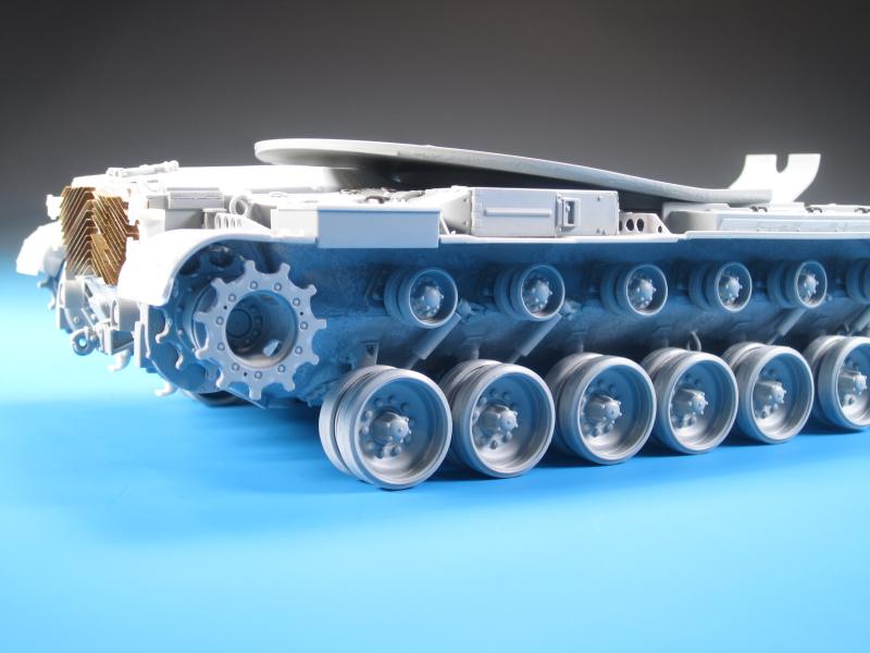
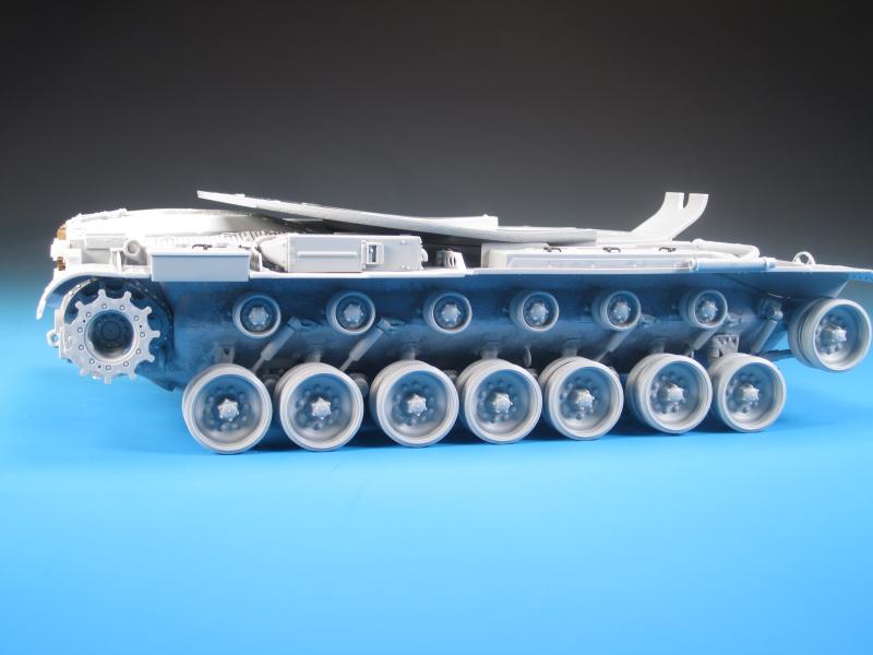
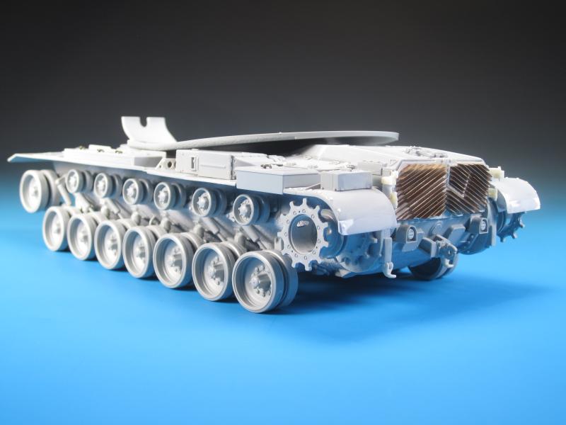
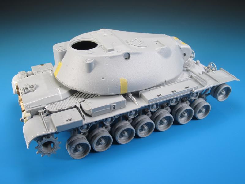
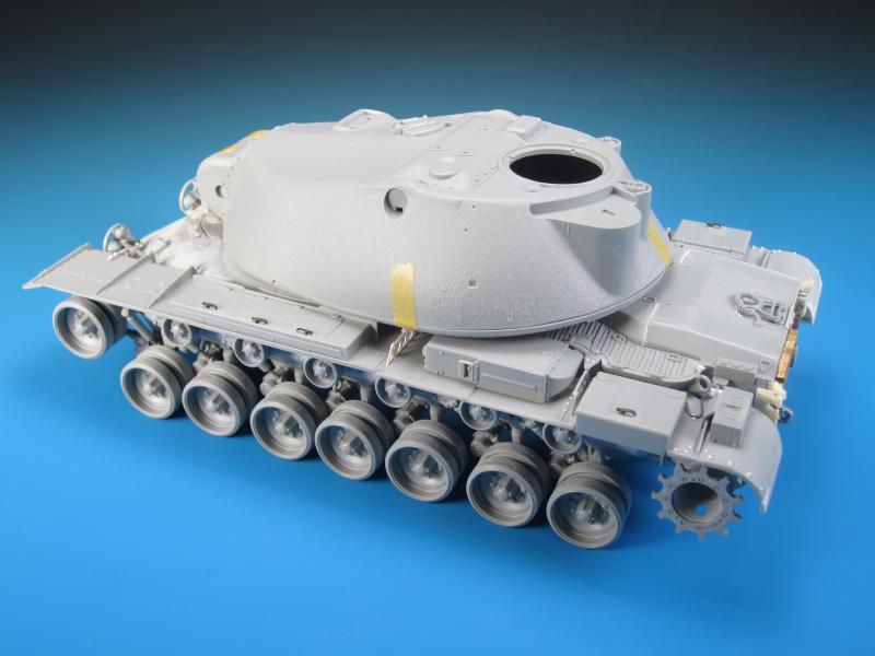
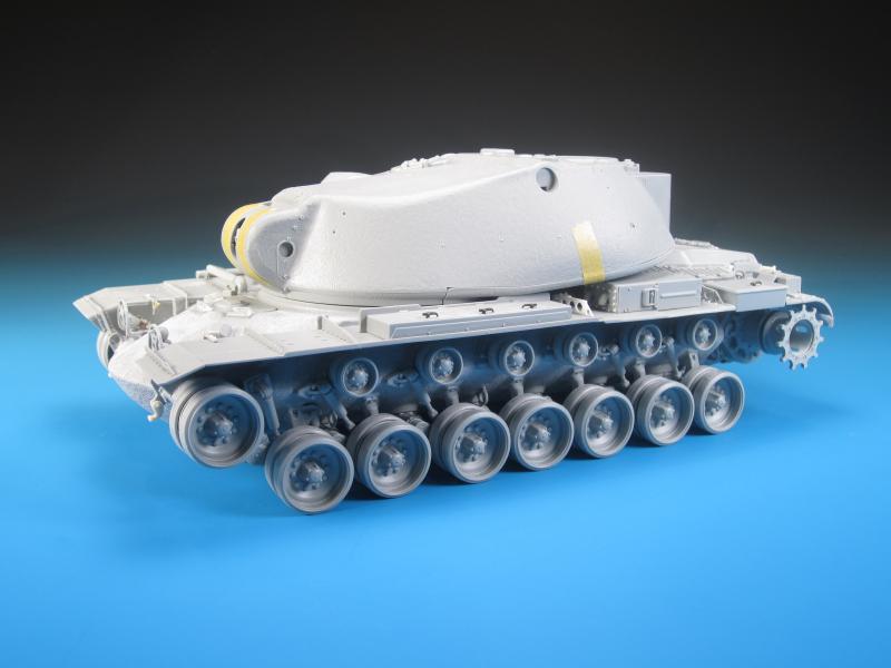
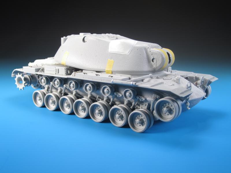
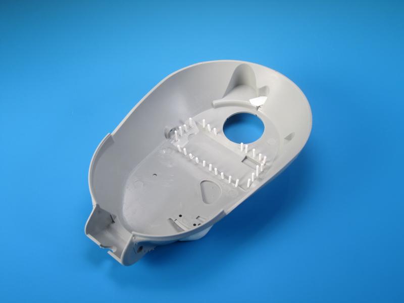
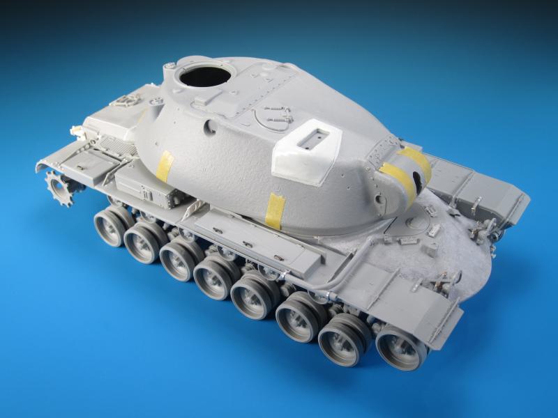
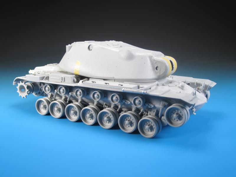
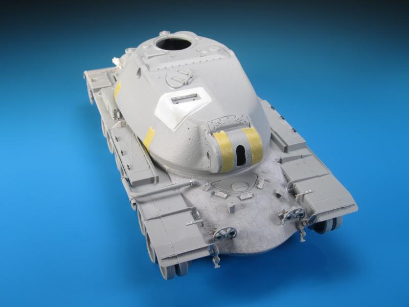
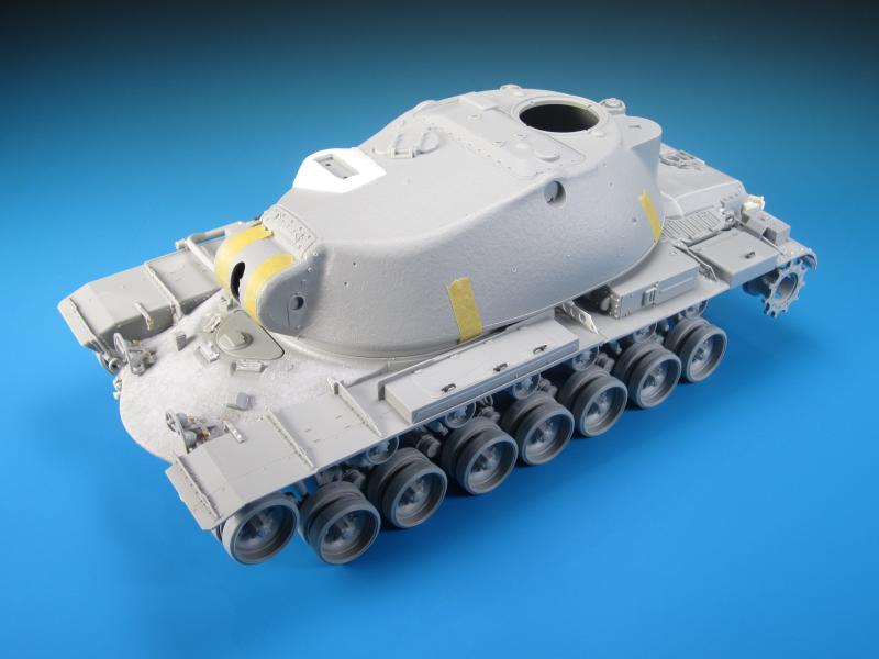
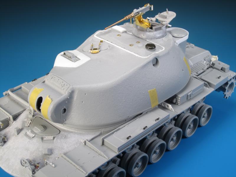
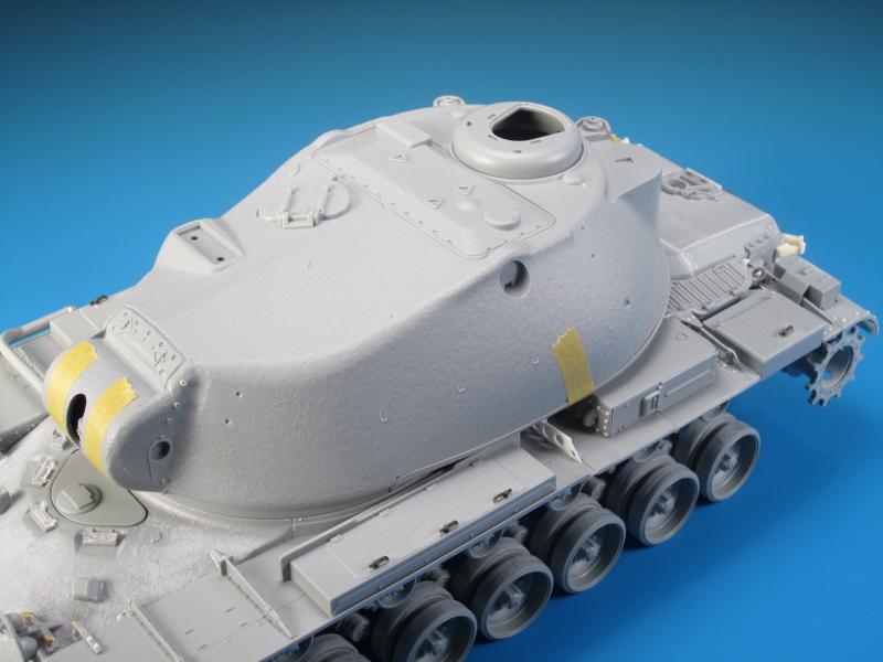
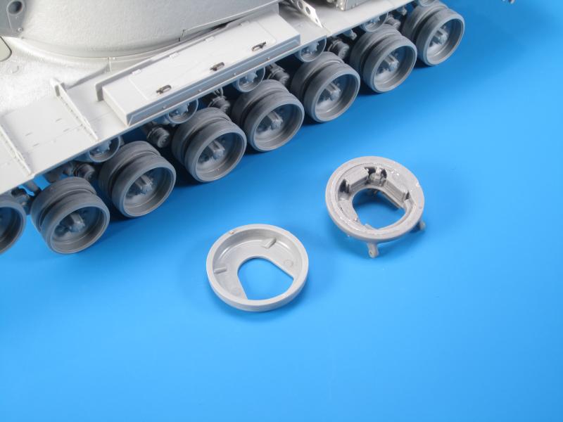
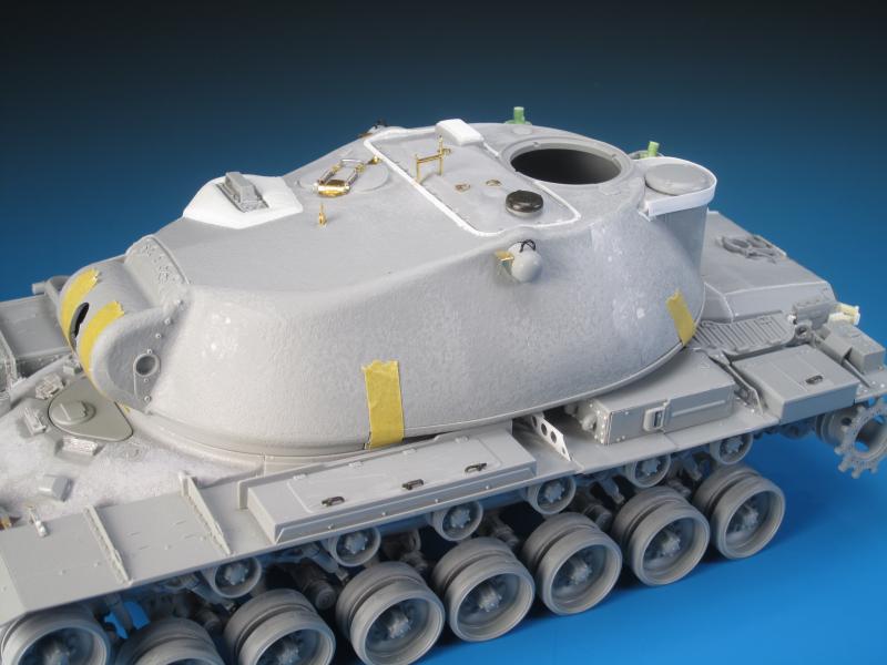
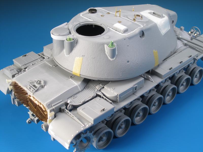
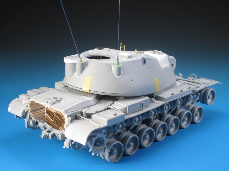
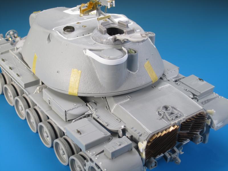
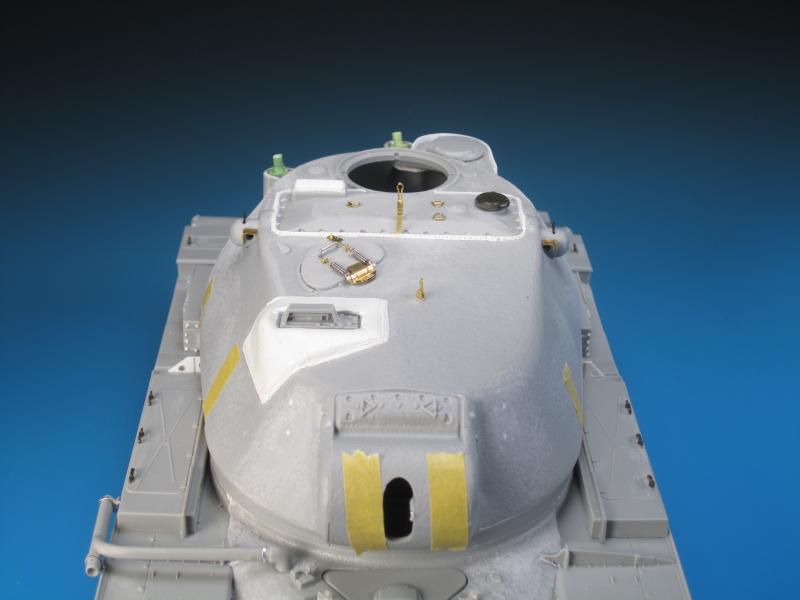
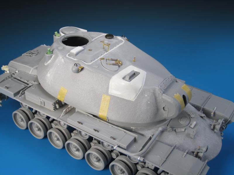
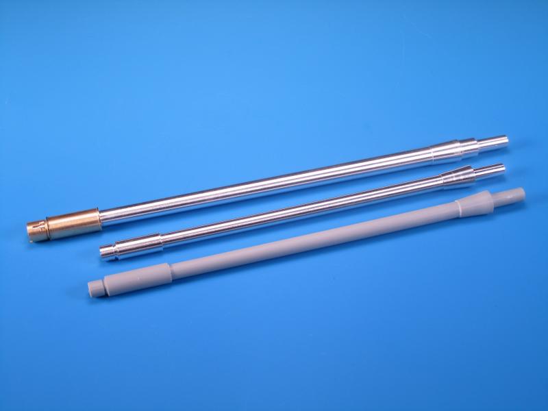
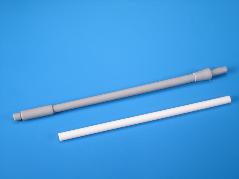
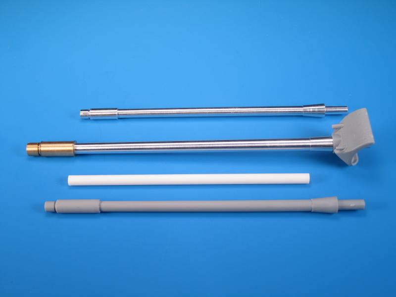
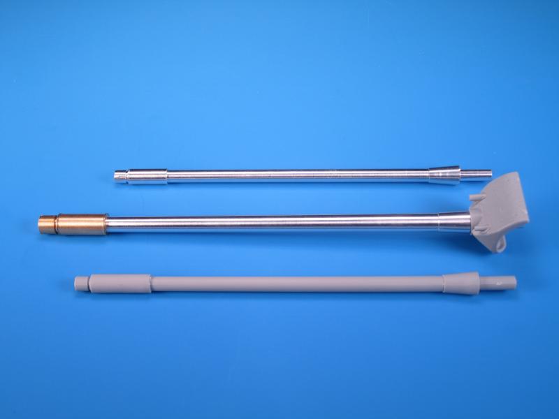
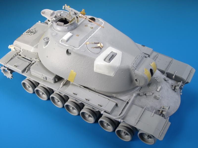
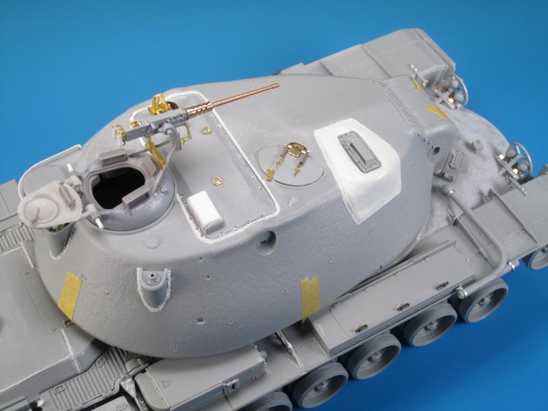
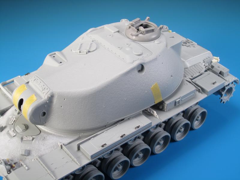
In moving to the turret I wanted to address the detail located on the bottom of the turret first. On the turret bottom there is a visible bulge. On the M103A1 this bulge was used to situate the gunner's position. On the M103A2 the gunner's position was moved forward in the turret and the second coaxial machine gun was eliminated. The complete replacement of the M103A1 engine deck with the new raised style created clearance issues with the redundant bulge. On the M103A2 the bulge was reduced by at least 50% to clear the back deck. The kit provides the turret bottom with what is supposed to represent the full sized bulge. Due to issues with the turret depth and length, the full size bulge actually clears the M103A2 back deck. Without cutting off the bulge, adding a new one with putty, and sanding it to shape there is no option to get this detail accurate. I had strongly considered doing the surgery, but once I test fitted the turret bottom, I realized that with the turret forward you can barely even see the full size bulge and would likely hardly see a reduced bulge. With that being said the bulge will stay as it is in the kit. I taped the upper and lower turret parts together and mounted them on the hull to give an idea of the massive size of the turret. The 120 mm main gun needed a large turret for the recoil system. The size of the turret also greatly increased the amount of armour protection for the crew. This tank was designed to pound the enemy but also take a pounding itself. There is cast texture on both parts which is a positive, as well as an angled top of the turret, which was omitted in the M103A1 kit. There are plain and simple accuracy issues with the turret as well as details missing. As I did with my approach with the hull, I will pick and choose which to address and which to live with. While examining the turret details of an M103A2 it is impossible not to notice the 120 mm main gun. The M58 was capable of firing Armour Piercing, High Explosive, HEAT, and White Phosphorus rounds. It was designed to reach out and touch the enemy whether it was long range or close in bunker busting. The barrel in the Dragon kit is included as a one-piece component. There are mould seams but these are easy enough to remove. There is no visible rifling in the barrel. Not too bad you say? Well, this would be great if the barrel was the correct length. I have read the review and accuracy analysis of the M103A1 kit authored by Pawel Krupowicz in combination with the barrel measurements obtained by Robert Skipper. I decided to take my own measurements and threw into the mix the all metal one-piece barrel made by Voyager Model in their detail set. The measurements of the actual barrel portion of the Dragon barrel and the Voyager barrel are the same. But the muzzle and fume extractor of the Voyager barrel is actually shorter than the kit barrel. This makes the overall length of the Voyager barrel even shorter than the Dragon barrel. Enter stage left the RB Models M58 three-piece metal barrel. Based on measurements made by Robert Skipper of the real barrel and the same type of measurements on the RB Models barrel, the results are essentially the same. This would indicate accuracy in the RB Models barrel. End result...the Dragon barrel is too short. The Voyager barrel is even shorter. The RB Models barrel is just right. Can the Dragon barrel be fixed? Sure, cut the barrel behind the fume extractor and at the angled collar. Use styrene tube the same diameter and cut it to 114 mm long. Glue the parts back together with the styrene tube in the middle and you should now have a barrel very close to the correct length. The plus of this kit bashing is that you can increase the barrel length without much cost or effort. The downside is that styrene tube won't have a slight taper. But, neither does the Dragon Model barrel so you can decide what you can live with. The commander's cupola is very prominent on the already large turret. Using the Chrysler cupola as the commander's station on the M103 series allowed for a remote control .50 Cal HMG on the original M103. As the M103 progressed to the M103A1, the remote system was removed and replaced with a simple pintle mount. The pintle mount was carried over to the M103A2 for the USMC. Given the location and height of the .50 Cal HMG, the commander would have had to have been very exposed in the cupola to have fired it. The Chrysler cupola permitted for an all-round view for the commander via four periscopes. Three of the periscopes are mounted in the cupola base, while the fourth is mounted in the hatch. The hatch is very low profile and is actually quite small compared to hatches present on the M48 and M60 series during the same time period. The kit provides a multi-piece cupola and machine gun mount. The cupola itself is nicely moulded and fits into the turret top like a glove. The hatch is void of any detail on the inside and this does deter from posing it open. The machine gun parts are for the most part from the Dragon M3 Halftrack kit. The cradle parts are thin and fit the .50 Cal body well. The .50 Cal is comprised of a receiver with barrel, spade grips, barrel changing handle, and a feed cover. There are also three pieces used to create the feed tray and ammunition box. I found these last parts very basic and the assembly process creates unrealistic seams. The .50 Cal HMG needs a bit of cleaning up with the removal of the Traverse and Elevation (T&E) gear that is present on the Halftrack parts. The cupola surfaces are very smooth, and in fact the surface should be a bit rougher to replicate the heavy cast surface. The kit cupola can be further detailed to your liking using a few options. The .50 Cal can be detailed with aftermarket parts or simply replaced with a better detailed version. The cupola surfaces can be roughed up with Mr. Surfacer or a similar product application. Overall this would improve the detail in the kit parts. If you want to pose the hatch open you will need to look at additional detailing such as a more detailed hatch lock on the rear of the cupola, an internal hatch handle/lock, the inside hatch components of the fourth periscope, and potentially details visible inside the cupola. I decided to pose the hatch open and therefore went for the option of using the Slingshot Models M48 Patton Early Type Commander's Cupola. This little set has excellent details inside and out and perfect for detailing the M103A2 kit. I removed the remote firing mechanism from the resin cupola and assembled it using the Slingshot Models' parts in combination with the applicable Dragon parts. Added on for further detailing was the Voyager Models M103A1 detailing parts which provides a replacement barrel, cooling jacket, pintle chains, feed tray, front and rear sights, and an ammunition box. The Slingshot Models' cupola contains excellent external and internal details. Inside cupola and hatch detail, wire for the hatch handle, and a seamless fit to the Dragon Model turret are all positives with this replacement part. The only other detail I added was a thin application of Mr. Surfacer 1000 to provide enhanced cast texture. As the M103 progressed to the M103A1, the gunner's position was repositioned forward in the turret. Concurrently, the gunner's sight periscope was placed forward on the turret roof resulting in the visible welded bulge on the right side of the turret. Dragon has included the bulge on the turret top part but it is undersized and visibly lacking the weld seams. In looking at options, I could leave it alone or add the bulge. I chose the latter and used Tamiya Smooth Surface two-part epoxy putty. I find this product easy to mix, easy to add to a surface, and it easily has a long enough setting time to make large and fine adjustments and add weld details. While the epoxy putty was still flowing I decided to add other details to the turret. The two antenna mounts on the turret rear have very fine weld detail moulded on but it needed to be enhanced. On the turret top in front of the commander's cupola is a larger rectangular hatch. The removal of this hatch would expose the majority of the main gun fire control systems. Further detail can be added to this area by way of enhancing the rim around the hatch. Dragon depicted the edge as flat with a recessed area around the multiple bolt locations. Missing are all of the recessed bolts, and the edge should in fact be raised with a weld bead. I used .010 x .030" strip styrene to create a raised lip around the hatch and then used a fine bead of epoxy putty around the lip to create the weld bead. I tackled the recessed bolts (all 22 of them) as the turret progressed. The Voyager Models set provides some really good details for the turret, including replacement details for the loader's hatch, and lifting latches for the rectangular hatch. As a preparatory move I sanded off the three triangular lifting latches on the rectangular hatch and all of the loader's hatch details. On the left and right of the cupola ring there are two raised and rounded fixtures. For the M103A2 these are sanded down significantly from their original state. This was an easy adjustment with a couple of minutes of sanding. Continuing with the turret details, I next drilled out all of the nonexistent bolt holes around the fire control access hatch. Dragon did attempt to replicate the bolt locations but fell short with incorrect locations, lack of detail, and they even left some out. My approach with this was to simulate the countersunk bolts and not do a complete overhaul on the hatch. I first drilled out all the existing locations and added the four missing from the rear of the unused gunner's secondary sight housing. Next, I enlarged the holes slightly on the underside of the turret roof and carefully pushed up small styrene rods into the holes so they simulated bolts. With small dabs of Tamiya extra thin liquid cement they were set aside to dry. Once dry I used a very small pin vise drill bit to drill out a countersunk hole in the top of each "bolt". Once this was complete the look of multiple countersunk bolts was around the perimeter of the hatch much more realistically than the Dragon kit, but not totally accurate due to the Dragon parts. The blade vane sight mounted on the hatch and turret top was also added. While finishing off the hatch I added a small rectangle of styrene to the top of the unused gunner's sight housing and added weld beads using styrene. The hatch handles had been previously sanded off and they were replaced with brass versions from the Voyager M103A1 set. The loader's hatch was sanded down a bit more as I thought it sat too raised from the turret and I added the details provided in the Voyager set. I still have to add a bent wire hatch handle and the hatch lock positioned toward the center of the turret. On the turret rear I drilled out the left antenna mount. On the M103 series the left antenna mount is set at an angle. My guess is at about a 20 degree angle. I suspect this was to provide clearance for the open commander's hatch. My plan was to replace the antenna mounts with newer more modern versions with springs. I have seen images of M103A2s with more modern antennas and mounts but I am not sure if they are just a restoration feature or if the antennas were updated while in service. With the M103A2 in service into the early 1970s I could see it being possible for more modern antenna mounts to have been used. I removed the moulded on lip of the main turret ventilator mount. It was too thick compared to the real thing. After sanding it off I replaced it with a cut styrene strip which was formed around the contours. The Dragon kit includes a loader's hatch lock, but it is chunky and not very detailed. I simply swapped it for the PE version provided in the Voyager M103A1 detail set. The Dragon kit also provides a plastic Blade Vane sight for the turret top. Once again, it is chunky and replaced with the excellent parts from the Voyager set. I thought about what I wanted to do with the antenna mounts. The left one for sure needed surgery to cant it at an angle. In the end I found a picture of an M103A2 in the Ampersand M103 Heavy Tank book showing an M103A2 with two more modern antenna mounts, which included the antenna mounting unit with the spring. These are commonly seen on a multitude of modern vehicles. I drilled out both antenna pots and replaced the mounts. On the right mount I simply replaced the kit version with a resin version from a Maple Leaf Models set. Prior to attaching the mount I cut off the resin spring. The left mount required more work and I needed to replicate the canted angle of the antenna mount mentioned previously. Again, using a Maple Leaf Models antenna mount I attached it to a piece of styrene rod I had cut to shape and sanded to an angle. The actual antenna when mounted angles toward the center of the engine deck and not straight back. I next drilled pilot holes into both resin mounts. I cut thin steel wire for the antennas and fed it into the pilot holes. Next I used the excellent metal springs provided in the Voyager set and simply slid them over the wire antennas. The next step was to use the small brass antenna bases provided in the Voyager set. The problem with these parts is that Voyager did not mill them hollow to accept the antenna. There are small indents on either end but I wanted to reinforce the parts. Using the same drill bit I used for the pilot holes I clamped each brass part and drilled them from top to bottom creating a hollow core. Voila! I simply slid the brass antenna bases on to the antennas to mate up with the springs. In my opinion the springs are a touch under scale but the look of both completed antennas is very nice. I temporarily mounted the antennas and during final assembly they will be fixed with CA glue to be at the proper angles. On the turret, the range finder blisters are thankfully included as separate parts to allow for additional detailing. The blisters might be a bit undersized but they are totally suitable for the build. I added small lifting loops on top of each blister with thin metal wire. Next I used PE parts from the Voyager M103A1 detail set to replace the kit moulded on optics covers. They are much thinner than the kit version and add a better scaled look. Finally I drilled out apertures for optics on each blister. Dragon simply did not include any details for the optics. In reality the apertures should be oval.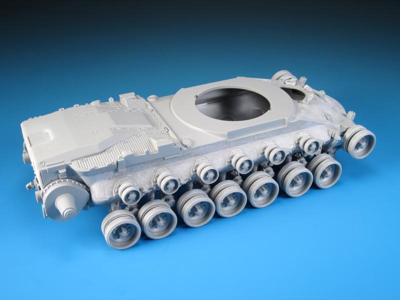


About the Author


Comments


Thanks very much again Fellas! I really appreciate your positive feedback and comments.
What's next? I've got a few Leopards to get back to but as far as Cold War Heavies...a German KPz 70 and a British FV4005 are on the list.
MAR 10, 2016 - 04:01 PM
Which was more work, building the kit or writing that article? Both are a great effort. Nice to see something a little less covered here.
MAR 13, 2016 - 05:52 AM
Building the kit was for sure much more work. I'm glad you like both results!
MAR 13, 2016 - 09:55 AM
Thanks Colin...with any luck I will have it at the Alberta Open Model Contest in Edmonton at the end of May.
MAR 13, 2016 - 11:56 PM

Thanks Bob! Not nearly what you bring to the table with your amazing ships!
MAY 12, 2016 - 05:00 AM
Copyright ©2021 by Jason Bobrowich. Images and/or videos also by copyright holder unless otherwise noted. The views and opinions expressed herein are solely the views and opinions of the authors and/or contributors to this Web site and do not necessarily represent the views and/or opinions of Armorama, KitMaker Network, or Silver Star Enterrpises. All rights reserved. Originally published on: 2016-03-08 14:36:15. Unique Reads: 20561

WEB HOSTING BY


Copyright ©2021 Armorama and Kitmaker Network, a subsidiary of Silver Star Enterprises
All Rights Reserved. Please read our Conditions of Use and Privacy Policy.
All Rights Reserved. Please read our Conditions of Use and Privacy Policy.